TAU STERIL FAST B User manual

TAU STERIL N° 11 - Rev. 3 03/02/20
User Manual Page 1 FAST B
User Manual
Fast B
0426
DIRECTIVE 93/42 CEE E S.M.I.
MEDICAL DEVICES
Via Gorizia 6/a – 22073 Fino Mornasco – COMO –IT
Phone 0039 31 927226 Fax 0039 31 880734
E-mail: [email protected] Web: www.tausteril.com

TAU STERIL N° 11 - Rev. 3 03/02/20
User Manual Page 2 FAST B
INDEX
Number Title Page
1Warnings and Safety 3
1.1 Relevant standards 4
1.2 Intended use 4
1.3 Recommendations 4
1.4 Skills required of the personnel 4
1.5 Use and keeping of the manual 5
1.6 The manufacturer’s responsibilities 5
1.7 Secondary risks 5
1.8 Safety Devices 6
1.9 Personal Protection Devices (PPD) 7
2Description of the Machine 7
2.1 Items on the front and rear of the autoclave 7
3Installation and preparation for commissioning of the autoclave 8
3.1 Description of demineralised water tanks 9
3.2 First filling with demineralised water 9
4Operation 10
4.1 Description of touch-screen icons 10
4.2 Main menu 12
4.3 Description of the main menu 12
4.3.1 Language 12
4.3.2 Print data 12
4.3.3 Date/time 13
4.3.4 Formats 13
4.3.5 Internal printer 14
4.3.6 Screen 14
4.3.7 Maintenance 15
4.3.8 Service 15
4.4 Cycle menu 16
4.5 Opening/closing door and stopping sterilisation cycle 17
4.6 Delayed start of cycle 18
4.7 Starting an operating cycle 19
4.7.1 Anti-condensation ventilation phase 21
4.7.2 Info. button 21
4.8 Alarm messages and signals 22
4.9 Printer 24
5Maintenance and cleaning 25
6Decommissioning and scrapping of the appliance 26
7Electrical circuit diagram 27
8Hydraulic diagram 28
9Type plate and explanation of symbols 29
App. 1 Technical data 30
App. 2 Preparation of instruments for sterilization 31
App. 3 Looking after sterilised instruments 32
App. 4 Description of the Bowie & Dick Test 33
App. 5 Description of the Helix test 34
App. 6 Description of the Vacuum Test 35
App. 7 Validation of cycles 36
App. 8 Water quality 37
App. 9 Accessories supplied and spare parts for maintenance 38

TAU STERIL N° 11 - Rev. 3 03/02/20
User Manual Page 3 FAST B
Before using this device, read the following safety information carefully.
1. Warnings and Safety
Remark: this manual provides all the information required to ensure:
correct installation and commissioning
optimum use of the device
continuity of operation
effective periodic maintenance
Failure to comply with the instructions in this user manual can lead to accidents or damage the appliance.
Before using the device, the operator must perfectly understand the meaning of all controls and their operation.
The operator must be acquainted with and know how to apply the safety standards for the use of the appliance.
The operator must know and correctly interpret all the indications contained in this manual and those present on the
device.
The operator must not carry out any operations on his own initiative or any operations not within his competence.
The responsible authority is to be charged with the operator's professional training and development.
In the event of malfunctions or a potentially dangerous situation, the operator MUST immediately notify the responsi-
ble authority of the same.
It is absolutely forbidden to remove or disable the safety devices.
Ensure that the device is supplied with the correct voltage.
Ensure that the installation is earthed in compliance with the standards applicable in the country of installation.
Never dismantle the device. Always contact the competent technical assistance service first.
The high internal voltages are dangerous.
If you cannot turn off the supply, use the main circuit breaker and, if this is distant from or invisible to the person
carrying out the maintenance, hang the notice “Work in progress” on the circuit breaker after setting it to “OFF”.
Keep the area around the appliance clean and dry.
Do not use solvents on the label.
Do not remove the label from the machine. If need be, request new labels.
Clean the device with a damp cloth, after ensuring that the supply cable is unplugged (before using it again, dry
carefully).
Do not pour water or other liquids that might cause short-circuits or corrosion into the device.
Never tough the device with wet hands or when there is liquid present on it; always exercise all the usual precau-
tions for dealing with electrical appliances.
The device is not designed for use in the presence of explosive gases or vapours.
Do not subject the device to excessive mechanical stress such as impact or strong vibrations.
Do no stand over or in front of the door when opening it, there is a risk of being scalded by the escaping steam (see
section 1.7 “Secondary risks”).
In the event of absence of sterilisation, the discharge tank water may contain contaminated residues; so it is recom-
mended to use of latex protective gloves when carrying out emptying operations (see section 3.2 and section 1.7
“Secondary risks”).
Before moving/transporting the device, empty the two water tanks.
Use the special drainage pipe supplied (Appendix 9) and follow the drainage instructions (see section 3.2, page 9).
• WARNING: There shall be no change in this unit.
- In case of malfunction, contact the manufacturer.
- For any repairs, make the sterilizer manufacturer in its original packaging.

TAU STERIL N° 11 - Rev. 3 03/02/20
User Manual Page 4 FAST B
1.1 Relevant standard
Tau Fast B is a class II b medical device in accordance with rule 15 of annex IX to Council Directive 93/42 EEC. It is
further compliant with the national standards derived form the following harmonised standards:
EN 13060 , EN 61010-1, EN 61010-2-040, IEC 62304, EN 60601-1-6, IEC 62366, EN 61326-1, EN ISO 14971
The autoclave Fast B complies with RoHS 2011/65 / EU of the European Parliament and of the Council of 8 June 2011
on the restriction of the use of certain hazardous substances in electrical and electronic equipment.
1.2 Intended use
This device, known as an “autoclave steriliser”, is used to sterilise the instruments placed on the trays supplied, using
specific sterilisation processes with steam from demineralised or distilled water, permitting the treatment of compact,
solid objects, compact, porous materials and hollow bodies of type A and B, not packaged or in single or double pack-
aging.
1.3 Recommendations
The user is responsible for the installation, operation and maintenance of the steriliser in accordance with the in-
structions defined in the user manual.
The autoclave has not been designed or tested for the sterilisation of liquids.
At the end of the sterilisation cycle, the trays and their load are still very hot. Use the specific tongs to pull the
trays out of the sterilisation chamber (see Appendix 9).
Comply with the maximum load as fixed, checked and validated by Tau Steril for each type of material to be steri-
lised (table, page 16), in order to ensure normal operation and effective sterilisation.
Do not remove the registration plate or any other labels from the device.
Do not pour water or other liquids onto the device, this could cause a short circuit.
Before carrying out any service or maintenance operation on the appliance, disconnect the plug from the socket.
Any technical work must be carried out only by assistance centres approved by Tau Steril and using only original
spare parts.
Operations to be carried out before any maintenance and/or return to factory of the steriliser:
- Empty the sterilisation tanks (section 3.2, page 9)
- Allow the sterilisation chamber to cool down
- Only use and always keep the original packaging.
Note, failure to comply with the instructions in this manual can:
make it dangerous to use the appliance
present risks for the operator and to the patient
1.4 Personnel requirements
The personnel assigned to the use and maintenance of the device must meet the following requirements:
- General culture enough to understand the contents of this manual;
- Knowledge of the device and the place where it is installed;
- Knowledge of hygiene, and accident prevention techniques;
- Must be aware of the technical methods, procedures and risks regarding the sterilization process.
OPERATOR is the person who physically uses the device for its intended purpose.
THE PROPER AUTHORITY is the person or group, responsible for the use, maintenance equipment and for operator trai-
ning.
The responsible authority is legally responsible with regard to the obligations concerning the installation, operation and
use of the device.
CAUTION !! TAU STERIL accepts no responsibility for training staff is not properly performed.
"For the date of validity of the aforementioned standards, refer to the Technical File to be requested from the manu-
facturer".

TAU STERIL N° 11 - Rev. 3 03/02/20
User Manual Page 5 FAST B
1.5 Use and keeping of the manual
The present manual is an integral part of the product and must be kept near the device to be easily and speedily con-
sulted. The purpose of the present manual is to give instructions for:
1. the correct installation of the device;
2. the safe and efficient operation of the device;
3. the continued and compliant maintenance of the device.
The device must be used in accordance with the procedures contained in this manual and never for any purpose other
than provided herein. It is further supposed that the directives with regard to the safety of personnel in force in the des-
tination country of the appliance are known and applied at the place of use of the device.
This manual must be kept in a safe place, easily accessible for the personnel; it must also be handled with care.
1.6 The manufacturer’s responsibilities
The device is constructed in accordance with European regulations.
It should be noted that the use of the appliance is limited to the functions for which it was designed and made.
If the autoclave is improperly used, any resulting damage will be the responsibility of the user.
The product is guaranteed for 12 months from the date of purchase.
1.7 Secondary risks
During the normal operating cycle of the appliance, the operator is exposed to certain risks that cannot be totally elimi-
nated, given the very nature of the machine.
1. Danger of burns (scalds).
When the autoclave has completed its sterilisation cycle and the operator opens the door to remove the sterilised instru-
ments, their temperature will be between 70° C and 85° C: beware of the risk of burns, allow to cool for at least two
minutes (door open) before removing from the sterilisation chamber.
Again, at the end of the sterilisation cycle, we indicate the other temperatures in order prevent any burns to the opera-
tor:
Inner part of chamber and door = temperature between 70 °C and 85 °C (Fig. 1)
Outer part of casing = 40 °C
To remove the sterilised instruments from the chamber, use the specific handle supplied (App. 9, page 37). When open-
ing the door, do not stand over or in front of it, there is a risk of scalding by escaping steam (F.1).
2. Danger of accident to the hands.
• When in operation, the cooling fan of the appliance runs continuously. Do not remove the protective outer casing
without switching off the supply. In the event of anomalies, always contact technical assistance.
Fig. 1: Note the arrow s, they indicate
the hot parts of the machine
vvvvvv

TAU STERIL N° 11 - Rev. 3 03/02/20
User Manual Page 6 FAST B
1.8 Safety Devices
Electrical safety
Thermal protection
Mechanical protection
Thermal protection accessories
Description Effect
The vacuum pump and the small water pumps have dual
protection: software and electronic protection components.
The supply to the components is shut off (alarm indication)
to permit the intervention of technical assistance.
Protection fuses (delay) to protect the device from any
short-circuit in the appliance.
General shut-off of the electrical power supply.
Protection of the electronics card against any short-circuit:
the transformer and the whole low-voltage electric circuit
are equipped with automatic protection.
Shut-off of one or more low-voltage circuits.
Description Effect
Resettable safety thermostat to protect the sterilisation
chamber heating element.
Shut-off of supply to the sterilisation chamber heating ele-
ment.
Resettable safety thermostat to protect the steam genera-
tor.
Shut-off of supply to the steam generator heating element.
Thermal protection of the appliance to prevent overheating
(before during and after the start of the sterilisation cycle).
Warning message; use of the machine is prevented in or-
der to protect both the operator and the device.
Description Effect
Safety micro-switch on the door (authorisation): authoris-
es the motor to close the door. Message with signal .
(see section 4.8)
Message and signal authorising the start of the motor for
closing the door.
Safety micro-switch on the door (closure): ensures the
door is correctly closed. Message with signal .
(see section 4.8)
Message and signal if door not correctly closed.
Safety micro-switch on the door (opening): ensures the
door is correctly opened. Message with signal.
(see section 4.8)
Message and signal if door not correctly opened.
Safety pressostat to prevent any accidental opening of the
door (during operating phase): locks the door.
Prevents the motor from starting during operation of the
autoclave.
Description Effect
Handle for withdrawal of trays in order not to touch the
hot parts inside the machine (Appendix 9)
Avoids any burns during the machine loading and un-
loading phases.
TAU STERIL N° 11 - Rev. 3 03/02/20
User Manual Page 7 FAST B
Control devices
1.9 Personal Protection Devices (PPD)
- Latex protective gloves
2Description of the Machine
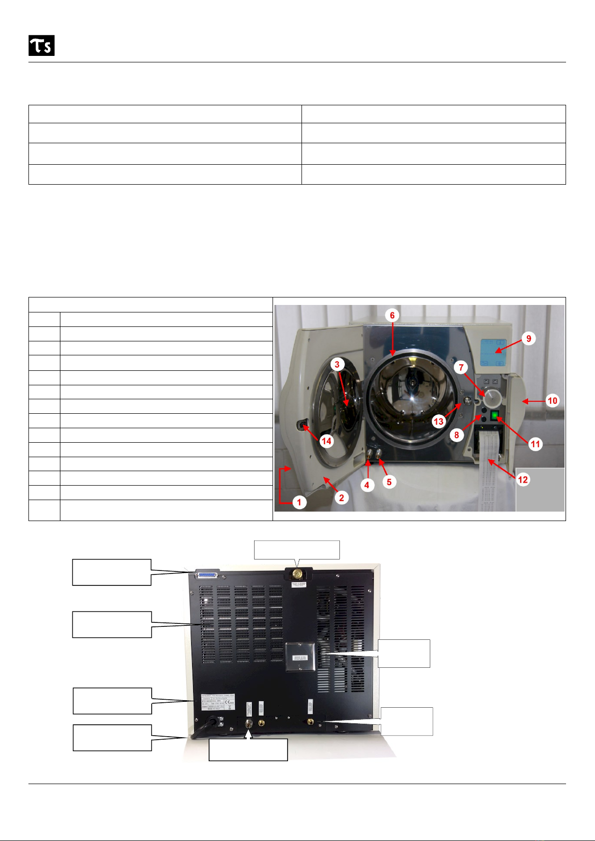
2.1 Items on the front and rear of the autoclave
Fig. 2
Fig. 3
Description Effect
System to regulate the pressure in the event of anomalies
during the sterilisation cycle.
Automatic re-balancing of the pressure inside the sterili-
sation chamber.
Process parameter evaluation system.
Microprocessor-managed.
Stop and indication with warning message.
Check of the electromechanical components before, during
and after operation of the autoclave.
Stop and indication with warning message.
Legend
1Door
2Inner door casing
3Door disk
4Used water drainage
5Clean water drainage
6Door seal
7Bacteriological filter
8Protection fuses (F1 e F2) 6,3x32 T 15 A
9Touch-screen display
10 Display panel door
11 Main switch
12 Printer
13 Door closing motor spindle
14 Door closing motor spindle engagement
housing
Safety valve
EN 13060
Inspection
Steam
outlet
External printer
connector
Heat exchan-
ger
Type Plate
Supply cable
Automatic wa-
ter fill

TAU STERIL N° 11 - Rev. 3 03/02/20
User Manual Page 8 FAST B
3Transport - Installation and preparation for commissioning of the autoclave
The device is packed in the following manner:
Two caps of polyethylene (top and bottom) ,protected by a box around the volcano in triple wave.
Do not lift the machine with violent jerks and not flip.
The device and the packaging are delicate, handle with care. Carry no shock, impact. Store in a dry and protected. The
packaging should be stored.
Using a different packaging, it could cause damage to the product during shipment.
The appliance must be extracted with the help of two people.
- Remove the top cap.
- Extract the machine in two people simultaneously, taking care to keep it always in a horizontal position.
- Place the unit on the worktop.
- The device must be installed inside a laboratory accessible only to authorized personnel.
- Avoid placing the autoclave near sources of steam or splashing with water that may damage the internal electronics.
- Do not install in places with poor ventilation.
- Do not place it near heat sources.
Carefully remove the device from its packaging and check that it is intact. Ensure that the electrical installation is cor-
rectly earthed. Install the autoclave on a flat, horizontal surface to facilitate good ventilation. Do not place the autoclave
closer than 10 cm from walls and other equipment to allow for good ventilation.
To incline the machine, it is generally supplied with two wedges under the front feet: do not, on any account, touch
these wedges.
Do not place any object or obstruction near the opening radius of the door of the autoclave in order to allow this to
open correctly.
Ensure that the supply voltage indicated on the type plate corresponds to that available at the place of installation
(maximum variation of mains voltage: ± 10 %).
Insert the plug in the mains socket. Press the main switch (position “I”) and check that it lights. Failure to comply with
the above relieves TAU STERIL of any responsibility.
Rear view of the autoclave for connection of the pipes supplied:
Legend:
1. Quick connection for demineralised water filling pipe (do not crush the pipe).
2. Clean water outlet connection (do not crush the pipe): keep tank empty.
3. Used water outlet connection (do not crush the pipe): keep tank empty.
From the autoclave chamber, remove the basket, the trays and the accessories supplied (see Appendix 9).
At the rear of the machine, you will find the connections to which must be attached the respective pipes for filling with
water (1) and venting of the two tanks (2 - 3).
Fig.4
TAU STERIL N° 11 - Rev. 3 03/02/20
User Manual Page 9 FAST B
Caution: It is recommended before using the autoclave with load (first load water happened) of
looping "135 ° C Standard" (empty chamber without load) in order to sterilize the chamber.
Please connect correctly the pipes supplied to the drawing Fig. 4.
In case of problems contact the Tau Steril.
IMPORTANT: As can be seen from Fig. 4 there are two plastic cans; one filled with demineralized water from 5-10 liters
(larger preferred, serves for loading automatic water), and an empty (from 5-10 liters larger preferred) for the discharge
of steam (to be maintained always empty).
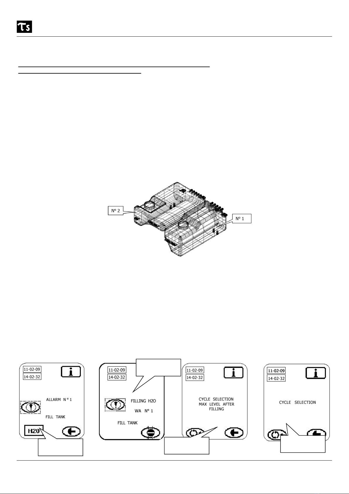
3.1 Description of demineralised water tanks
The autoclave is equipped with two separate tanks:
- clean water, capacity 4.7 litres
- used water = capacity 3.8 litres.
The right-hand tank (No. 1), the clean water tank, contains demineralised water for the cycles. It is equipped with a
sensor with two sensing levels: minimum level, 1 litre, and maximum level, 4.6 litres.
The left-hand tank, the used water tank” contains the water pumped out at the end of the sterilisation cycle. It is
equipped with a sensor: maximum level, 3.7 litres.
The consumption of water per cycle varies according to the material to be sterilised and the weight of the load. The
capacity of tank 1 (clean water) is sufficient for at least 6 sterilisation cycles (see Appendix 1 consumption of water per
cycle).
3.2 First— filling with demineralised water and drainage of the used water tank
Once the machine is correctly installed (section 3), you must fill it with demineralised water (which is used for opera-
tion of the autoclave). The appliance is equipped with an automatic pump.
Below are the windows shown on the touch-screen for filling the autoclave tank:
Note: before pressing on the H20 icon for filling w ith w ater, ensure that the dem ineralised w ater tank is
still full (fig. 4). Each time that you check this tank, empty the steam outlet tank: this tank should ideally be emptied
frequently (at least once every 3 sterilisation cycles).
Fig. 5
During filling
Press on this
icon to fill H2O
End of water
filling
Autoclave rea-
dy for use

TAU STERIL N° 11 - Rev. 3 03/02/20
User Manual Page 10 FAST B
Emptying used water: when alarm No. 2 is shown (see screen page below), insert the pipe supplied into the drainage
connection (see Appendix 9 -Figs. 2 and 6). The used water tank will then start to empty. It may be that alarm 1 is
shown at the same time: if so, press on the fill H20 button. The 2 operations of filling with clean water and emptying
used water can be carried out at the same time with no problem.
4Operation
4.1 Desciption of touch-screen icons
The autoclave is equipped with a touch-screen for the management of the commands and messages used during its
normal operation. Below, you will find a brief description of the icons shown on the screen:
No. Icon drawing Name Use
1Cycle selection To access the sterilisation cycle menu.
2Access main menu To access the machine menu.
3Exit main menu To exit the machine menu.
4
Stop To stop a sterilisation cycle.
5Alarm Sounds when the machine goes into an alert condition
for malfunction.
6Attention Signals the presence of an operation or alarm to
which attention is required.
7
Door open Indicates door opening at the end of a sterilisation
cycle.
8Enter button To confirm the selection of a sterilisation cycle.
9End button To exit a main menu window.
Used water
outlet

TAU STERIL N° 11 - Rev. 3 03/02/20
User Manual Page 11 FAST B
No. Icon drawing Name Use
10 Right arrow Move cursor to the right or go to the next window.
11 Left arrow Move cursor to the left or go to the previous window.
12 Down arrow Move cursor down the screen.
13 Up arrow Move cursor up the screen.
14 Info button Access the data of the last sterilisation cycle carried
out (see section 4.7.1)
15
Save To save or reinitialise menu data.

TAU STERIL N° 11 - Rev. 3 03/02/20
User Manual Page 12 FAST B
4.2 Main menu
The autoclave has a menu and sub-menus for managing the appliance. The instruction windows are shown below:
4.3 Description of the main menu
4.3.1 Language
The window of languages available is shown below. Select the one corresponding to the country where the machine is
used:
To exit the
menu
Cursor up
Languages
available
To confirm
selection
Cursore
down
4.3.2 Print data
In this sub-menu, you will find the data printed during the sterilisation cycle on the printer strip:
To exit
To confirm
Letter for-
ward
Letter back
Cursor to the
left
Cursor to the
right
To confirm
Main menu

TAU STERIL N° 11 - Rev. 3 03/02/20
User Manual Page 13 FAST B
4.3.3 Date / Time
This menu item can be used to correct date and time if required:
To confirm
selection
Current day Forward
Number up Number
down Save
Back
To exit
4.3.4 Formats
Sets the formats for the following:
Date : the representation ( 0,1,2)
Time : representation 12 or 24 hours ( 0,1 )
Pressure units: 0 = Bar > 1= Psi
Temperature units: 0 = degrees Celsius “C” > 1 = degrees Farenight “F”
Number up Number down
To confirm
selection
Save
Forward
Back

TAU STERIL N° 11 - Rev. 3 03/02/20
User Manual Page 14 FAST B
To exit
4.3.5 Internal printer
Use this item to turn the internal printer on or off:
To change To change Save
To confirm
selection
4.3.6 Screen
Use this item to adjust the contrast of the touch-screen.
To confirm
selection
Contrast up Contrast
down Save
TAU STERIL N° 11 - Rev. 3 03/02/20
User Manual Page 15 FAST B
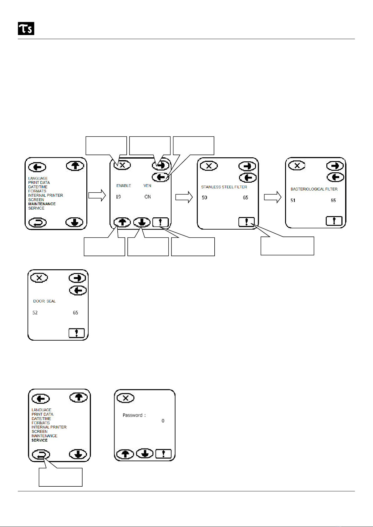
4.3.7 Maintenance ( enable / disable VEN phase)
In this sub-menu, you can enable/disable the VEN phase (anti-condensation ventilation) section 4.7.1.
It indicates to the user when a component of the machine must be cleaned and/or replaced. In this sub-menu, there is
the possibility to reset (after checking/replacing/cleaning the components listed below):
Enable / disable VEN phase ( anti-condensation ventilation see section 4.7.1 )
Stainless steel filter cycle counter
Bacteriological filter cycle counter
Door seal cycle counter
To exit Forward Back
To change To change To confirm
4.3.8 Service
In this sub-menu, you will find all the information useful for technical assistance.
To confirm
selection
To reinitialise the
cycle counter

TAU STERIL N° 11 - Rev. 3 03/02/20
User Manual Page 16 FAST B
4.4 Cycle menu
TYPE OF CYCLE
STERILISATION CYCLES TEST CYCLES
CYCLE B
135° Standard
CYCLE B
135° Prion
CYCLE B
122° Standard
B & D /
Helix
VACUUM
TEST
Temperature 135,5° C 135,5° C 122,5° C 135,5° C -
Pressure 2,16 bar 2,16 bar 1,16 bar 2,16 bar - 0.85
Duration of sterilisation phase 4’ 18’ 15’ 4’10’’ 16’
Drying time 15’ 15’ 20’ 4’ -
Cycle time empty - full load 30’ - 40’ 44’ - 54’ 50’ - 60’ 28’ 24’
TYPE OF CYCLE
Compact, solid objects
(probes, tweezers, drill bits) YES YES YES
Test cycles
See Appendices
4, 5, 6
Small objects / porous materials
(gauzes, cotton, etc.) YES YES YES
Full load, porous materials
(80 % of useful space) YES YES YES
Hollow bodies type A
(hand tools, tweezers, scissors, …) YES YES YES
Hollow bodies type B
(canullae...) YES YES YES
Not packaged, single / double pack-
aged YES YES YES
Maximum load: solid / porous 3.5 / 1,5 Kg 3.5 / 1,5 Kg 3.5 / 1,5 Kg
Materials: the three Class B cycles can sterilise and dry everything: metal, textiles, hollow bodies
A and B, plastic, rubber, in single / double packaging. However
Follow the instructions of the equipment manufacturers
Observe the maximum permitted load as validated by the manufacturer, which guarantees
perfect sterilisation.
The Cycle menu consists of three sterilisation cycles and 3 tests required by the regulatory provisions. The latter are listed and de-
scribed in Appendices 4-5-6.
To go back
Up button
Down button
Access cycle
menu
To confirm
TAU STERIL N° 11 - Rev. 3 03/02/20
User Manual Page 17 FAST B
4.5 Opening/closing door and stopping sterilisation cycle
The autoclave is equipped with a motor to close the access door to the sterilisation chamber (see fig. No. 2).
Important: before closing the door of the autoclave (for a sterilisation cycle), ensure that the door motor spindle is in
a horizontal position. If it is not, turn off the machine at the main switch and turn the spindle through 45° clockwise
(see fig.8 below)
Fig. 7 Fig. 8
Once the position of the motor spindle has been checked (Fig. 8), the machine is ready to start: select the cycle (see
section 4.7), close the door gently until it comes into contact with the spindle: caution! When the door touches the
spindle, exert a gentle pressure: you will then hear the click of a spring that guarantees correct locking of the door.
The cycle can then be started with the appropriate button.
To open the door at the end of the sterilisation cycle or after pressing the Stop icon during the cycle, the door open
icon (see icon page 10, section 4.1) will appear.
In case problems should cause the motor to jam, it is equipped with an unlocking key (see alarms relating to door
motor, see table page 21 and Fig. 7 above). In this case, proceed as follows:
Contact tecnical assistance.
Once the door is closed, you can cancel the operation if you experience a problem (for example, equipment to be
sterilised forgotten, not loaded or badly loaded). This can be done within two seconds after closing the door by press-
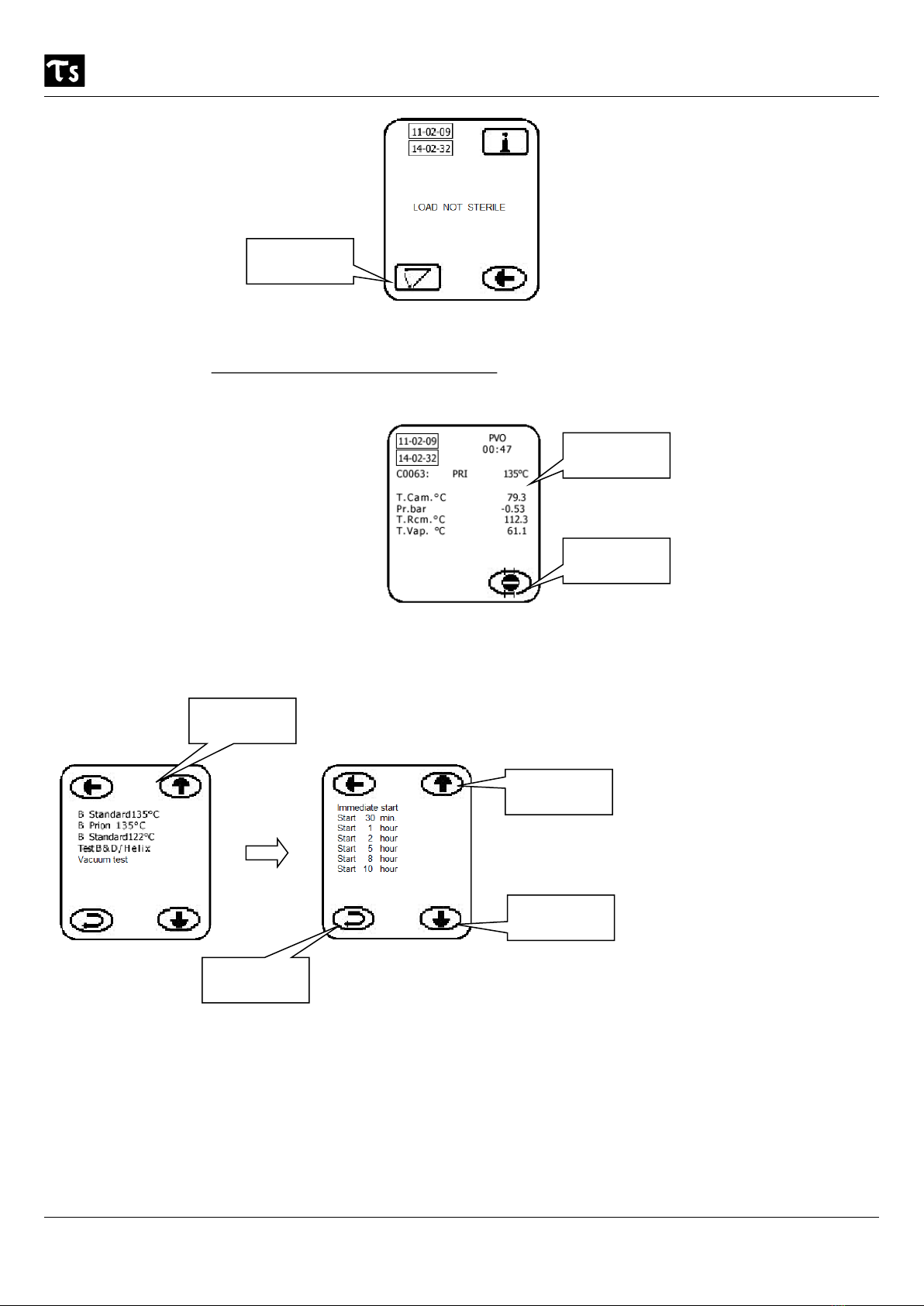
ing the X button (window below). The sequence of windows is as follows:
To cancel
closing
To confirm start
cycle
If you press X, the following window appears:
Unlocking door
T door motor spindle
in horizontal position
TAU STERIL N° 11 - Rev. 3 03/02/20
User Manual Page 18 FAST B
To open the
door
Clearly, the equipment is not sterile as it has not been through the PR Sterilisation phase: the load to be steriliser is
considered sterile if, during the cycle, it passes through the sterilisation phase (PR). If this is not the case, it is consid-
ered "Load not sterile". In this case, restart the sterilisation cycle.
The sterilisation cycle can be stopped at any time by pressing the Stop button.
Cycle running
To stop the
cycle
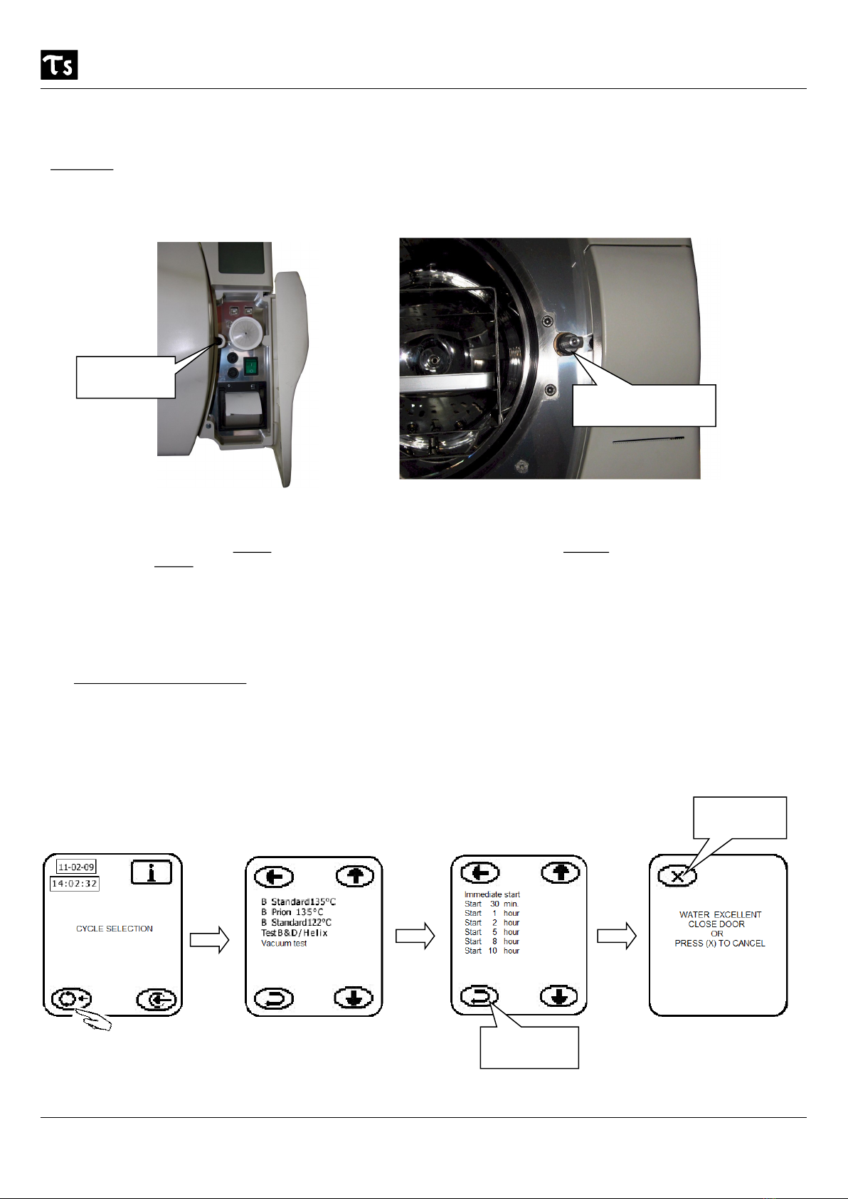
4.6 Delayed start of cycle – overnight cycle
After selecting the cycle from the appropriate menu, the machine indicates the possibility of programming a delayed
start of the sterilisation cycle:
Cycle menu
To confirm
Up button
Down button
After selecting the cycle start option, enter your selection (if you wish the machine to start immediately, select
“Immediate”, using the up and down arrows) by pressing the corresponding button.
If, on the other hand, you wish the machine to run during the night so that the equipment is ready to use in the morn-
ing, proceed as follows:
Enable the ventilation phase VEN (se section 4.3.7, page 15)
Set the delay to, for example, 10 hours: the surgery closes at 20:00 and reopens at 08:00, calculate 1 hour for
the sterilisation cycle, this gives you: from 20:00 to 08:00 is 12 hours, including the ventilation phase, the ma-
chine will start at 06:00 and will finish the sterilisation cycle at 07:00; the ventilation phase will then start to
prevent condensation inside the sterilisation chamber and cool the sterilised equipment.

TAU STERIL N° 11 - Rev. 3 03/02/20
User Manual Page 19 FAST B
4.7 Starting and operating cycle
Preamble: All cycles have the same profile (section 4.4, page16): only the durations of the sterilisation and drying
phases and the sterilisation temperatures (122 °C - 135 °C) differ (see graph F9). The sterilisation cycle consists of
various phases (shown on the touch-screen display during operation) from beginning to end. There follows the list of
the various phases and their meaning:
Phase name Timing (Fig. 9) and purpose
PV0 - PV1 - PV2 Occur at the beginning of the cycle and alternate with PP phases. Their function is to eliminate residu-
al air from the inside of hollow and porous instruments.
PP1 - PP2 Occur at the beginning of the cycle and alternate with PV phases. Their function is to inject steam
during the phases prior to sterilisation.
PPh Follows the PP & PV phases. Its function is to raise the pressure in the machine and prepare for the
“PR“ sterilisation phase.
PR This is the sterilisation phase. Its function is to sterilise the instruments.
LEV Follows the “PR” phase. The pressure is reduced to that of the outside atmosphere.
DV Follows the “LEV” phase. This serves to dry the (sterile) instruments inside the machine.
END Follows the “DV” phase. End of sterilisation cycle.
VEN Follows the END of cycle (if enabled, otherwise not). Prevents the formation of condensation: over-
night cycle section 4.6 (see also 4.3.7, 4.7.1).
Fig. 9
TAU STERIL N° 11 - Rev. 3 03/02/20
User Manual Page 20 FAST B
WARNINGS: During the process of sterilization TAU STERIL alw ays recom mended to insert in the sterili-
zation chamber of the autoclave (with the material to be sterilized) and an indicator of detection of the sterilization
process (complies with the standard currently in force).
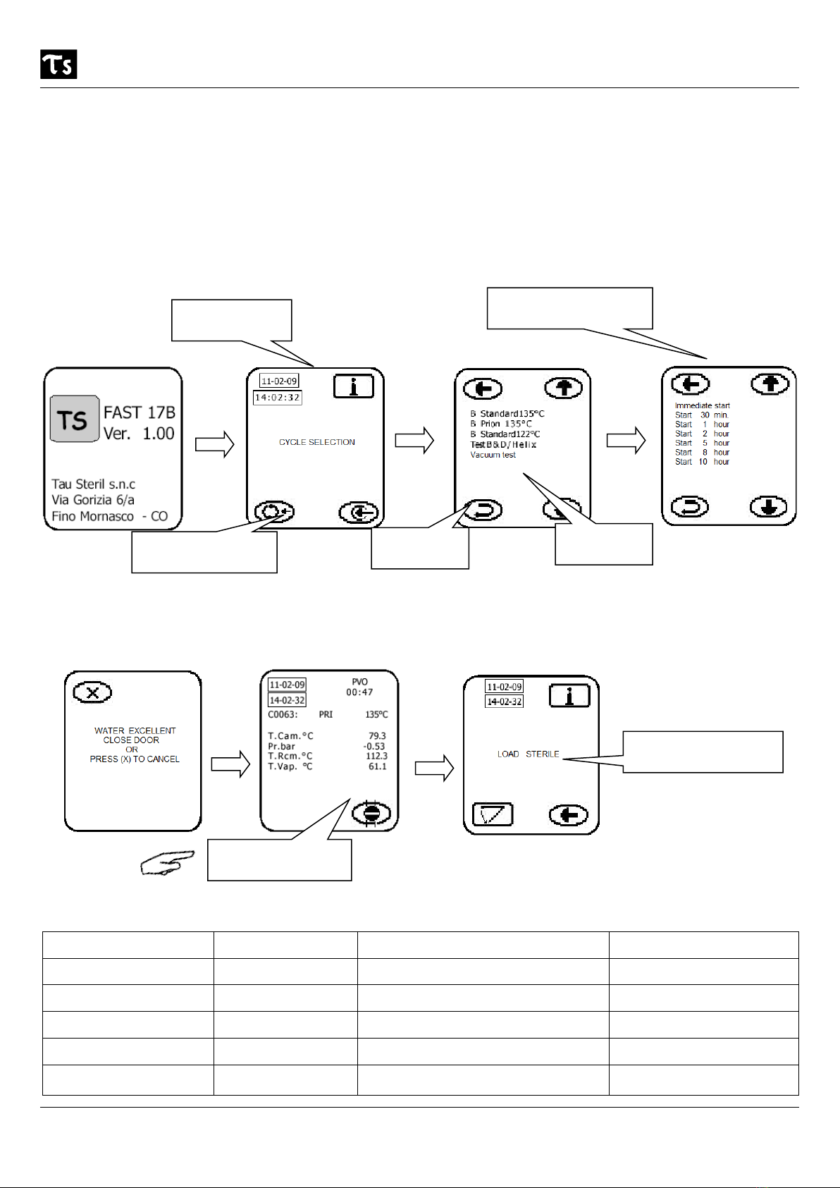
After preparation of the equipment to be inserted in the sterilisation chamber of the autoclave (see Appendix 2), turn
on the main switch (Fig. 2 page 7). In this condition (door open and main switch on) the machine is in Stand-By.
From this point on, to start the machine, work through the following screen pages:
Stand-by condi-
tion
Select start delay and
start
Select the sterilisation
cycle
To confirm
Select the cycle
Close the door ( see section 4.5 ).
Cycle running ***
*** taking this screen page ,as an example, it consist of the following components:
Item indicated Message shown Item indicated Message shown
Date 11-02-09 Chamber heating element temperature T.Rcm.° C = 112.3
Time 14-02-32 Steam generator temperature T.Vap. ° C = 61.1
Sterilisation cycle number C0063 Phase of cycle (duration in minutes Fig. 9) PV0 = 00:47
Chamber temperature °C T.Cam.°C = 79.3 Name of cycle PRI = Prion Test 135°
Pressure Pr.bar = - 0.53
End of sterilisation cycle
Table of contents
Popular Medical Equipment manuals by other brands


Getinge
Getinge Arjohuntleigh Nimbus 3 Professional Instructions for use

Mettler Electronics
Mettler Electronics Sonicator 730 Maintenance manual

Pressalit Care
Pressalit Care R1100 Mounting instruction

Denas MS
Denas MS DENAS-T operating manual

bort medical
bort medical ActiveColor quick guide

AccuVein
AccuVein AV400 user manual


