Tavistock Axiom SAX2341 Parts list manual

Push Button Control Shower Valve
INSTALLATION & AFTERCARE INSTRUCTIONS
Retain for future reference REF: GEN1FCLICKAR.10.19| V1
This guide covers the installation of:
1 Function Push Button Shower Valve

INTRODUCTION
OPERATING CONDITIONS OF USE AND COMPLIANCE
Thank you for choosing this product. This guide covers the installation and commissioning of
the shower valve - for the installation of the associated shower accessories, please see separate
instructions supplied.
This shower valve must be installed in accordance with the Water Supply (Water Fittings) Regulations
1999. We recommend this product should only be fitted by a qualified plumber.
Before installation the operating conditions of use must be checked. The table below contains
details of the necessary conditions of operation. This valve is suitable for high pressure (BS1111)
operating conditions. Valves cannot operate effectively where a hot or cold pressure system crosses
the boundaries of the two ranges. In addition the maximum ratio of unbalanced hot and cold water
pressures for the valves to operate effectively is 2:1. Hot or cold pressure must be reduced or boosted
so as to work within the required range.
These shower valves are suitable for use with all water supply systems up to a maximum of 5.0 Bar.
Operating pressures above 5.0 Bar will require the installation of pressure reducing valves.
The valve must be installed so that it is readily accessible for commissioning and maintenance. The
valve is supplied with isolation valves on both the hot and cold inlets so as to allow the valve to be
commissioned and tested correctly. The valve is fitted with integral check valve cartridges which
command the water supply, therefore the thermostatic valve is protected against cross-flow due to
unbalanced line pressures as required by the Water Supply (Water Fittings) Regulations 1999.
MAX STATIC BAR 10 BAR
1.0 - 5.0
55 - 65
MAX 25
MAX 44
HIGH PRESSURE BS1111
FLOW PRESSURE (BAR)
HOT & COLD
HOT SUPPLY (OC)
COLD SUPPLY (OC)
MIXED WATER (OC)

WHATS IN THE BOX
Before installation please ensure all components are present. The following illustrations can be used as
a guide and used for reference during installation - illustrations are intended as a guide only, style and
sizes vary depending on system chosen.
Installation Frame
Flexible Hoses
Fixing Spanner
Zip Tie
Tile Guide
Fixing Screws
Isolation Valves
(Assembled to Installation Frame)
Cover Plate
Valve and Housing

Horizontal
Horizontal
Vertical
BEFORE INSTALLATION
Before installation, decide if the valve will be installed horizontally or vertically. Both options are
available with this valve and use similar installation methods. This guide shows horizontal installation for
illustrative purposes.
Most problems associated with the operation of thermostatic shower valves are caused by debris in the
new pipe work getting into the thermostat. These problems are easily avoided by thoroughly flushing
the pipe work BEFORE the valve is fitted. Failure to do so may invalidate your guarantee.
This valve is designed to be installed in stud constructions using timber of a suitable depth as to allow
the full installation frame to fit onto the stud (Figure 1). The centre point between the two studs will be
the final position of the valve. To ensure successful installation, the frame needs to fit correctly between
the two studs without deforming the frame. If necessary use spacers to create the correct fit.
Figure 1

1. Position the installation frame between the two studs or noggins at a suitable height for its final
installation position. The front of the frame and the front of the timber stud should be flush (Figure 3).
Use a spirit level placed on the tiling guide to make sure the installation frame is level both front to back
and left to right. Once level remove the tile guide and keep the fixing screws safe for later steps.
For vertical installations, timber noggins should be installed between studwork to allow for the frame to
be fixed vertically. (Figure 2)
When fitting the installation frame in either orientation, keep the tile guide assembled as this will ensure
that the frame does not warp or bend during installation and also allow a spirit level to be used for
accuracy.
Figure 2
INSTALLATION INSTRUCTIONS
Figure 3
Vertical

2. Once the frame is installed, remove the plastic tile guide. Install the supply pipework to the isolation
valve and the brass manifolds. The hot water feed should be installed into the left hand manifold and
the cold water feed to the right hand manifold. Ensure the isolation valves are mounted so that they will
be visible and accessible for later stages (Figure 4).
3.With the water inlet supplies installed, install outlet pipework using suitable plumbing fittings. Ensure
that there is enough room to route pipework to the chosen outlet location.
Figure 4
Figure 5
Brass Manifold
Isolation Valve
These fittings are used with flexible hoses to
connect the valve to inlets and outlets
H
H
C
C

4. Connect the flexible hoses to the manifolds - ensure that each hose has a rubber washer inserted at
each end to create a watertight seal. Once connected, label each hose with the corresponding inlet /
outlet - this will help easily identify which hose is which during later installation stages.
5. At this point it is critical that leak tests are performed. Connect the valve body to the flexible hoses
- the hot and cold inlets are marked with red and blue paint on the valve. Turn on the water supply and
test the system for leaks. Push the button for the outlet and check all connections are fully sealed.
HOT COLD OUTLET 1
Figure 6
Figure 7

6. Once satisfied that there are no leaks, turn the water supply off and disconnect the valve from the
flexible hoses. Before installing plasterboard and tiles, use the zip tie provided to tie the ends of the
hoses together to make them easier to access later.
You are now ready to apply the nal nished surface.
7. Reattach the tile guide using the fixing screws. Cut a hole in the plasterboard using the tile guide to
determine position and sizing.
Tip: There are pins in the corners of the tile guide to help mark its position on the plasterboard to use as
a cutting template.
Figure 8
Figure 9
HOT OUTLET 1
COLD

8. Once a hole has been cut in the plasterboard, secure it to the stud. The tile guide should pass
through the hole in the plasterboard. Tile up to the edges of the tile guide to ensure the correct size
access hole. Failure to do so may mean the cover plate does not form a water-tight seal in later
installation stages.
9. Remove the tiling guide, allowing access to the pipework behind the tiled wall. Keep these screws
safe as they will be used to mount the valve. From this position the isolation valves should be visible
and accessible through the access hole.
Figure 10
Figure 11
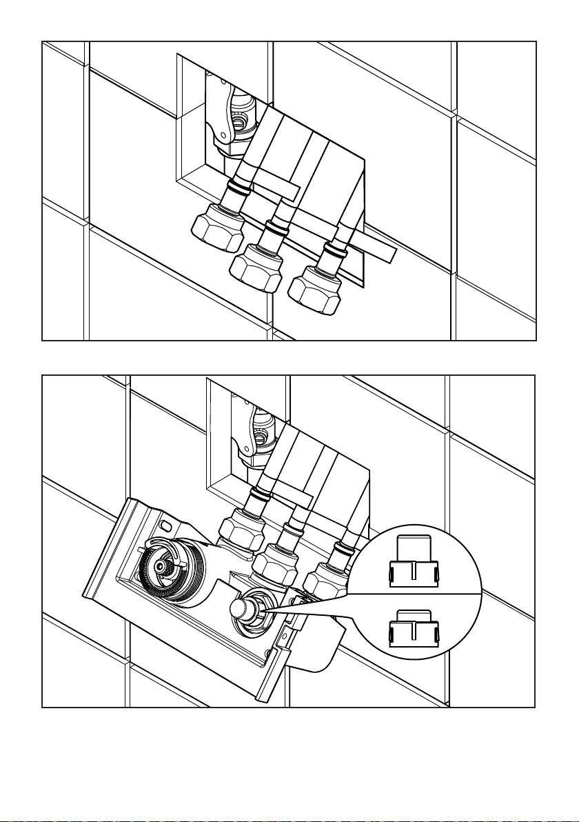
10. Pull the flexible hoses through the access hole in the wall and remove the zip tie.
11. Working from left to right, using the labels as a guide, connect the hoses to the valve. Ensure the
hose from the hot supply is connected to the inlet marked hot on the valve. Do the same for the cold
supply. Ensuring the outlet button is in the ‘OFF’ position (Figure 13), turn the water supply back on at
the isolation valve. Do not overtighten the hoses as this may damage the rubber washers.
Figure 12
Figure 13
OFF
ON

12. Lift the valve and push the hoses back through the access hole, making sure the hoses do not kink
(Figure 14). Position the valve flat against the tiles and line up the fixing holes with those on the metal
installation frame. Secure the valve to the fixing frame.
Note: Tighten xing screws with a screwdriver to prevent over-tightening. Do not use an electric
driver as this may damage the valve housing or cause it to warp, preventing correct installation. If
the housing ange is not at against the wall surface, the xing screws are too tight.
You are now ready to install the cover plate and valve controls.
13. When secured in place, the fixing nuts of the flexible hoses will be visible above the valve housing.
This will allow the connections to be checked for leaks and for the hoses to be tightened slightly, if
necessary, without removing the entire valve.
Figure 14
Housing Flange
Figure 15
Fixing Nut
Button Spring
Button
Remove the brass fixing nut from the back of the cover plate, as shown above. This will allow the etched
button and spring to be removed. Rotate the button 90 degrees and reassemble to the cover plate.
(Figure 16). There are four slots which ensure the button is located correctly. With the spring assembled
inside the channel on the back of the button, reassemble the brass fixing nut.
NOTE: For horizontal installations, the cover plate can be tted immediately - proceed to Step 14.
For vertical installation the control button and temperature stop need to be removed and rotated
so that they are in the correct orientation. To do so, follow the below instructions:
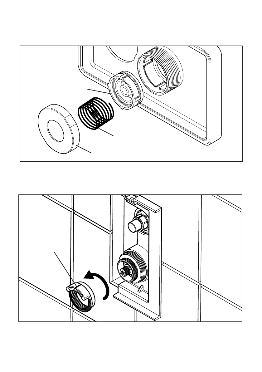
The temperature stop ring is installed onto the temperature cartridge fixing nut on the valve. This
prevents the maximum temperature from being exceeded when in use. For vertical installations the
temperature stop ring needs to be removed and rotated 90 degrees as shown (Figure 17)
Figure 16
Temperature
Stop Ring
Figure 17

14. Position the cover plate over the valve housing and fix in place with the cover plate fixing nut.
Tighten the plate to the wall with the tool provided making sure not to scratch the cover plate. Make
sure the cover plate is level and that the button is in line with those on the valve. The cover plate is fitted
with an integrated foam seal - it is not necessary to use silicone sealant.
You are now ready to set the maximum temperature of the valve.
15. With all outlet buttons checked for smooth operation, using a thermometer, test the temperature
of the water from the outlets. Rotate the cartridge spindle anti-clockwise to increase the temperature
and clockwise to reduce the temperature until the water from the outlet reaches the maximum
recommended temperature of 44ºC. Leave the cartridge spindle in this position.
Figure 18
Figure 19
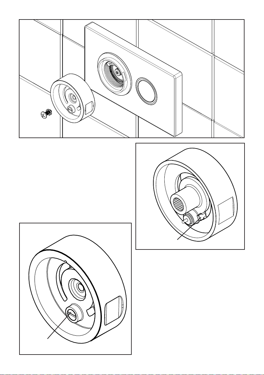
16. On the rear of the handle is a handle stop
that sits against the right hand side of the valve
temperature stop ring to prevent the handle
being rotated past the pre-determined maximum
temperature position. Without moving the
temperature spindle, position the handle onto the
cartridge so that it cannot rotate anti-clockwise.
Note: Do NOT remove the temperature stop ring
to make adjustments as this will prevent correct
assembly later.
17. Once installed, the handle should click as it
rotates. This click can be adjusted to give more
feedback when in use.
Rotating the feedback screw clockwise will
make the pin stiffer and the click will be more
noticeable - rotating the screw anti-clockwise will
loosen the pin and soften the click.
Figure 21
Figure 20
Feedback Screw
Handle Stop

18. With the handle installed, the centre dial can be pushed into place. The dial has a tab that fits into
the temperature stop ring via a gap in the handle. To remove the dial for maintenance, line up the notch
in the centre dial with the notch on the handle and use a small screwdriver to separate the two parts.
Installation is now complete.
Figure 22
TESTING AND ANNUAL SERVICING
It is recommended that showers do not exceed 44°C. The valve temperature should never exceed
46°C. After commissioning, carry out the cold failure test to ensure the valve operates at the correct
outlet temperature.
The valve should be tested to ensure correct operation during installation and thereafter at stated
intervals decided by the user but never at greater than 12 monthly intervals. The testing will only require
a normal thermometer with a scale greater than 65°C. The temperature sensitive element of the
thermometer should always be fully inserted into the water flow.
Follow the procedure below:
1. Measure the mixed water temperature.
2. Carry out a cold fail/safe shut-off test by using the mains isolation valve to shut off the water to the
cold supply. Wait 5 seconds, if water is still flowing check that the water temperature is below 44°C.
The flow should stop or reduce to a trickle.
3. Open the cold water isolation valve and measure mixed water temperature. If there is no significant
change from the original settings and fail/safe shut off is functioning the valve is working correctly and
no further service is required. If the outlet temperature has drifted by more than 2°C, or if the fail/safe
function does not work, a full service or re-commissioning is required. We recommend that in these
circumstances you contact a plumber.

TROUBLE SHOOTING
If you require further assistance beyond the guide below, including replacement parts, please contact
customer services using the contact details on the back of this guide.
PROBLEM
After installation, shower only runs Hot or Cold -
there is no mixed water.
Shower will not run hot enough when first
installed.
Cold water is running back through the valve
and into the hot water system.
SOLUTION
Check and clean the check valves located on
the hot and cold inlets on the valve. These may
need to be replaced.
The maximum temperature needs to be
adjusted - see the temperature setting guide in
this manual.
Hot & Cold supplies are plumbed the wrong
way around. Remove the valve from the wall and
check the plumbing connections to the valve.
The valve does not turn on even when the
button is pressed.
The button operation is not smooth and
sometimes scrapes.
In some cases this may be caused by over-
tightening the cover plate during installation
which can cause the buttons to become
partially pressed. Loosening the cover plate
fixing nut slightly should fix this.
Remove the cover plate and reassemble
ensuring that the valve buttons and cover plate
are correctly aligned to avoid interference.
Check you have correctly turned the isolation
valves to the ‘on’ position for both the hot and
cold supplies.
There is no water running to the valve
Customer Services, Brassmill Lane Trading Estate, Bath, BA1 3JF
Tel:01225 303 900
This manual suits for next models
3
Table of contents
Other Tavistock Bathroom Fixture manuals


Popular Bathroom Fixture manuals by other brands


LOOOX
LOOOX PILLAR ROUND user manual

Hans Grohe
Hans Grohe Verso 220 Showerpipe 27237000 Instructions for use/assembly instructions

Kohler
Kohler K-17493 Installation and care guide

BELLOSTA
BELLOSTA via dei condotti B3-120/D installation instructions

Gessi
Gessi OUTDOOR 63204 manual

WimTec
WimTec SanRec SMART Installation and operating instructions