TAVRIDA ELECTRIC ISM Shell_2 Series Instructions for use

ISM Shell_2 Series
Vacuum Circuit Breaker
15kV, ...29kA, ...2000A
Applications Manual MAN5002239
Revision 4

2

3
Safety rst
· Check whether the installation position (distances, spatial separation, and the
surroundings) is suitable for the switching devices.
· Installation, operation and maintenance shall only be carried out by trained and
experienced personnel who are familiar with the equipment and the electrical
safety requirements.
· During installation, commissioning, operation and maintenance of the equipment
the relevant legal regulations, accident prevention regulations and the connecting
conditions of the electric utilities shall be followed.
· Take note that during operation of the vacuum circuit breakers certain parts are
subject to dangerous voltage. Mechanical parts, also remote-controlled, can move
quickly. Failure to comply may result in death, severe personal injury or damage
to equipment.
· Pay attention to the hazard statements located throughout this manual.
· The operating conditions of the vacuum circuit breakers shall comply with
the technical data specied in this manual.
· Personnel installing, operating and maintaining the equipment shall be familiar
with this manual and its contents.
For special congurations please contact TAVRIDA ELECTRIC NA.
The following installation and operating Instructions contain information necessary
for the methods of use, installation, commissioning and operation. It is absolutely
necessary for the proper use of the vacuum circuit breakers to read the Installation
and Operating Instructions carefully before starting and to adhere to the instructions
and the relevant regulations.

4
1
2
3
4
Table of Contents
1. Introduction
• Applicability ....................................................................................................................................................................................................8
• Hazard Statements.......................................................................................................................................................................................8
• Safety Instructions........................................................................................................................................................................................8
• Denitions.........................................................................................................................................................................................................9
• General ...............................................................................................................................................................................................................9
• Design and Method of Operation: ISM and CM ..................................................................................................................... 10
2. Receiving, Handling and Storage
• Packing ........................................................................................................................................................................................................... 14
• Transport ....................................................................................................................................................................................................... 15
• Unpacking, Receiving Inspection..................................................................................................................................................... 15
• Rating Plates, Warranty Seals .............................................................................................................................................................. 16
• Storage............................................................................................................................................................................................................. 18
3. Installation
• General, Preparation ................................................................................................................................................................................ 20
• Installation of the ISM.............................................................................................................................................................................. 20
• Minimum Clearances due to Rated Insulation Voltage........................................................................................................ 22
• Minimum Clearances due to Electromagnetic Inuences.................................................................................................. 23
• Coordination of Minimum Clearances .......................................................................................................................................... 23
• Heating ............................................................................................................................................................................................................ 23
• Protective Grounding.............................................................................................................................................................................. 23
• Interlocking ................................................................................................................................................................................................... 24
• Main Contacts Position Indicator...................................................................................................................................................... 26
• Secondary Connections of the ISM ................................................................................................................................................. 29
• CM connections.......................................................................................................................................................................................... 30
• CM_16 Series Factory Programmable Options......................................................................................................................... 32
• Installation of the CM .............................................................................................................................................................................. 34
• Installation of Secondary Cables between ISM and CM...................................................................................................... 35
4. Switching and Control Functions
• Charging of the Capacitors................................................................................................................................................................... 38
• Ready-LED and Ready-Relay Output .............................................................................................................................................. 38
• Malfunction-LED and Malfunction-Relay Output.................................................................................................................... 38
• Switching the ISM On and O via the Dry Contact ............................................................................................................... 38
• Inputs of the CM......................................................................................................................................................................................... 38
• Electrical Closing Lock-Out................................................................................................................................................................... 38
• ISM Forced Trip by an Undervoltage Relay (Optional - CM_1501 Series)................................................................... 39
• Output to Magnetic Actuator and Input for ISM Position Indication........................................................................... 39
• Operations Counter.................................................................................................................................................................................. 39
• Antipumping Duty.................................................................................................................................................................................... 40
• Blocking Duty............................................................................................................................................................................................... 40
• Combined Blocking ................................................................................................................................................................................. 40
• and Antipumping Duty .......................................................................................................................................................................... 40
• Output to Magnetic Actuator and Input for ISM Position Indication........................................................................... 40
5. Commissioning, Maintenance

5
5
6
7
8
9
10
11
12
• General............................................................................................................................................................................................................. 42
• Commissioning Primary Part............................................................................................................................................................... 42
• Commissioning Secondary Part ........................................................................................................................................................ 42
• Maintenance................................................................................................................................................................................................. 43
• Non-Conformity.......................................................................................................................................................................................... 43
6. Signalling
• LED Indicators and Dry Contacts ...................................................................................................................................................... 46
• Malfunction Indication Table .............................................................................................................................................................. 47
7. Special Applications: Fast Switching
• Fast Transfer Switching ........................................................................................................................................................................... 50
• Arc Flash Mitigation.................................................................................................................................................................................. 51
8. Product Line
• Indoor switching modules (ISM)....................................................................................................................................................... 54
• Control modules (CM15 Series) ......................................................................................................................................................... 54
• Control modules (CM16 Series) ......................................................................................................................................................... 54
9. Dimensions and Weights
• Dimensions and Weights of the ISM ............................................................................................................................................... 56
• Dimensions and Weights of the CM................................................................................................................................................ 59
• Dimensions of the Position Indicator............................................................................................................................................. 60
• Dimensions of Mating Part for Interlocking Shaft................................................................................................................... 60
10. Circuit Diagrams
• ISM15_Shell_2 with CM_1501_01.................................................................................................................................................... 63
• ISM15_Shell_2 with CM_16_1............................................................................................................................................................ 64
11. Technical Data
• Indoor Switching Modules (ISM)....................................................................................................................................................... 67
• Control Modules......................................................................................................................................................................................... 68
12. Regulations and Ambient Conditions
• Regulations.................................................................................................................................................................................................... 73
13. Legal Information
• Warranty.......................................................................................................................................................................................................... 75
• Quality Regulations .................................................................................................................................................................................. 75
• Complaints and .......................................................................................................................................................................................... 75
• Transport Damage..................................................................................................................................................................................... 75
• Environmental Friendliness.................................................................................................................................................................. 76
• Non-Conformity Report......................................................................................................................................................................... 76
• Liability............................................................................................................................................................................................................. 76
• Copyright........................................................................................................................................................................................................ 76

6
1THIS PAGE INTENTIONALLY LEFT BLANK

7
Introduction 1

8
Applicability
This Technical Manual applies to a range of Indoor Circuit Breakers (ISM) manufactured by Tavrida Electric.
The following products are covered by this manual:
ISM15_Shell_2(150)
ISM15_Shell_2(210)
ISM15_Shell_2(275)
The model number is shown on the equipment rating plates. If your equipment does not correspond to this number then
this manual is not applicable. Please contact your nearest Tavrida Electric oce.
Every care has been taken in preparation of this manual. However, please note that not all the details or variations
in the equipment or process being described can be covered. Neither is it expected to address all contingencies
associated with the installation and operation of this equipment. For any further information please contact your nearest
Tavrida Electric oce.
Hazard Statements
This manual contains three types of hazard statements, as follows:
DANGER: Indicates an imminently hazardous situation that, if not avoided, will result in death or serious
injury.
WARNING: Indicates a potentially hazardous situation that, if not avoided, could result in death or serious
injury.
CAUTION: Indicates a potentially hazardous situation that, if not avoided, could result in personal injury
or equipment damage.
Safety Instructions
General hazard statements applying to this equipment are described in this section. Statements relating to specic tasks or
procedures are located throughout this manual.
DANGER: Contact with hazardous voltage will cause death or severe personal injury. Contact with Recloser
or Control Cubicle terminals should only be undertaken when equipment is isolated from
applicable sources of voltage.
WARNING: This equipment is not intended to protect human life. Follow all locally approved safety
procedures when installing or operating this equipment. Failure to comply may result in death
or severe personaly injury.
WARNING: Before working with equipment descriped in this manual carefully read and understand the
contents of this manual. Improper handling, installation, operation or maintenance can result
in death, severe personal injury or demage to equipment.
WARNING: Power distribution equipment must be properly selected for the intended operation. It must be
installed, used and understand all relevant safety procedures. Failure to comply can result in
death, personal injury or equipment damage.
1

9
Denitions
The following abbreviations are used in this operating manual:
AR Automatic reclosing
CM Control module
CO Close open cycle
ISM Indoor switching module
LED Light emitting diode
MCB Miniature circuit breaker
Make time
The make time is the time period from the energising of the closing circuit to the time when the current begins to
ow in the rst pole.
Closing time
The closing time is the time period from the energising of the closing circuit to the time when all three poles make
contact.
Pre-arcing time
Interval of time between the initiation of current ow in the rst pole during a closing operation and the instant
when the contacts touch in all poles for three-phase conditions or the instant when the contacts touch in the
arcing pole for single-phase conditions.
Opening time
The opening time is the time period from energising of the closing circuit up to the time when all the switching
poles are separated.
Break time
The break time is the time period from the energising of the closing circuit up to the time when the arcs of all the
poles are extinguished.
Open-close time (during AR)
Interval of time between the instant when the arcing contacts have separated in all poles and the instant when the
contacts touch in the rst pole during a reclosing cycle.
Dead time (during AR)
Interval of time between nal arc extinction in all poles in the opening operation and the rst reestablishment of
current in any pole in the subsequent closing operation.
NC Normally closed contact
NO Normally open contact
PCD Pole center distance
SCADA Supervisory control and data aquisition
VCB Vacuum circuit breaker
VI Vacuum interrupter
General
In comparison to conventional circuit breakers, the Tavrida Electric vacuum circuit
breakers comprise of two components:
· The ISM (Figure 1)
· The CM for controlling the ISM and monitoring both modules (Figure 2)
Both modules must only be operated together and are meant for indoor
installations only. The possibility to choose ISM and CM separately allows any type
of switchgear to be easily equipped with regard to its primary and auxiliary circuits.
Figure 1
Figure 2
1

10
Compact design
Tavrida Electric develops and produces all vital parts of the circuit breakers themselves. The result of intensive
inhouse fundamental and material research are extremely compact vacuum interrupter and magnetic actuators.
Optimal selection of all components makes these the most compact and light weight vacuum circuit breaker in
the world.
Long life
Contact erosion is minimised by use of axial magnetic eld. All the switching elements are assembled axially and
symmetrically in one straight line. This means that all the mechanical movements are exclusively direct and linear.
30 000 operating cycles can be achieved with rated current without replacing or adjusting any components.
Maintenance free
The ISM is maintenance-free over the expected life of at least 25 years.
Highest availability
In addition to minimising the number of failure-critical components, the Tavrida Electric circuit breaker monitors
its status continuously. In the unlikely event that a fault occurs it is indicated and can be rectied before an unsuc-
cessful switching attempt is made. This leads to higher availability of the electric power supply system.
Design and Method of Operation: ISM and CM
The ISM vacuum circuit breaker uses three single-coil magnetic actuators, one per pole. The three actuators are
mounted in a steel frame and mechanically linked by a synchronizing shaft (Figure 3).
1. Support insulator
2. Upper terminal
3. Vacuum interrupter
4. Movable contact with bellows
5. Lower terminal
6. Pulling insulator
7. Actuator stator
8. Opening and contact pressure springs
9. Actuator coil
10. Actuator armature
11. Synchronizing shaft
12. Auxiliary contacts
13. Interlocking shaft
14. Main contacts position indicator link
15. Frame
16. Fixing points
Figure 3
View into the ISM
Indoor Switching Module (ISM)
1
2
3
4
6
7
10
13
5
14
15
12
11
16
8
9
1
1. Terminals
2. LED indicators
3. Fastening holes
4.
Grounding stud
Control Module (CM)
3
2
1
Figure 4
Control Module

11
Closing
In the open position the contacts are kept open by the force of the opening springs. To close the contacts
the coils of the magnetic actuators are excited by a current impulse of the close capacitors of the CM. As a
result the contacts close. At the same time the opening springs are compressed. In the closed position the
contacts are kept closed by means of the magnetic force only. The ISM maintains the closed position
without mechanical latching also in case of a failure of the auxiliary power supply (Figure 5).
Opening
To open the contacts a current impulse in the reverse polarity derived from the opening capacitors of the
CM is injected in the coils of the magnetic actuators releasing the magnetic holding force. The compressed
opening springs and contact pressure springs open the contacts (Figure 5).
Manual-Emergency-Tripping
The ISM can be tripped mechanically without auxiliary power supply (emergency trip). It may be opened
manually by means of interlocking shaft rotating counter-clockwise. The interlocking cam of interlocking
shaft act on the armature, when then starts to move (refer to chapter“Installation/Primary part/
Interlocking”, page 24). As the air gap increases, the opening springs and contact pressure springs
overcome any magnetic holding force and the module opens.
Manual Closing
The ISM can only be closed electrically via the CM. In the case of a failure of auxiliary power supply the
contacts can be closed using an alternative auxiliary power supply such as a battery. Mechanical closing is
not possible and leads to the destruction of the ISM.
Position main
contacts
Actuator coil
current
Anchor travel
Anchor velocity
Open
Closed
Open
Closed
0
0
0
Close command CM (dry contact)
Close impuls to ISM-coils
Start anchor movement
ISM main contacts closed
Stop anchor movement
Switch o actuator
current for close operation
Trip command CM
(dry contact)
Trip impuls to ISM-coils
ISM main contacts open
Open position kept by
opening springs
0 20 40 60 80 100 120 140 160
Time (ms)
Figure 5
Typical oscillograms of ISM operation
1

12
1THIS PAGE INTENTIONALLY LEFT BLANK

13
Receiving, Handling and
Storage
2
14
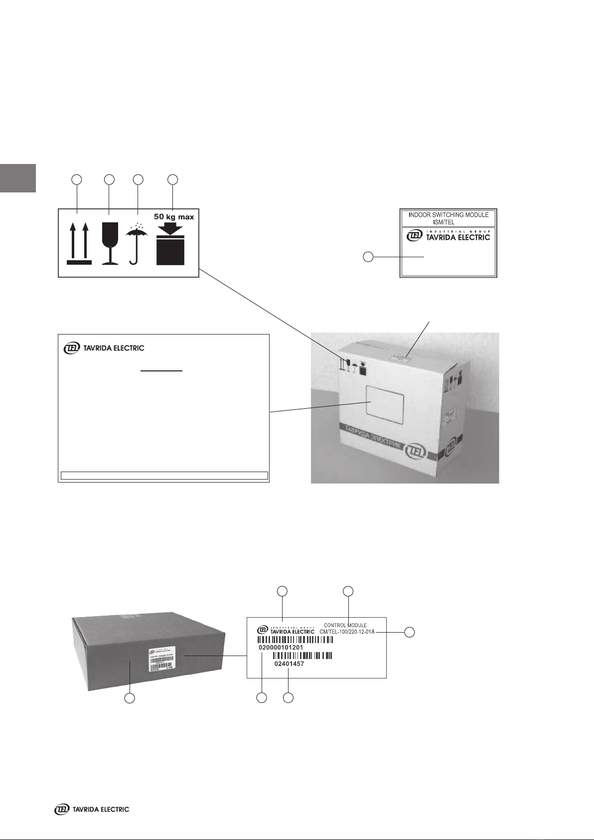
Packing
The following information are provided on the ISM packing cartons (Figure 8):
· Handling symbols for transport and storage of the delivery unit (Figure 6)
· Label 1 for manufacturers´ and product information (Figure 7)
· Label 2 for logistics data (Figure 9)
35522
Figure 6
Handling symbols
Figure 7
Label 1 for manufacturers´
and product information
Figure 8
ISM carton package
Figure 9
Label 2 Logistics data
3 421 1. This side up
2. Fragile
3. Protect from rain
4.
Max. weight on
the delivery unit
5. Serial number
5
A label with the following information is xed on each CM carton package (Figure 10).
1 2
3
4
5
6
1. Manufacturer
2. Product name
3. Type of device
4.
Serial number
5. Product code
6.
Carton package for
CM/TEL…-12-01A
(265x220x55 mm)
A CM carton package must not have a weight of more than 30 kg applied to it.
Figure 10
CM carton package and label
17.10.2006
Mark: TEG-C-000111
Place of delivery:
Consignee:Address
Address
Address
Address
Address
Phone:
Contact person
P/O Number: Customer reference
Article: Article description
Serial Number:
TAVRIDA ELECTRIC AG, Wetterkreuz 3, 91058 Erlangen, Germany,Phone: 0049-9131-972079-0
Consignee:
35522
2

15
Transport
ISM and CM shall be transported in the original packing only. The packed goods shall be handled in accordance with
the handling symbols. Loading procedures for ISM packing units shall be carried out only with fork lifts or cranes.
If possible the ISM packing unit shall be placed on a palette. Lifting gear must not be attached to the support
insulators. During transportation the ISM and CM must not be hit or dropped.
Unpacking, Receiving Inspection
Before unpacking, please check the carton for damage and dampness. Removal of the products from the original
packing must be carried out with due care. Every ISM and every CM shall be subject to a completeness control.
Scope of delivery for the ISM:
ISM Screwdriver Operating manual Routine test certicate
1x
Main contacts position indicator.
Length of exible link is 1,0 m.
AXCA. 305449.002
Figure 11
Insulating caps optional
6x
AXCA . 757559.014, for contact arms with 50mm
diameter, lenght of the insulation cap is 176 mm
6x AXCA . 757559.015 for contact arms with 74 mm
diameter
6x
AXCA . 757559.016 for contact arms with 50 mm
diameter, lenght of the insulation cap is 203 mm
2

16
2
Scope of delivery for the CM:
CM Screwdriver Routine test certicate
Figure 12
The devices should be checked visually for:
· Mechanical damage, scratches, discolouration, corrosion
· Damage to the seals (Figure 17, Figure 18)
Any transport damage must be reported immediately to the carrier in writing.
Cases of damage must be photographically documented.
Rating Plates, Warranty Seals
Please check that the rating plates of the delivered devices correspond to the data of the order. The rating plate
for the ISM contains the following information (Figure 13):
1. Manufacturer
2. Type of device
3. Rated maximum voltage
4.
Rated impulse withstand voltage
5. Rated dielectric withstand voltage
6.
Rated frequency
7. Single capacitor bank breaking
current
8.
Cable charging breaking current
9. Year manufactured
1
2
3
4
5
6
9
10
Figure 13
Rating plate
7
8
11
12
13
14
15
16
17
18
10.
Rated operating sequence
11. Applicable ANSI stan-
dards
12. Rated continuous current
13. Rated short circuit current
14. DC component percen-
tage
15. Rated short time current
16. Interrupting time
17.
Pole centre distance
18. Weight

17
2
The rating plates for the CM1501 series contain the following information (Figure 14):
Breaker Control Module
Model CM_16_1(60)
Power Supply Input
19-72
25 W for 10s (charging)
5 W steady state
Input must be
protected by a two pole
miniature circuit breaker
rated: 4A, type B or C
Fault / Ready Relays
Max 240 16A
See circuit breaker
applications manual for
detailed information and
DC load break capacity.
Operating Conditions
-40C to +55C ambient
IP40 degree of protection
Operating Duty
O-0.3s-CO-10s-CO-10s
Conforms to
UL STD 508
Certied to
CAN/CSA-22.2 No.
142-M1987
Tavrida Electric North America
1105 Cliveden Ave, Delta, BC, Canada
1-866-551-8362
Made in Russia
4000068
1
2
3
4
5
4
6
7
8
9
1. Model type
2. Auxiliary power supply min / max
3. Power consumption
4.
Warning notes
5. Output contact maximum voltage / current
The rating plate for the CM16 series contain the following information (Figure 15):
1
2
3
4
5
6
7
8
9
The CM_16 has an additional label for factory programmable settings (Figure 16); see page 32 for detailed
information on the settings functions.
1
2
1. Settings
2. QR code (scannable settings code)
3. Applicable breaker type
3
6.
Operating conditions
7. Operating duty cycle
8.
NRTL listing / conformance mark
9. Contact information
Figure 14
Figure 15
Figure 16

18
3
Arrangement of the labels (Figures 16, 17):
3 1 2
ISM
1. Rating plate
2. Serial number
3. Seal
CM
1.
Seal
2. Serial Number, date of manufacturing
3.
Product code
Figure 17
Labelling ISM
Figure 18
Labelling of the CM_16
The manufacturer accepts no warranty for a device if the seal is broken or has been removed.
Storage
Should immediate installation not be possible, the ISM and CM shall be stored in the original packing under the
following conditions:
· The ISM is switched o.
· Dessicants must be placed in the packing.
· Storage must be dry, well ventilated and the room temperature should be between - 40°C and + 40°C
(IEC694/ DIN VDE 0670 Part 1000).
· If several ISM are stacked a maximum of two layers is permitted.
· If several CM are stacked a maximum of 10 vertical layers is permitted.
If CM are stored longer than one year, the built-in capacitors shall be charged according to the following procedure before
putting into operation:
· Switch On auxiliary power supply to CM for 20 seconds.
· Switch O auxiliary power supply to CM for one minute.
· Repeat the described switching on and o procedure two times.
· Switch On auxiliary power supply to CM for at least 8 hours.
2
3
1

19
Installation 3

20
Primary part
General, Preparation
The following regulations must be adhered to during installation, commissioning and operation:
· IEC 60694/DIN VDE 0101, General specication for high-voltage switchgear and control gear standards.
· VDE 0105, Operation of electrical installations.
· DIN VDE 0141, Ground systems for electrical power installations with nominal voltages above 1 kV.
· All rules for accident prevention applicable in the respective countries.
The wearing of gloves for handling the parts during installation
is recommended.
Insulating material surfaces must be cleaned with clean and
dry rags. The contact surfaces of connections must be cleaned
before installation. If the contacts have become oxidized
during transport or storage then the following sequence must
be followed:
· Clean contact surfaces with a rough, dry cloth.
· With hard oxidation, clean with a hard plastic sponge,
the upper layer must not be removed.
For ISM xing and terminal connections steel bolts according
to EN ISO 898 class 8.8 (800 N/mm²), nuts according to EN
ISO 890 class 8 (880 N/mm²), washers to DIN 125 and conical
spring washers to DIN 6796 shall be used.
ISMmountingandconnectionshallbemadewithdynamometic
wrench only.
Installation of the ISM
In any switchgear application, the ISM shall be installed with
the actuator drive axis vertical (Figure 16). ISM may be
installed in position“actuator up”, as well“actuator down”
(for all types).
The ISM shall be installed at the place designated for it on a
suciently stable frame. In order to prevent bending loads
at the support insulators the poles must be xed as shown in
gure 20. The torque of all xing points shall not exceed the
values stated in gure 20.
Vertical installation
position of the ISM (draw out type)
Vertical installation
position of the ISM (draw out type)
Figure 19
3
This manual suits for next models
8
Table of contents
Other TAVRIDA ELECTRIC Circuit Breaker manuals


Popular Circuit Breaker manuals by other brands


Westinghouse
Westinghouse DB-75 manual

FEDERAL PIONEER
FEDERAL PIONEER H-3 INSTRUCTIONS FOR THE CARE AND MAINTENANCE

GE
GE GCCC024DR installation instructions

ABB
ABB DEH41820 Installer's instructions

ABB
ABB HPA 12kV Instruction for Installation, Service and Maintenance

Eaton
Eaton MSC-D XTSE Series Instruction leaflet