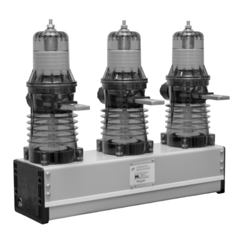
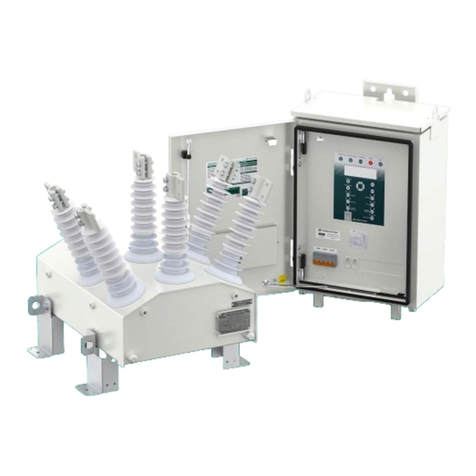
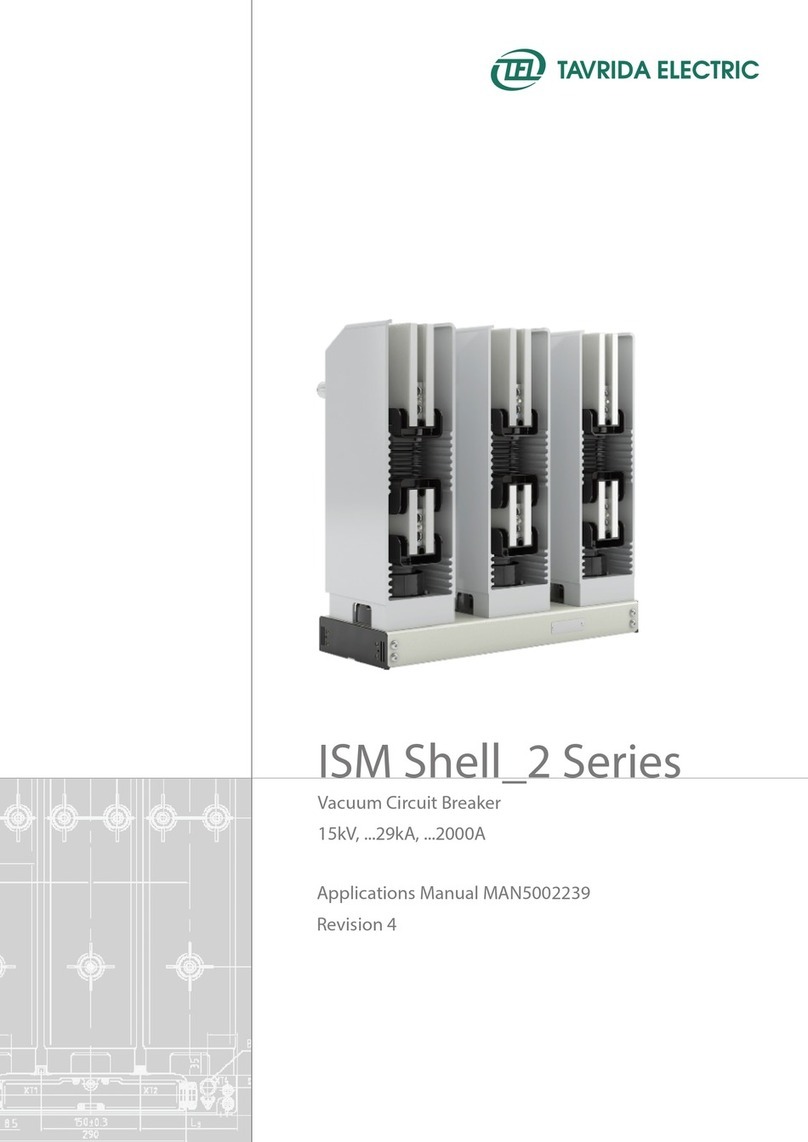
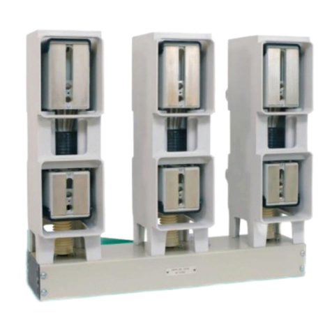
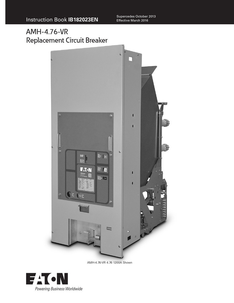
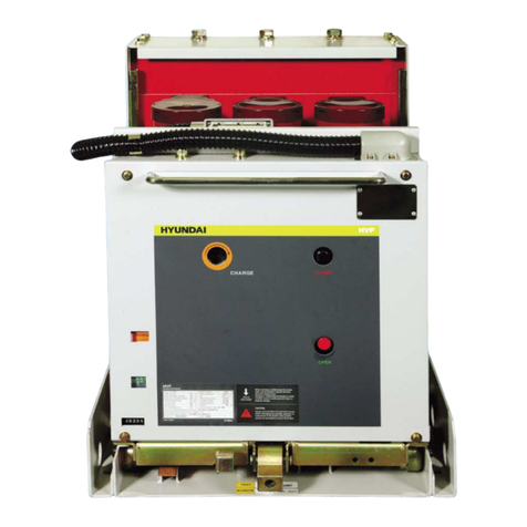
TAVRIDA ELECTRIC VCB15 User manual

WITHDRAWABLE VCB
VACUUM
CIRCUIT
BREAKER
17,5 kV, …31,5 kA, …3150 A
24 kV, …25 kA, …2500 A
PRODUCT GUIDE VERSION 6


Contents
1. Introduction................................................................................................................................................. 5
1.1 Abbreviations .................................................................................................................................... 6
1.2 Denitions......................................................................................................................................... 7
1.3 Disclaimers ........................................................................................................................................ 7
1.4 Precautions........................................................................................................................................ 7
1.5 Warranty ........................................................................................................................................... 8
2. Presentation ................................................................................................................................................ 9
2.1 Product Application Field ................................................................................................................... 10
2.2 Key Benets....................................................................................................................................... 10
2.3 Compliance ....................................................................................................................................... 10
3. Product Coding............................................................................................................................................ 11
3.1 Circuit Breaker Coding....................................................................................................................... 12
3.2 Circuit Breaker Component Coding ................................................................................................... 15
3.2.1 ISM Coding ............................................................................................................................... 15
3.2.2 CM Coding ............................................................................................................................... 16
3.2.3 Auxiliary Plugs Kit Coding.......................................................................................................... 18
3.2.4 Optional Main Circuits Connectors Kit Coding........................................................................... 19
3.2.5 Optional Circuit Breaker Interlock Kit Coding ............................................................................. 20
3.2.6 Optional Kit for Control Module Installation on a DIN Rail.......................................................... 21
3.2.7 Optional Manual Generator Coding........................................................................................... 22
4. Technical Parameters .................................................................................................................................. 23
5. Design and Operation ................................................................................................................................ 33
5.1 Design............................................................................................................................................... 34
5.1.1 Draw-Out Unit........................................................................................................................... 34
5.1.2 Indoor Switching Module .......................................................................................................... 36
5.1.3 Control Module......................................................................................................................... 38
5.2 Operation.......................................................................................................................................... 39
5.2.1 VCB Racking In and Out of the Switchgear ................................................................................ 39
5.2.2 ISM Closing ............................................................................................................................... 40
5.2.3 ISM Opening ............................................................................................................................. 40
5.2.4 ISM Emergency Opening ........................................................................................................... 41
6. Functionality................................................................................................................................................ 43
6.1 Interlocks........................................................................................................................................... 44
6.2 Optional interlocks............................................................................................................................. 45
6.3 Indication .......................................................................................................................................... 45
7. Application Notes ....................................................................................................................................... 49
7.1 Protective Earthing............................................................................................................................. 50
7.2 Primary Connections.......................................................................................................................... 50
7.3 Secondary Equipment........................................................................................................................ 51
7.3.1 VCB Secondary Connections...................................................................................................... 51
7.3.2 CM Secondary Connections....................................................................................................... 54
7.3.3 Auxiliary supply ......................................................................................................................... 55
Appendix 1. Type Tests ................................................................................................................................... 57
Appendix 2. Withdrawable VCB Package Dimensions................................................................................. 61
Appendix 3. Overall Drawings....................................................................................................................... 63
Appendix 4. Secondary Schemes................................................................................................................... 103
List of Changes................................................................................................................................................ 112


1. Introduction

6
This Product Guide describes the withdrawable vacuum circuit breakers manufactured by Tavrida Electric.
Tavrida Electric circuit breakers are designed for rated voltages up to 24 kV.
Withdrawable vacuum circuit breakers are designed for indoor installation in air-insulated switchgear panels and
are intended to perform switching operations in network rated and faulty modes.
The breakers consist of the following main components:
• Indoor Switching Module (ISM) - The air-insulated ISM incorporates Tavrida Electric vacuum interrupters
incorporated in solid dielectric insulator controlled by per phase monostable magnetic actuators. No SF-6 or oil
insulation is used in the ISM.
• Control Module (CM) - The CM is a microprocessor-based controller that provides ISM operation,
protection and data logging functions.
This guide contains information about the circuit breaker‘s technical parameters, functionality and operating
principles. The purpose of the document is to provide necessary product information for application engineers and
technical personnel utilizing the equipment.
Other technical documents which cover the product:
Document name Target audience Purpose of the document
User Guide
Users providing installation,
commissioning and utilizing
installed equipment
Provide information on switching operations, required checkups
and maintenance, as well as service and disposal procedures.
Routine Test Certicate Customer procurement
service Provide information on supplied equipment serial numbers.
1.1 Abbreviations
AC Actuator coil
AS Auxiliary switch
BIL Basic Insulation Level
EMC Electromagnetic compatibility
CM Control Module
CO Close - Open operations cycle
DOU Draw-Out Unit
Com Common point of contact
I/O Input / Output
ISM Indoor Switching Module
LED Light emitting diode
(P)MCB Protective miniature circuit breaker
PS Position switch
NA Not applicable
NC Normally closed contact
NO Normally open contact
PCD Phase center distance
USB Universal Serial Bus
VCB Vacuum Circuit Breaker
VI Vacuum interrupter

7
1.2 Denitions
Closing Time
The closing time is the time period from the moment the close command is applied to the CM to the time when
all ISM poles make contact.
Opening Time
The opening time is the time period from the moment the trip command is applied to the CM to the time when
all ISM poles are separated.
Break Time
The break time is the time period from the moment the trip command is applied to the CM to the time when the
arcs in all phases are extinguished.
1.3 Disclaimers
Tavrida Electric will not accept any claims for damages caused by improper transport, storage as well as unpacking.
Transport damage must be reported in writing to the supplier as soon as it is discovered.
The Product Guide contains information necessary for the installation, commissioning and operation of the with-
drawable vacuum circuit breakers. Please read the Product Guide carefully before starting and to adhere the
instructions and the relevant regulations to ensure the proper use of the withdrawable vacuum circuit breakers.
Tavrida Electric will not accept any claims for damages caused by improper usage of the withdrawable vacuum
circuit breakers. In case of special congurations, please contact Tavrida Electric prior to usage of the withdrawable
vacuum circuit breakers.
1.4 Precautions
• Before selecting the circuit breaker, please check whether the installation place (Contact interfaces, pole centre
and terminal centre distances, xed contact shutters operating mechanism, and the surroundings) is suitable
for the withdrawable vacuum circuit breakers.
• Installation, operation and maintenance shall only be carried out by trained and experienced personnel who
are familiar with the equipment and the electrical safety requirements.
• During installation, commissioning, operation and maintenance of the equipment the relevant legal regulations
(such as DIN/VDE/IEC), accident prevention regulations and the connecting conditions of the electric utilities
shall be followed.
• Take note that during operation of the withdrawable vacuum circuit breakers certain parts are subject to
dangerous voltage. Mechanical parts, also remote-controlled, can move quickly. Failure to comply may result
in death, severe personal injury or damage to equipment.
• Pay attention to the hazard statements located throughout the Product Guide.
• The operating conditions of the withdrawable vacuum circuit breakers shall comply with the technical data
specied in the Product Guide.
• Personnel installing, operating and maintaining the equipment shall be familiar with the Product Guide and
its contents.

8
1.5 Warranty
Unless otherwise stated in the contract, the warranty period is stated in Standard Warranty Policy. If otherwise
agreed to, the contract conditions apply. No warranty is given in the following cases:
a) The warranty period has run out during the period of storage with the customer.
b) The operating conditions, ambient conditions, transport and storage conditions have not been adhered to
according to the application description or the Installation and Operating Instructions.
c) An unauthorized manipulation of the device has been carried out, such as opening the housing or damaging
the seal.
d) The device has not been properly installed, such as incorrect connection of supply voltage of auxiliary circuits.

2. Presentation

10
2.1 Product Application Field
The circuit breaker is usually installed in radial or loop cable or overhead distribution systems. The main
applications are:
• Switching different types of load in normal and fault modes.
• Isolating faults in the cable or overhead network.
Due to their short closing and opening times (see “Technical Parameters” on page 23), Tavrida Electric circuit
breakers can bring signicant benets to the following applications:
• Arc ash protection;
• Automatic backfeed restoration.
2.2 Key Benets
Tavrida Electric circuit breakers provide the following competitive advantages:
• Environmentally friendly
The ISM does not use SF-6 insulation materials.
The CM and ISM modules are manufactured from environmentally friendly materials.
• Lightweight
The total weight of the withdrawable vacuum circuit breakers with a rated current of 1250 A and a CM does
not exceed 88 kg, making it the most lightweight indoor circuit breaker on the market. The total weight of
the withdrawable vacuum circuit breakers with a rated current of 3150 A and a CM does not exceed 165 kg,
making it the most lightweight indoor circuit breaker on the market.
• High reliability
30,000 CO operations at rated current and 50 full rated short-circuit operations without any maintenance
make it the most reliable circuit breaker on the market.
• Fastest operation time
The withdrawable circuit breakers described in this product guide are based on Tavrida Electric ISMs, which
provide extremely fast operation timing and can be successfully utilized for such demanding applications as
fast transfer switch, fast internal arc clearance and other applications.
• High operator safety
The open design of the draw-out unit provides visual control of its main circuit‘s disconnection when it is in
the test position.
In case of auxiliary supply loss, manual charging of the circuit breaker is performed by connecting to the CM
in the low voltage compartment, excluding the necessity of operating inside the high-voltage compartment.
2.3 Compliance
Tavrida Electric withdrawable vacuum circuit breakers have been tested by world-renowned testing laboratories. A
list of test reports is presented in “Appendix 1. Type Tests”.

3. Product Coding

12
VCB15_XX_16D(Par1_..._Par12)
Product group
ISM type
CM and VCB implementation type
3.1 Circuit Breaker Coding
Table 1 - Product Group Description
Code Description
VCB15 Vacuum Circuit Breaker with rated voltage up to 17.5 kV
VCB25 Vacuum Circuit Breaker with rated voltage up to 24 kV
Table 2 - ISM Type Description
Code XX Description
LD8 Three-phase Light duty Indoor Switching Module with rated normal current up to 800 A
MD1 Three-phase Medium duty Indoor switching module with rated normal current up to 1250 A
Shell2 Three-phase Medium duty Indoor switching module with rated normal current up to 2500 A
HD1 Three-phase Heavy duty Indoor switching module with rated normal current up to 3150 A
Table 3 - CM and VCB Implementation Type Description
Code Description
16D The 16th series of Control Module and Draw-Out type VCB
Table 4 - Circuit Breaker Parameters Description
Parameter Parameter description Applicable options Code
Par1 Customization
Default 0 1)
With IP2X front cover without slots 1
Par2 Rated voltage
17.5 kV 17.5 2)
24 kV with 370 mm depth of movable part of cassette 3) 24-1
24 kV with 420 mm depth of movable part of cassette 3) 24-2
Par3 Rated short circuit breaking
current
25 kA 25
31.5 kA 31.5
Par4 Rated normal current
630 A 630
800 A 800
1250 A 1250
2500 A 2500
3150 A 3150

13
1) Please contact your local sales representative for information.
2) 95 kV BIL.
3) The depth of movable part of cassette is shown in the overall drawings in Appendix 3.
4) Not applicable for the VCB with the metal auxiliary plug.
Table 4 - Circuit Breaker Parameters Description
Parameter Parameter description Applicable options Code
Par5 Phase center distance
150 mm 150
210 mm 210
275 mm 275
Par6 Terminal centre distance 205 mm 205
310 mm 310
Par7 Lower terminal height
260 mm 260
280 mm 280
325 mm 325
345 mm 345
Par8 CM settings Basic circuit breaker functionality 1
Without CM NA
Par9 Rated auxiliary supply voltage
24-60 V DC 60
110-220 V AC/DC 220
Without CM NA
Par10 Auxiliary plug Plastic plug 1
Metal plug 3
Par11 Optional interlock
Without optional interlock 0
Electrical interlock preventing DOU racking in/out without
auxiliary voltage -220 V AC/DC 1
Mechanical interlock preventing disconnection of auxiliary
circuits plug with end switch actuator 2 4)
Electrical interlock preventing DOU racking in/out without
auxiliary voltage -220 V AC/DC
AND
Mechanical interlock preventing disconnection of auxiliary
circuits plug with end switch actuator
3 4)
Par12 Language
English EN
Spanish ES
Portuguese PT
Figure 1
VCB electrical data label with serial number
Each VCB has an electrical data label which contains the circuit breaker‘s serial number:

14
The nameplate contains information about the VCB type, the VCB technical parameters and the serial number. The
placement of the electrical data label is shown below.
a) VCB15_LD8_16D labeling b) VCB15_MD1_16D labeling
d) VCB25_Shell2_16D labelingc) VCB15_HD1_16D labeling
Figure 2
Electrical data label placement
ISM electrical data label
ISM electrical data label
ISM electrical data label
ISM electrical data label

15
3.2 Circuit Breaker Component Coding
ISM15_MD_1(Par1_(Par2))
Indoor switching module
Rated voltage
ISM type
The following ISM types are available:
• ISM15_LD_8(Par1_Par2) – Three-phase Light duty Indoor switching module with rated normal current up to
800 A.
• ISM15_MD_1(Par1_Par2) – Medium duty indoor switching module with rated normal current up to 1250 A.
• ISM15_HD_1(Par1) – Heavy duty indoor switching module with rated normal current up to 3150 A.
• ISM25_Shell_2(Par1) – Three-phase medium duty Indoor switching module with rated normal current up to
2500 A
Table 5 - ISM Parameters Description
Parameter Applicable ISM Parameter description Applicable options Code
Par1
ISM15_LD_8
Phase centre distance
150 mm 150
210 mm 210
ISM15_MD_1 150 mm 150
210 mm 210
ISM15_HD_1 210 mm 210
275 mm 275
ISM25_Shell_2 210 mm 210
275 mm 275
Par2
ISM15_LD_8 Design code of ISM Low terminal with two 10 mm holes. The terminal and
interlock outlets have contra directions 1
ISM15_MD_1 Side of position indicator
connection to ISM Left side (between phases A and B) L
3.2.1 ISM Coding
ISM15 – Indoor switching module with rated voltage up to 17.5 kV
ISM25 – Indoor switching module with rated voltage up to 24 kV.
See Table 2 for description of ISM types.

16
CM_16_1(Par1_Par2_Par3_Par4_Par5)
Control module
Control module series
CM type
Table 6 - CM Parameters Description
Parameter Parameter
description Applicable options Code
Par1 Language
English EN
Spanish ES
Portuguese PT
Par2
Rated supply voltage
and CM hardware
version
24-60V DC, version 2 60.2
110-220 V AC/DC, version 2 220.2
Par3 Firmware functionality Basic circuit breaker functionality 1
Par4
ISM driver rmware
used in CM1) and
Protection setting
ISM15_LD_8 and Without protection 15LD8-000
ISM15_MD_1 and Without protection 15MD1-000
ISM15_HD_1 and Without protection 15HD1-000
ISM25_Shell_2 and Without protection 25Shell2-000
Par5 Factory congurable
settings
Relay 1 - Switching module position functionality;
Relay 2 - Ready functionality;
Relay 3 - Malfunction or Loss of auxiliary supply functionality;
Trip by dry contacts close command
Close by dry contacts close command
A.A
Each CM has the following labels:
Figure 3
Serial number label
3.2.2 CM Coding
1) This parameter describes the ISM type(s) that the CM can control. To optimize the operation of each ISM, corresponding settings are used
in the CM rmware. Usage of the CM with the incorrect type of the ISM can lead to a violation of declared VCB parameters.
Figure 4
Label with applicable ISM designation
Figure 5
Warning label
Figure 6
Firmware version label

17
Figure 7
Information label with terminals connections and main parameters
Figure 8
CM labels arrangement
1. Serial number label
2. Label with applicable ISM designation
3. Warning label
4. Firmware version label
5. Information label with terminals connections
and main parameters

18
Table 7 - Circuit Breaker Kit Parameters Description
Parameter Parameter description Applicable options Code
Par1 Auxiliary plug
Plastic plug 1
Metal plug 3
CBkit_Plug_1 is used to provide a counterpart for the DOU auxiliary circuits connector in the switchgear panel.
3.2.3 Auxiliary Plugs Kit Coding
CBkit_Plug_1(Par1)
Circuit breaker kit
Auxiliary plugs kit
Kit type
Figure 9
CBkit_Plug_1(1) scope of supply
Figure 10
CBkit_Plug_1(3) scope of supply

19
The SGkit_Connector_1 is used to provide the switchgear xed contact counterpart for the DOU main circuits
connection.
Figure 11
SGkit_Connector_1(17.5_2000) scope of supply
3.2.4 Optional Main Circuits Connectors Kit Coding
SGkit_Connector_1(Par1_Par2)
Switchgear kit
Main circuits connector kit
Kit type
Table 8 - Switchgear Kit Parameters Description
Parameter Parameter description Applicable options Code
Par1 Rated voltage
≤ 17.5 kV 17.5
≤ 24 kV 24
Par2 Rated normal current
1250 A 1250
2000 A 2000
3150 A 3150
The main circuits connectors kits applicability:
• SGkit_Connector_1(17.5_1250) - for VCB15_LD8_16D, VCB15_MD1_16D;
• SGkit_Connector_1(24_1250) - for VCB25_Shell2_16D;
• SGkit_Connector_1(17.5_2000) - for VCB15_HD1_16D and VCB25_Shell2_16D;
• SGkit_Connector_1(17.5_3150) - for VCB15_HD1_16D.

20
The CBkit_Interlock_6 is used with the DOU to provide it with optional interlock in case this interlock is required
after DOU production. The interlock blocks the DOU rack in/out functionality in case auxiliary voltage (provided for
solenoid installed on DOU plate) is unavailable.
Figure 12
CBkit_Interlock_6(220U)
3.2.5 Optional Circuit Breaker Interlock Kit Coding
CBkit_Interlock_6(Par1)
Circuit breaker kit
Interlock kit
Kit type
Table 9 - Circuit Breaker Kit Parameters Description
Parameter Parameter description Applicable options Code
Par1 Rated supply voltage 220 V AC/DC 220U
This manual suits for next models
1
Table of contents
Other TAVRIDA ELECTRIC Circuit Breaker manuals
