ABB HPA 12kV Guide

MV SF6 Indoor Circuit Breaker
Model HPA 12kV, 24kV & 36kV
1VDU22001-YN
Instruction for Installation, Service and Maintenance

Notice 1
Based on our own experience, you will obtain the best possible operational
reliability from our equipment by following the recommendations given in these
instructions.
The data contained herein purports solely to describe the product and is not a
warranty of performance or characteristics. It is with the best interests of our
customers in mind that we constantly strive to improve our products and keep
them abreast of advances in technology. This may, however, lead to
discrepancies between a product and this instruction.
Notice 2
Within the scope of this instruction, it is impossible to take into account every
possible eventuality which may arise with technical equipment in service. Please
consult our local agents in the event of any irregularities. Especially if not referred
to herein.
Notice 3
We expressly decline liability for any damage resulting from any incorrect
operation or wrong handling of our equipment, even if these instructions contain
no specific indication in this respect. We lay particular stress on the fact that only
genuine spare parts should be used for replacements.
Notice 4
Without our written consent it is not permissible to disclose copy or reproduce any
part of these instructions.

Contents
1.1 Data 03
1.2 Construction & Function 03
1.2.1 Breaker Poles 03
1.2.2 Operating mechanism 06
1.3 Maintenance 10
1.3.1 Maintenance schedule 10
1.3.2 Checking and refilling of SF gas 14
6
1.3.3 Control of gas pressure 15
(Only for poles without pressure gauge)
1.3.4 Checking for operating speed and time 16
1.4 Service instruction 17
1.4.1 Fault finding chart 18
1.4.2 Replacement of operating coils 19
1.4.3 Replacement of micro switch 20
1.4.4 Replacement of auxiliary contacts 21
1.4.5 Replacement of motor 21
1.4.6 Replacement of damping device 21
1.4.7 Replacement of operating mechanism 22
1.4.8 Changing of breaker pole 24
1.4.9 HPA- operating gear adjustments 24
1.5 Accessories Spare parts and additional equipment 25
(2)

HPA - BREAKER
1.1 Data
* Rated voltage kV 12 24 36
* Rated current A 1250, 1600, 1250, 2000, 1250,
2000, 2500, 2500 1600,
3000 2000
* Rated breaking current kA 40 26.3 26.3
* Rated making current (peak) kA 100 66 66
¨Short time rated current, 1/3 sec kA 40 26.3 26.3
¨Sf pressure, (over pressure) bar 2.5 2.5 2.5
6
¨Electrical endurance, (number of
interruptions at rated breaking current) No 6 25 10
¨Mechanical endurance (number of
interruptions at rated current) No 10000 10000 5000
With maintenance as detailed in this manual.
2.2 Construction and function
The circuit breaker type HPA operator on the puffer principle.
2.2.1 Breaker poles
The breaker pole contains Sf gas (sulphur hexafluoride). This gas in many
6
respects is one of the best media for circuit breaker in use for several decades
and its excellent performance is demonstrated by experience.
(3)
Fig - 1
Structure of SF molecule
6

The main characteristics of Sf gas are:
6
¨The gas is neither combustible nor toxic.
¨It is chemically stable and will not age with time.
¨Breaking capacity of Sf6 gas is high even at relatively low pressure, because of
its superior dielectric and thermal properties.
¨The interruption in Sf gas is not forced and thus no over voltages are
6
generated. No damping resistor or surge arrestor is needed, not even when
controlling small motors.
¨The dielectric strength at the relevant pressure is about 3 times higher than air
and is roughly at par with oil.
¨Any leakage is easily detected. To provide an extra margin of safety, the
breaker is capable of interrupting its rated current at rated voltage even at
atmospheric pressure.
The Sf breaker type HPA operates on what is usually referred to as the puffer
6
principle. This involves compressing the gas between a static piston and a movable
cylinder during the interruption action. The compressed gas is then blown through a
nozzle in which the arc is taking place. A combination of careful attention to design
and the use of proven components has meant that arcing times in the new HPA
breaker have been reduced to a minimum. As a result, the new breaker contacts will
normally not need replacement during the service life of the breaker. The breaker pole
operation is shown in fig. 2.
(4)
Fig - 2
(The Puffer Principle)

During the manufacture of the breaker pole, it is dried internally through vacuum
pumping. The breaker pole is then pressurized and also tested against leaks. Inside
the pole there is an absorption medium for the decomposition products of the gas. The
breaker poles should only be opened up by trained service personnel at the
manufacturing factory. The locking screws are tightened up to a predetermined
torque at the factory and must not be opened. If it is assumed that moisture has
entered (gas pressure = atmospheric 0) the pole, the same should be returned to the
factory for repair.
SF gas which has been exposed to arcs contain components which combined with
6
moisture become corrosive. Filling up of gas should always be carried out according
to section 2.3.2 “Checking and Refilling of Sf gas”.
6
(5)
Fig - 3a
(HPA breaker pole for 12 kV / 24 kV)

Fig - 3b
(HPA breaker pole for 36 kV)

1.2.2 Operating mechanism
The operating mechanism has a spring charging device which can be
operated by motor or by hand. Once a closing command has been given it is always
completed by the breaker; this is important in the event of short circuit. Since, the
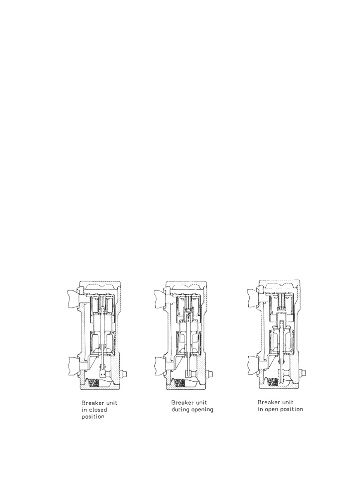
circuit breaker closes completely before it opens, the correct contact speed and full
breaking capacity are obtained. The operating device has compression springs for
closing and opening. The opening spring is charged automatically when the breaker
is closed. A closed breaker with charged closing springs can be operated open - close
- open without intermediate motor or manual charging and the breaker can therefore
be used for auto re-closing. Charging of the closing spring can be discharged by
disconnecting the voltage to the motor and manually operate the breaker close -
open.
An indication shows whether the closing spring are charged or not and the number of
opening operations are recorded on a counter.
The motor can be supplied via a station battery, a network or via a voltage transformer
with a limit load of at least 300 VA. The motor starts after each closing operation and
charges the closing springs within 9 seconds. The breaker is fitted with a knob for
mechanical openings and with magnetic coils for closing and openings. The same
operating mechanism is used for all types of HPAbreaker.
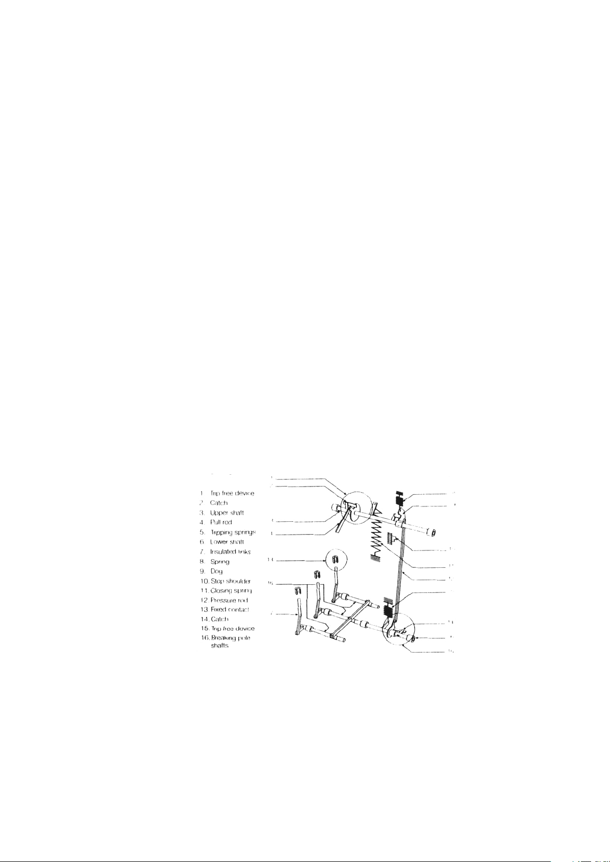
The construction of the operating mechanism is shown in fig. 4. The device has two
shafts. The lower shaft (6) is connected to the breaker poles via links and is directly
actuated by the openings springs (5). The upper shaft (3) is connected directly to the
closing spring (11). These two shafts are linked via the driving disc (9) and the link
(12), and by the trip free device (14). The upper shaft is also connected to the charging
device via the trip-free device (1) and the link (4).
The latching and trip-free devices (1) and (14) are of the same type that have been
used inABB equipment since 1950 and have proven extremely reliable.
The motor operated unit consists of a toothed transmission gear with an eccentrically
driven tooth wheel as a last step. The operating device also contains auxiliary
contacts and trip coils.
(6)
Fig - 4
(Principle diagram of Circuit Breaker)

(7)
Fig - 5
(Circuit Breaker)

SPRING MECHANISM
SR. NO. ITEM DESCRIPTION PART NO.
1 & 2 Trip free device top IN 5436 0001 -A
3 Upper shaft assembly IN 5439 0002 - D
4 Link or pull rod IN 2104 00101 -AK
5 Opening spring IN 2192 0002 - D
6 Bottom shaft assembly IN 5439 0002 - B
7 Insulating links will not be supplied loose
8 Spring IN 2192 0001 - 21
9 Driver IN 2184 0002 - 34
10 A) Stopper or M16 X 50
Hex socket head
Grub screw IN 2122 2768 - 50
B) M16 nut IN 2126 2768 - 124
C) M16 spring washer IN 2154 2022 - 9
11 Closing spring IN 2192 0002 - B
12 Link IN 2194 0001 -AE
13 Contact will not be supplied loose
14 & 15 Trip free device (bottom) IN 5436 0001 - B
OPERATING MECHANISM
SR. NO. ITEM DESCRIPTION PART NO.
1 Closing coil IN 5274 0001 -A*
2 Closing Damping device IN 5256 0711 - 4
3 Micro switch IN 5445 0744 -A
4 Fixing bolts for
Operating device tripping coil IN 5274 0001 -A*
5 Short cover IN 5428 0002 - 2@
6 ‘O’ ring IN 2152 2018 - 10@
7 Density switch IN 5663 0162 - 1
8 Auxiliary contact IN 5218 0004 - 1
9 Motor IN 4461 0002 - E*
10 Indicating plate assly. IN 5428 0001 - M
11 Counter IN 5692 0501 - 2
*Please specify voltage.
@ If density Switch is used, short cover will be supplied in place of refilling vent
(8)

(9)
Operating Mechanism Working Principle:
Fig. 6A shows the operating device with
the breaker in the open position. The
closing spring (11) is charged if the latch
(2) is tripped, the upper shaft is released,
its turning is transmitted via link (12) to
the breaker pole shafts (6).
In fig. 6B the breaker has closed and at
the same time the opening spring (5) has
been charged. Driving disc (9) comes to
rest against stop (10) which, via link (12)
and trip free device (14) also prevents the
opening spring turning the breaker pole
shaft (6). Now the charging device starts
and link (4) moves upwards until latch (2)
is engaged. At this point link (4) turns and
begins to move downwards, whereupon
the upper shaft turns and retentions. The
closing spring position is reached
according to fig. 6C.
During the breaker opening, latch (14) is
released, thus releasing the lower shaft
which via the insulating links (7), actuates
the moving contact of the breaker poles,
for interruption. The spring (8) returns the
link (12) with the associated driving pin
and the operating device to the position in
fig. 6A.
For rapid re-closing the associated
switchgear cubicles can be fitted with
suitable relay equipment. The HPA can
be fitted with two opening coils, one
closing coils.
Fig - 6A
Fig - 6B
Fig - 6C

2.3 Maintenance
2.3.1 Maintenance schedule (As per Drg. 1VYN400290-005 Pg. 11 & 12)
Sr. Description Before Interval Interval Every
No. Start up of 6 months of 5 years 1000 operation
01 CHECKING OF OPERATING
MECHANISM.
1.1 Checking of fastener tightness fig. 7A
Item B. H. L. & M. aa---- a
1.2 Checking of shock absorbers for
Leakage or stuck-up fig. 7A item F & G aa---- a
1.3 Checking of top & bottom trip free
mechanism, cap & coupling
Fig. 7A, item J & K aa---- a
1.4 Closing & Tripping spring assembly
& split pin (N) on them (fig. 7A) ---- ---- ---- a
1.5 Bearing item (P) fig. 7A ---- ---- ---- a
1.6 Checking of setting
*Coupling and knife catch gap
(Setting 1, fig. 7B)
*Bottom TFM and CAP gap
(Setting 2, fig. 7A) both gaps should
be between 1 - 2 mm aa---- a
1.7 Spring cut off micro switches. aa---- a
02 OVERHAUL & LUBRICATION OF
CHARGING DEVICE AND
OPERATING GEAR ---- ---- a----
03 GAS PRESSURE CHECK aaaa
NOTE
1) Complete overhaul of circuit breaker with replacement of poles to be done after 10,000 operations.
2) Ask ABB for details of overhaul procedures.
(10)

Fig. 7A
Maintenance schedule for frequently operated breaker type HPA (1VYN400290-005)
(11)

Fig. 7B
Maintenance schedule for frequently operated breaker type HPA (1VYN400290-005)
(12)

Electrical endurance (HPA)
(13)

1.3.2 Checking and Refilling of SF Gas
6
Checking and refilling can be done with the front plate fixed. Refilling not be carried
out with the breaker in service position. The gas pressure should be between 3 and
0
3.5 bar absolute, in other words 2 and 2.5 bar over pressure at 20 C. Lower currents
than 25kA can still be in broken at lower pressure. Rated current can be interrupters at
atmospheric pressure provided that there is SF gas in the breaker pole, which is
6
certainly valid if there is little over pressure.
0
At temperature other than 20 C of the gas the pressure (abs.) must be according to
the table below.
Pressure at Corresponding pressure in bars at various temperatures
0
20 C abs.
0 0000
Bar 0 C 10 C 20 C 30 C 40 C
0.5 0.47 0.48 0.50 0.52 0.54
1.0 0.93 0.97 1.00 1.03 1.06
1.5 1.40 1.45 1.50 1.55 1.60
2.0 1.36 1.93 2.00 2.07 2.14
2.5 2.33 2.41 2.50 2.59 2.68
3.0 2.80 2.90 3.00 3.10 3.20
3.5 3.26 3.42 3.50 3.62 3.74
The HPA breaker can be fitted with a density gauge with an alarm contact and
indicator. The green area of the indicator shows the correct pressure, the yellow area
indicates enough pressure for breaking, and when the indicator shows red the pole
has to be refilled with SF gas. If the breaker is not supplied with density gauge the
6
pressure is measured manually with a special instrument. The measurements should
take place at three intervals. The HPA circuit breaker can also be fitted with pressure
switches.
Checking and refilling of SF gas is carried out according to the following instruction.
6
Equipment according to fig. 16 is needed.
(14)
Fig - 8
Connection for filling of Breaker with SF gas
6

SF GAS REFILLING EQUIPMENT
6
Sr. No. ITEM DESCRIPTION PART No.
1 Gas cylinder S 194-5600-103-17 supplied in 10 kg or 25 kg
cylinder.
2 Regulator
a) cylinder pressure gauge
b) outlet pressure gauge
c) reducing valve IN 6821 0001 - 1
3 Pressure House IN 2515 0001 - 1
4 Gas filling valve ‘OR’ Snap connection IN 2529 0001 - 7
5 Connecting nipple IN 2529 0001 - 8
IN 2529 0001 - 9
IN 2529 0001 - 5
6 Refilling unit with density switch IN 5428 0001 - 5
without density switch IN 5428 0001 - 6
with pressure switch 1VYN 400 201 - AY
1.3.3 Control of gas pressure (only for poles without pressure gauge / Pressure switch)
1. Close metering pressure valve
2. Connect metering pressure gauge to pole.
3. Read pressure compensation for temperature as shown on page 14. If reading
Is between 2.0 and 2.5 disconnect gauge.
4. Disconnect the operating device by disconnecting the voltage to the motor
and operate by hand “close” and “open”.
5. Close cylinder reducer valve.
6. Close charging valve.
7. Open cylinder main valve, and note reading on gauge (should show approx.
70 bar for full cylinder).
8. Open the reducer valve until a reading of 2.5 bar pressure is registered.
(If the reading is too high, close reducer valve and release gas by opening
charging valve with hose disconnected).
9. Open charging valve a little so that the gas leaks a little, thereby emptying
Hose of any air.
10. With the use of the snap connection, connect the hose to the metering tube.
11. Open the metering pressure valve.
(15)

0
12. Open the charging valve until a reading of 2.5 bar (20 C) is registered on the
metering gauge.
13. Close cylinder main valve.
14. Close both charging and metering valves.
15. Loosen the snap connection.
Note: The hose contains gas at a pressure of 2.5 bar and this will blow out.
16. Loosen the metering unit until gas begins to escape, then disconnect
immediately the metering unit so that the back pressure valve in the pole
automatically closes.
17. Disconnect metering unit.
18. Check the O-ring of the covers, if they are dry, exchange with new ones
which have been greased withABB grease IN 1171 4014 - 49.
Note: Mineral grease must not be used on EPDMO - rings. Replace the cover
on the connection nipple.
1.3.4 Checking of operating speed and time
Checking of operating speed can be made with a capacitive sensor. The
sensor is connected to a conventional oscilloscope. The curve shown in fig. 9 shows
what valves should be obtained on the oscilloscope.
Closing speed (a/10) 2.0 - 2.5 mtrs. / sec.
Opening speed (b/10) 3.6 - 4.3 mtrs. / sec.
Closing time with nominal voltage max. 75 ms
Opening time with nominal voltage 36 - 45 ms
Contact travel 62 - 66 mm
(16)
Fig - 9
(Travel diagram)

Functional check is carried out as follows
1. Connect the sensor to the connecting link of the poles, see fig. 10.
2. Check with the aid of vernier callipers that the movement from open to closed
positions is 81 - 85 mm.
3.Adjust the oscilloscopes input to 85 mm, see fig. 9.
4. Make an opening operation. The curve on the oscilloscope should be as shown in
fig. 9.
5. Make a closing operation.
6. If the speeds are not correct, the spring force is to be adjusted. See section 1.4.9
“Adjustment of operating device”.
1.4 Service instructions
Safety instructions - For dismantling and servicing of breakers, the following
steps should be followed:
1. Disconnect the breaker.
2. Pull out the breaker on the door.
3. Manually release the closing springs.
4. Manually release the opening springs.
(17)
Fig - 10
(Connection of capacitive sensor)

1.4.1 Fault finding chart
FAULT CAUSE REMEDY
Spring will not charge Motor has wrong or no Measure voltage on the
operating voltage motor leads.
Motor shaft broken Change motor
Motor gear damage Change motor
The latch for tripping Check mechanism
device does not function NOTE: Read safety
instruction in paragraph
1.3 before taking action
Disconnection in the wires Check by measuring.
Closing of breaker does not Operating coil does not pull Measure the voltage,
take place although there adjust the coils adjust-
is an indication that the ment screw.
springs are tensioned. Check breaker springs
Breaker closes then opens The toggle joint of the Adjust the toggle joint
again. mechanism are incorrectly
adjusted
Main circuit is wrong Find fault and adjust
Wrongly adjusted
clearance of opening Adjust
magnets armature
Breaker continuously opens Anti-pumping relay wrong Change relay
and closes
Breaker will not close Micro-switch arm wrongly Find fault and adjust
completely adjusted
Under-voltage relay Find fault and adjust
released.
(18)
This manual suits for next models
2
Table of contents
Other ABB Circuit Breaker manuals

ABB
ABB SACE Emax 2 User manual

ABB
ABB Emax User manual

ABB
ABB SACE Emax 2 User manual

ABB
ABB S 280 UC Series Instruction manual

ABB
ABB Emax Use and care manual

ABB
ABB F200 B Service manual

ABB
ABB SACE Emax 2 User manual

ABB
ABB Mechanism HMB-8 User manual

ABB
ABB XT7M User manual

ABB
ABB SACE Tmax T4 User manual

ABB
ABB Emax X1 B/E 1150 V User manual

ABB
ABB F204 125 Series User manual

ABB
ABB SF6 LTB 245E1 BLG 1002A User manual

ABB
ABB SACE Emax 2 Manual

ABB
ABB SACE Emax 2 User manual

ABB
ABB ADVAC 38 User manual

ABB
ABB Emax 2 Retrofill AKR-30-800A Product manual

ABB
ABB SACE Emax 2 - Tmax XT User manual

ABB
ABB SACE Emax Series Manual

ABB
ABB FH200A User manual