TAVRIDA ELECTRIC Rec15 User manual

The present Technical Manual contains information necessary for the installation, commissioning and
operation. It is absolutely necessary for the proper use of the recloser to read the Technical Manual carefully
before starting and to adhere to the instructions and the relevant regulations.
Safety first
•Installation, operation and maintenance shall only be carried out by trained and experienced personnel who
are familiar with the equipment and the electrical safety requirements.
•During installation, commissioning, operation and maintenance of the equipment the relevant legal
regulations (such as IEC/DIN/VDE), accident prevention regulations and the connecting conditions of the
electric utilities shall be followed.
•Take note that during operation of the recloser certain parts are subject to dangerous voltage. Mechanical
parts, also remote-controlled, can move quickly. Failure to comply may result in death, severe personal
injury or damage to equipment.
•Pay attention to the hazard statements located throughout this manual.
•The operating conditions of the recloser shall comply with the technical data specified in this manual.
•Personnel installing, operating and maintaining the equipment shall be familiar with this manual and its
contents.
For special configurations please contact Tavrida Electric representative.

3
Contents
1Introduction....................................................................................................................................................5
1.1 Applicability ..............................................................................................................................................6
1.2 Safety Instructions:...................................................................................................................................6
1.3 Abbreviations............................................................................................................................................7
2Technical Parameters....................................................................................................................................9
3Product Description.....................................................................................................................................14
3.1 Outdoor Switching Module.....................................................................................................................15
3.2 Control Cable .........................................................................................................................................17
3.3 Recloser Control.....................................................................................................................................17
4Functionality.................................................................................................................................................27
4.1 Protection...............................................................................................................................................28
4.2 Measurement .........................................................................................................................................50
4.3 Communication ......................................................................................................................................52
4.4 Remote Engineering...............................................................................................................................53
4.5 Indication................................................................................................................................................54
5Product Handling.........................................................................................................................................56
5.1 Transportation........................................................................................................................................57
5.2 Storage Conditions.................................................................................................................................58
5.3 Inspection...............................................................................................................................................58
5.4 Unpacking ..............................................................................................................................................58
5.5 Handling Requirements..........................................................................................................................62
6Installation....................................................................................................................................................69
6.1 Required Equipment...............................................................................................................................70
6.2 Installation Procedure.............................................................................................................................70
6.3 Dismounting Procedure..........................................................................................................................80
4
7Commissioning............................................................................................................................................81
7.1 No-load Tests.........................................................................................................................................82
7.2 On-load Tests.........................................................................................................................................83
8Operation......................................................................................................................................................84
8.1 Switching................................................................................................................................................85
8.2 Logging...................................................................................................................................................86
8.3 Measurements........................................................................................................................................88
8.4 Date and Time Settings..........................................................................................................................88
8.5 Other RC5_4 Control Options................................................................................................................88
8.6 Settings Configuration............................................................................................................................95
9Maintenance and Troubleshooting..........................................................................................................100
9.1 Maintenance.........................................................................................................................................101
9.2 Troubleshooting....................................................................................................................................101
9.3 Components Replacement Procedure.................................................................................................109
10 Product Coding..........................................................................................................................................115
10.1Recloser Coding...................................................................................................................................116
10.2Recloser Components Coding.............................................................................................................119
11 Appendices.................................................................................................................................................122
Appendix 1. Type Tests...............................................................................................................................123
Appendix 2. Spare Parts and Accessories ..................................................................................................125
Appendix 3. Outdoor Switching Module Drawings.......................................................................................126
Appendix 4. Recloser Control Drawings......................................................................................................128
Appendix 5. Control Cable Drawings...........................................................................................................129
Appendix 6. Package Drawings...................................................................................................................130
Appendix 7. Mounting Kits Drawings...........................................................................................................132
Appendix 8. Connectors Drawings ..............................................................................................................163
Appendix 9. Recloser Control Wiring Diagram............................................................................................170
List of changes.............................................................................................................................................171

1 Introduction

6
1.1 Applicability
This Technical Manual applies to the following range of products manufactured by Tavrida Electric:
•Automatic Circuit Recloser –Rec15/25_Al1_5p
▪Outdoor Switching Module –OSM15/25_Al_1
▪Recloser Control –RC5_4
The model numbers are shown on the equipment nameplates. If your equipment does not correspond to these
numbers then this Technical Manual is not applicable.
Every care has been taken in the preparation of this manual. However, please note that not all the details or
variations in the equipment or process being described can be covered. Neither is it expected to address all
contingencies associated with the installation and operation of this equipment. For any further information
please contact your nearest Tavrida Electric representative.
Important! Due to continuous product improvement, specifications and design are subject to change
without notice.
1.2 Safety Instructions:
General hazard statements applicable to this equipment are described in this section. Statements related to
specific tasks or procedures are located throughout this manual.
DANGER! Contact with hazardous voltage can cause death or severe personal injury. Contact with switching
module or recloser control terminals should only be undertaken when equipment is isolated from applicable
sources of voltage.
WARNING! Follow all locally approved safety procedures when installing or operating this equipment.
Improper handling, installation, operation or maintenance can result in death, severe personal injury or damage
to equipment.
WARNING! Power distribution equipment must be properly selected and used only for the intended purpose.

7
1.3 Abbreviations
ABR
Automatic Backfeed Restoration
AT
Auxiliary Transformer
BAT
Battery
BF
Bolted Fault
BTM
Bluetooth Module
CC
Control Cable (Umbilical)
CCV
Close condition verifier
CLP
Cold Load Pickup
CPM
Control Panel Module
CT
Current Transformer
CU
Current unbalance
D
Delayed
EF
Earth Fault protection element
EF1
Low set Earth Fault protection element for Delayed trips
EF2
Low set Earth Fault protection element for Instantaneous trips
EF3
High set Earth Fault protection element for Instantaneous trips
EFID
Earth Fault Interruption Detection
EL
Event Log
ETH
Ethernet Module
HL
Hot Line protection element
I
Instantaneous
I/O
Input/Output
IOI
Input/Output Interface
IOM
Input/Output Module
LCD
Liquid Crystal Display
LP
Load Profile
LS
Loss of Supply protection element
ME
Measurement element
ML
Malfunction Log
MMI
Man Machine Interface
MPM
Main Processor Module
NAP
Neutral Admittance Protection
NVS
Neutral Voltage Shift
OC
Overcurrent protection element
OC1
Low set Overcurrent protection element for Delayed trips
OC2
Low set Overcurrent protection element for Instantaneous trips
OC3
High set Overcurrent protection element for Instantaneous trips
OCID
Overcurrent Interruption Detection
OCR
Overcurrent protection element with reclosing
PCI
Personal Computer Interface

8
PSFM
Power Supply Filter Module
RC
Recloser Control
RCM
Recloser Control Module
RTC
Real Time Clock
RTU
Remote Telecommunication Unit
SA
Surge Arrester
SCADA
Supervisory Control And Data Acquisition
SD
Source Detector
SECR
Sectionalizer Reclosing
SEF
Sensitive Earth Fault
SEFID
Sensitive Earth Fault Interruption Detection
SEFR
Sensitive Earth Fault with reclosing
SI
Synchronization indicator
TCI
Telecommunication Interface
TDI
TELARM Dispatcher Interface
TEL
Tavrida Electric
UF
Under Frequency
UV
Under Voltage
VRC
Voltage Reclosing Control
VT
Voltage Transformer
VU
Voltage Unbalance
ZSC
Zone Sequence Coordination

2 Technical Parameters

10
Main technical data and recloser technical parameters are presented in tables below.
Table 1 –Recloser technical parameters
Parameter
OSM15_Al_1
OSM25_Al_1
Rated data
Rated maximum voltage (Ur)
15.5 kV
27 kV
Rated short-duration powerfrequency withstand voltage (Ud), 1 min dry
50 kV
60 kV
Rated short-duration powerfrequency withstand voltage, 10s wet
45 kV
50 kV
Rated lightning impulse withstand voltage (peak) (Up)
110 kV
1251/ 1502kV
Rated continuous current (Ir)
630 A
630 A
Rated cable-charging current switching
10 A
25 A
Rated line-charging current switching
2 A
5 A
Rated short-circuit breaking current (Isc)
16 kA
12.5 kA
Rated peak withstand current (Ip)
41.6 kA
32.5 kA
Rated short-time withstand current (Ik)
16 kA
12.5 kA
Rated duration of short circuit (tk)
4 s
4 s
Rated frequency (fr)
50/60 Hz
50/60 Hz
Switching performance
Mechanical life (CO-cycles)
30 000
30 000
Operating cycles, rated current (CO-cycles)
30 000
30 000
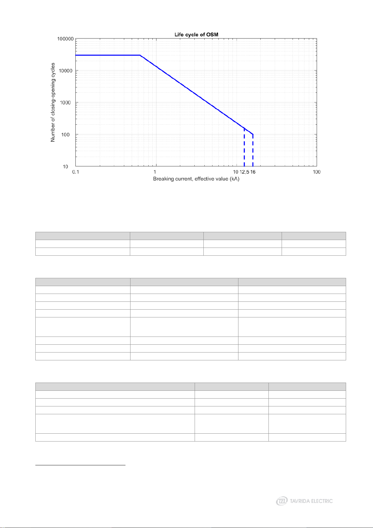
Electrical endurance, breaking current (O-CO cycles)
See Figure 1
See Figure 1
Closing time, not more than
77 ms
77 ms
Opening time for overcurrent protection according to IEC 62271-111/C37.60, not
more than (at I>2xIp)
43 ms
43 ms
Clearing time for overcurrent protection according to IEC 62271-111/C37.60, not
more than (at I>2xIp)
51 ms
51 ms
Rated operating sequence
O-0.1s-CO-2s-CO-2s-CO
O-0.1s-CO-2s-CO-2s-CO
General information
Main circuit resistance
< 85 μOhm
< 95 μOhm
Weight
68 kg
72 kg
Altitude
2000 m (derating according
to ANSI C37.60 applied
above 1000 m)
2000 m (derating
according to ANSI C37.60
applied above 1000 m)
Humidity
100%, condensing
100%, condensing
Solar Radiation
≤ 1.1 kW/m²
≤ 1.1 kW/m²
Temperature Range
-40 °C ... +55 °C
-40 °C ... +55 °C
Type of driving mechanism
Monostable magnetic
actuator
Monostable magnetic
actuator
Pollution level
Very heavy (as per IEC
60815)
Very heavy (as per IEC
60815)
1
Across vacuum gap
2
Closed contacts
11
Figure 1
Vacuum interrupter switching life cycle
Table 2 –Sensors parameters
Parameter
Phase current sensors
Zero-sequence current sensor
Voltage sensors
Range where accuracy is provided
1 … 80003A
1 … 80003A
0.3 … 27 kV
Range of sensor coefficients at 20°C
1.8 … 2.2 V/kA
1.8 … 2.2 V/kA
0.1 … 0.2 V/kV
Table 3 –Measurement accuracy
4
Parameter
Basic error
Range where accuracy is guaranteed
Phase currents
The greater of ±1% or ±2A
0 ... 630 A
Residual current5
The greater of ±5% or ±0.5A
0 ... 400 A
Phase to earth voltages
The greater of ±1% or ±0.1 kV
0.3 ... 16.0 kV
Line to line voltages
The greater of ±1% or ±0.1 kV
0.5 ... 27.0 kV
Frequency
- at dF/dt<0.2 Hz/s
- at dF/dt<0.5 Hz/s
±0.025 Hz
±0.05 Hz
45 ... 55 Hz, 55 ...65 Hz
Power factor
±0.02
0 ... 1
Active and reactive energy
±2%
40 … 630A, 4.5 ... 27 kV
Active, reactive and total power
±2%
40 … 630A, 4.5 ... 27 kV
Table 4 –Electromagnetic compatibility
Parameter
Rated value
Applicable standard
Rated power frequency voltage (1 min)
2 kV
IEC 60255-5
Rated impulse voltage, at 0.5J
5 kV
IEC 60255-5
Electrical fast transient/burst immunity
4 kV
IEC 60255-22-4 (Level IV)
Surge immunity (applied to external AC voltage terminals)
- common
- transverse
4 kV
2 kV
IEC 61000-4-5 (Level IV)
Control elements surge withstand capability (SWC)
125 kV (6 kA)
IEEE C37.60-2012
3
The Rogowski coil can measure current in a wide range but for the purpose of over-voltage, protection suppressors are fitted in the secondary circuits. These
suppressors chop the signal from the Rogowski coil if primary current exceeds 8 kA.
4
If RC5_4 sensor coefficient settings are configured in accordance with guidelines in Table 6 of this guide. Error is measured at normal climatic conditions.
5
Note that overcurrent protection pickup setting value shall not exceed SEF pickup setting value times 300.

12
Table 5 –Power supply characteristics
Parameter
Value
Supply voltage range
85 … 265 V AC
110 … 220 V DC6
Rated power consumption, not more
40 VA
Maximum power consumption, not more
75 VA
Duration of operation without auxiliary supply
48 hours
Table 6 –Degree of protection
Component
Degree of protection
Outdoor switching module
IP65
Recloser control
IP65
Control cable
IP65
Table 7 –Rechargeable Battery (BAT) parameters
Parameter
Value
Type7
G26EPX EnerSys 0765-2003 sealed
lead acid
HAZE HZB12-26 sealed lead acid
Rated voltage
12 V
12 V
Rated capacity
26 Ah
26 Ah
Temperature range
-40 °C ... +55 °C
-25 °C ... +50 °C
Relative capacity at different temperatures
25 % at -40 °C
65 % at -20 °C
84 % at 0 °C
100 % at +25 °C
110 % at +40 °C
120 % at +55 °C
50 % at -25 °C
65 % at -15 °C
85 % at 0 °C
100 % at +20 °C
102 % at +40 °C
Expected battery life at average operating temperature
16 years at +20 °C
10 years at +25 °C
6.5 years at +30 °C
2.7 years at +40 °C
12 years at +20 °C
9 years at +30 °C
4 years at +40 °C
0.8 years at +50 °C
Table 8 –Input/Output module (IOM) parameters
Parameter
Value
Digital inputs
Rated voltages of signal applied to digital inputs
- for IOM-04
- for IOM-03
12/24/30/48/60 V DC
110/125/220 V DC
Pickup voltage of signal applied to digital inputs
- for IOM-04
- for IOM-03
Above 7 V
Above 100 V
Reset voltage
- for IOM-04
- for IOM-03
Below 3 V
Below 30 V
Maximum continuous voltage of signal applied to digital inputs
- for IOM-04
- for IOM-03
75 V
275 V
Input resistance
- for IOM-04
- for IOM-03
3 kOhm
125 kOhm
Recognition time, not more
20 ms
Reset time, not more
20 ms
Digital outputs
Rated voltage
250 V AC
Rated current
16 A
Breaking capacity DC1 (at L/R=1ms): 30/110/220 V
16/0.3/0.12 A
Minimum switching load
500 mW (10V/5mA)
6
Note that additional DC circuit breakers are required.
7
Other types of batteries with identical parameters can be used in RC5_4 upon agreement with client.

13
Table 9 –Wired Ethernet module (ETH) parameters
Parameter
Value
Applicable standard
USB 1.2 (according to RC5 specification)
IEEE 802.3 10Base-T
IEEE 802.3u 100Base-T
IEEE 802.3x Flow Control
Interface
RJ-45 10/100 Ethernet port
Maximum receive / transmit speed
Up to 70 Mbps (full duplex mode)
Dimensions
60.2 x 50 x 37.6 mm
Net weight, not more
25 g
Power consumption
1.0 W (max)
Operation temperature
-40…+85 °C
Table 10 –Optical Ethernet module (ETH) parameters
Parameter
Value
Applicable standard
USB 1.2 (according to RC5 specification)
IEE802.3u 100Base-FX
IEC 9314-3: 1990
ANSI X3.166-1990
Interface
ST
Maximum receive / transmit speed
100–125 Mbps (full duplex mode)
Dimensions
132 x 71 x 39 mm
Net weight, not more
115 g
Power consumption
1.0 W (max)
Operation temperature
-40…+85 °C
Table 11 –Bluetooth module (BTM) parameters
Parameter
Value
Bluetooth version
2.0
Frequency
2402 … 2485 MHz
Channel intervals
1 MHz
Operation range
10 m
Operation mode
Slave
Profile
Serial port
Tx Power
+6 dBm
Rx Sensitivity
-84 dBm
Power consumption
0.3 W
Operation temperature
-40…+85 °C
Table 12 –Wi-Fi module (WFM) parameters
Parameter
Value
Applicable standard
FCC/CE/TELEC/SRRC
Protocol
802.11b, 802.11g, 802.11n, 802.11e, 802.11i
TCP/IP
DHCP
Tx Power
802.11b: +20 dBm
802.11g: +17 dBm
802.11n: +14 dBm
Rx Sensitivity
802.11b: -91 dBm (11 Mbit/s)
802.11g: -75 dBm (54 Mbit/s)
802.11n: -72 dBm (MCS7)
Security
WPA/WPA2
Cipher Type
WEP/TKIP/AES
Power consumption (Pout = +17 dBm)
1.0 W
Operation range
50 m
Operation temperature
-40…+85 °C

3 Product Description
15
3.1 Outdoor Switching Module
The OSM15/25_Al_1 is a three-phase vacuum circuit breaker designed for outdoor application with the rated
maximum voltage of 15.5 kV and 27 kV correspondingly.
The circuit breaker is installed inside of a lightweight aluminum enclosure with a superior corrosion protection
and very heavy pollution areas application rating. The enclosure of the Outdoor Switching Module
encapsulates a magnetic actuator, mechanical trip and lockout mechanism and auxiliary electric circuits that
contain passive electronic components only.
The switching module is equipped with six high voltage bushings with embedded current and voltage sensors.
The bushings are covered by silicone rubber insulation and mount on the top of the tank and provide 500 mm
(OSM15) or 860 mm (OSM25) creepage distance.
The bushings are marked with the terminal designation X1, X2 or X3 for the default source side and X4, X5 or
X6 for the default load side. The source and load side can be reversed in the RC settings if required.
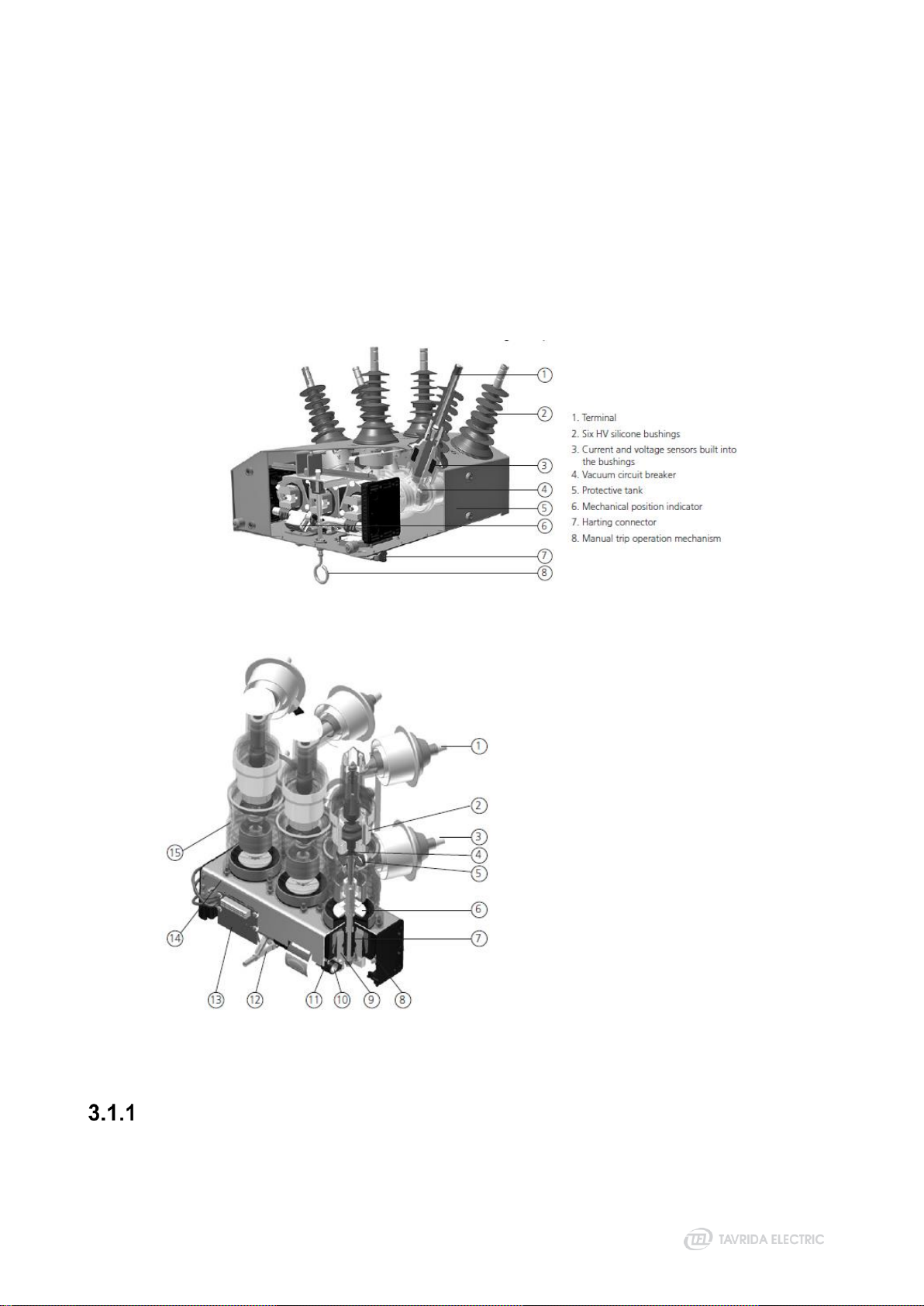
Figure 2
General arrangement of the OSM15/25_Al_1
Figure 3
Internal arrangement of the OSM15/25_Al_1 vacuum circuit breaker
1 Upper terminal
2 Vacuum interrupter
3 Lower terminal
4 Movable contact with bellows
5 Flexible junction shunt
6 Drive insulator
7 Opening and contact pressure spring
8 Magnetic actuator (complete module)
9 Armature
10 Synchronizing shaft
11 Actuator coil
12 Interlocking pins
13 Auxiliary contacts
14 Frame
15 Support insulator
Mechanism Enclosure
The switching module mechanism enclosure is made of a corrosion resistant anodized aluminum alloy. The
enclosure is coated with light gray powder coating.
16
Fixing holes (M12) on each side of the enclosure allow the application of various mounting kits and installation
on poles and other structures.
The earthing provision (M12) is labelled for identification.
Magnetic Actuator
Tavrida Electric has the most reliable mechanical structure of the vacuum circuit breaker. It uses single-coil
magnetic actuators. All switching elements of a pole are assembled along a single axis. All mechanical
movements are therefore direct and linear. Design of the magnetic actuator guarantee minimum contacts
discrepancy at closing and electrical or mechanical tripping.
Due to the design, any typical failures of critical components, such as mechanical latching, gears, chains,
bearings and levers, tripping and closing coils, motors to charge springs are completely avoided.
Vacuum Interrupter
Tavrida Electric vacuum interrupters are the most compact in its class and show excellent mechanical, voltage
withstand and current breaking capabilities. The use of a specially designed axial magnetic field distribution
provides even current density over the contact surface and consequently substantial improvement of vacuum
interrupting performance. Advanced technology and materials provide vacuum integrity in vacuum interrupter
during the entire switching module lifetime (30 years).
Current and Voltage Sensing
Current sensing is performed by low power current sensors (Rogowski coils) that are inbuilt into each pole. It
ensures a precise acquisition of both phase and neutral currents at a very wide range without saturation.
Six precise low power capacitive voltage sensors on source and load side terminals are inbuilt into poles. It
allows the recloser to provide power quality monitoring and network self-healing algorithms implementation.
For details on sensor parameters refer to “Technical Parameters” section of this guide.
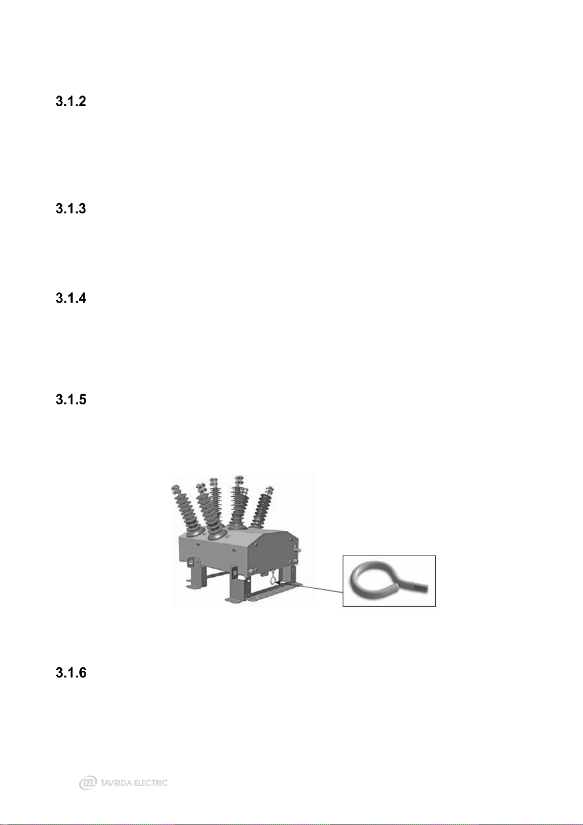
Mechanical Trip and Lockout Mechanism
A mechanical trip hook is located at the bottom of the mechanism enclosure (Figure 3). When the hook is
pulled down, the Outdoor Switching Module is mechanically opened, locked in the OPEN position and
electrically isolated from the driver. The “Coil Isolated” warning event is generated by the RC5_4 to provide
indication of the locked state. The Outdoor Switching Module remains locked and cannot be operated until the
trip hook is pushed back into the operating position.
Figure 4
Mechanical trip hook
Main Contact Position Indicator
The position indicators are located under a protective cover at the bottom of the mechanism enclosure and is
clearly visible from the ground. The indicator color is red “I”when the main contacts are closed and green “O”
when they are open.

17
Figure 5
Main contact position indicator
3.2 Control Cable
Umbilical_5 control cable connects the Outdoor Switching Module actuator, metering and auxiliary circuits to
the RC5_4. Control cable wires are well protected from UV radiation and sharp objects. The cable is equipped
with a heavy duty 42 pin male connectoron the Outdoor Switching Moduleside and a heavy duty 32 pin female
connector on the Recloser Control side.
Control cable length can be 5, 7, 12 or 20 meters.
Figure 6
Control cable
Figure 7
Heavy duty connector
3.3 Recloser Control
The RC5_4 is a new generation control box that is the result of more than 20 years of recloser production and
service experience.
The RC5_4 recloser control cubicle is made from powder coated anodized aluminum alloy.
The RC5_4 has 4 drainage filters installed in the bottom, one per corner. It allows effective Recloser Control
dehumidification without using any heaters. Advanced drainage filters design ensureIP65 for Recloser Control.
Removable customization plate 180x70 mm is placed at the bottom of Recloser Control. It is possible to modify
customization plate and install additional modules or cable glands in case required.

18
Figure 8
RC5_4 with internal door closed
1 Three-point locking system
2 Rubber seal
3 Fixing rod
4 2 x IP65 glands for Power supply cable
(9…17 mm)
5 Anti-vandal cover for Control Cable
6 External door
7 Control panel module
8 Internal door
9 Thermal overcurrent circuit breakers
10 Dust proof drainage filter
11 Earthing stud
12 Mounting brackets
13 Bottom interface plate
14 Battery circuit breaker
15 Door position switch
16 Door position switch
17 Remote telecommunication unit
(RTU) mounting plate
18 Place for Input/Output module (IOM)
19 Recloser Control Module (RCM)
20 Battery
21 Power Supply Filter Module (PSFM)
Figure 9
RC5_4 with internal door open
The external door has a padlock provision that is suitable for a shackle with up to a 12 mm diameter. The
external and internal doors can be securely fixed in the open position.
The anti-vandal cover is fixed from inside the housing with one captive screw placed at the bottom of Recloser
Control. It protects the Umbilical cable from unauthorized disconnection.

19
1 Control cable terminal
2 Anti-vandal cover
3 Locking holes
4 Captive screw
Figure 10
Anti-vandal cover installation
The RC5_4 is equipped with stainless steel earthing provision with M12x30 mm bolt. All internal components
and parts are earthed to the main Recloser Control with 2.5 mm2cooper earthing jumpers.
Figure 11
Recloser Control bottom view
1 Dust proof drainage filters
2 Cable glands for auxiliary
power supply connection
3 Control cable entrance
4 Earthing provision
5 Bottom interface plate
6 M12x30 stainless steel
bolt
7 Stainless steel spring
washer
8 2 pcs. Stainless steel
washers
The RC5_4 is equipped with a Door Position Switch which is used for disabling the CPM when the Recloser
Control door is closed, as well as providing a SCADA indication of Recloser Control door position.
The door position switch is mounted on the inside of the door and is actuated by the lever mounted opposite
to the switch on the inside of the door.
Figure 12
Door position switch

20
RC5_4 control cubicle has the following standard and optional internal components:
Table 13–Standard and optional components of RC5_4
Module or Component
Standard
Optional
CPM
•
RCM
•
PSFM
•
BAT
•
IOM
•
ETH
•
WFM
•
BTM
•
LED
•
Control Panel Module (CPM)
The CPM provides local control and indication functions to the RC5_4.
The CPM has an integrated USB interface for PC connection.
Figure 13
CPM front (left) and back (right) views
Recloser Control Module (RCM)
The RCM is the recloser control module. The RCM provides protection, communication, measurement, power
quality monitoring, automation and control functions.
This manual suits for next models
1
Table of contents
Other TAVRIDA ELECTRIC Circuit Breaker manuals


Popular Circuit Breaker manuals by other brands


Eaton
Eaton Magnum Air MWN-408 user manual

Rockwell Automation
Rockwell Automation Allen-Bradley 140G-N Getting started

ABB
ABB VM1/A/P Installation and service instructions

ABB
ABB RELION 650 SERIES Applications manual

Siemens
Siemens 3VT9200-4TC00 operating instructions

Siemens
Siemens 3AH2 operating instructions


