TAVRIDA ELECTRIC VCB Series User manual
COMPATIBLE SERIES
USER GUIDE


3
Contents
1Product description.......................................................................................................................................5
1.1 Abbreviations............................................................................................................................................6
1.2 Main technical parameters.......................................................................................................................7
1.3 Disclaimers.............................................................................................................................................12
1.4 Precautions ............................................................................................................................................12
1.5 Warranty.................................................................................................................................................12
2Nameplates and seals .................................................................................................................................13
3Product handling .........................................................................................................................................18
3.1 Transportation ........................................................................................................................................19
3.2 Storage19
3.3 Unpacking and inspection......................................................................................................................19
3.4 Handling .................................................................................................................................................36
4Installation....................................................................................................................................................37
4.1 Primary part............................................................................................................................................38
4.2 Secondary part.......................................................................................................................................75
5Commissioning............................................................................................................................................88
6Operation......................................................................................................................................................96
6.1 Switching................................................................................................................................................97
7Maintenance and troubleshooting ...........................................................................................................100
7.1 Primary circuits.....................................................................................................................................101
7.2 Secondary circuits................................................................................................................................103
7.3 Troubleshooting....................................................................................................................................104
8Disposal......................................................................................................................................................106
Appendix 1. VCB package dimensions and weights ....................................................................................107
Appendix 2: Overall Drawings.........................................................................................................................109
Appendix 3: Secondary Schemes...................................................................................................................129


1 Product description

This User Guide describes the Vacuum Circuit Breakers manufactured by Tavrida Electric.
Tavrida Electric circuit breakers are designed for rated voltages up to 24 kV.
Vacuum Circuit Breakers described in the current document can be used in various kinds of switchgear and
RMUs and are intended to perform switching operations in network rated and faulty modes.
The breakers are comprised of following main components:
Indoor Switching Module (ISM) - The air insulated ISM incorporates Tavrida Electric vacuum interrupters
with monostable magnetic actuators and solid dielectric insulating materials. No SF-6 or oil insulation is
used in the ISM;
Control Module (CM) - The CM is a microprocessor based controller that provides ISM operation,
protection and data logging functions;
Kits - The kits of components are used to provide circuit breaker application properties.
This guide contains information on switching operations, required check-ups and maintenance, as well as
service and disposal procedures. The purpose of the document is to provide necessary product information
for users providing installation, commissioning and utilizing installed equipment.
1.1 Abbreviations
AC
Actuator coil
AS
Auxiliary switch
BIL
Basic Insulation Level
EMC
Electromagnetic capability
CM
Control Module
CO
Close - Open operations cycle
Com
Common point of contact
I/O
Input / Output
ISM
Indoor Switching Module
LED
Light emitting diode
(P)MCB
Protective miniature circuit breaker
PS
Position switch
NA
Not applicable
NC
Normally closed contact
NO
Normally open contact
PCD
Phase center distance
USB
Universal Serial Bus
VCB
Vacuum Circuit Breaker
VI
Vacuum interrupter

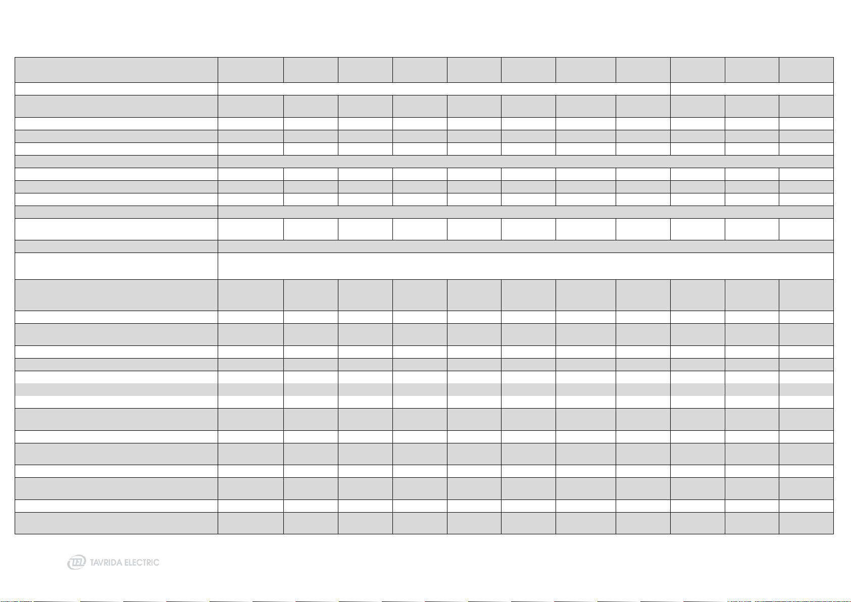
1.2 Main technical parameters
Main technical data and circuit breaker technical parameters are presented in the tables below.
Table 1 - Main technical parameters
Type
VCB15_LD1
VCB15_LD3
VCB15_LD6
VCB15_LD8
VCB15_MD1
VCB15_MD3
VCB15_Shell2
VCB15_HD1
VCB25_LD1
VCB25_LD2
VCB25_LD3
Rated voltage (Ur)
12 kV
17.5 kV
12 kV
12 kV
17.5 kV
17.5 kV
17.5 kV
17.5 kV
17.5 kV
24 kV
24 kV
24 kV
Rated normal current (Ir)
800 A
800 A
630 A
800 A
1250 A
1250 A
1250 A 1)
2000 A
2000 A 2)
3150 A 3)
800 A
800 A
800 A
Rated power frequency withstand voltage (Ud)
28 (42) 4)
kV
38 (42) 4)
kV
28 (42) 4) kV
28 (42) 4) kV
38 (42) kV 4)
38 (42) kV 4)
38 (42) kV 4)
38 (42) kV 4)
38 (42) kV 4)
50 kV
50 kV
50 kV
Rated lightning impulse withstand voltage (peak) (Up)
75 kV
95 kV
75 kV
75 kV
95 kV
95 kV 5)
95 kV 5)
95 kV 6)
95 kV
125 kV
125 kV
125 kV
Rated short-circuit breaking current (Isc)
20 kA 7)
20 kA 7)
20 kA 7)
20 kA 7
31.5 kA 7)
31.5 kA 7)
31.5 kA 7)
31.5 kA 7)
16 kA 7)
16 kA 7
16 kA 7)
Rated peak withstand current (Ip)
52kA
52kA
52kA
52kA
82 kA
82 kA
82 kA
82 kA
42 kA
42 kA
42 kA
Rated short-time withstand current (Ik)
20 kA
20 kA
20 kA
20 kA
31.5 kA
31.5 kA
31.5 kA
31.5 kA
16 kA
16 kA
16 kA
Rated duration of short circuit (tk)
4 s
4 s
4 s
4 s
4 s
4 s
4 s
4 s
4 s
4 s
4 s
Rated frequency (fr)
50/60 Hz
50/60 Hz
50/60 Hz
50/60 Hz
50/60 Hz
50/60 Hz
50/60 Hz
50/60 Hz
50/60 Hz
50/60 Hz
50/60 Hz
Mechanical life (CO-cycles)
50 000
50 000
20 000
50 000
30 000
50 000
30 000 8)
30 000 8)
30 000 8)
30 000
30 000 8)
Maximum number of CO-cycles per hour
60
60
60
60
60
60
60
60
60
60
60
Operating cycles, rated–short circuit breaking current
100
100
100
100
50
50
50
50
50
50
50
Closing time
≤ 70 9) ms
≤ 70 9) ms
≤ 70 9) ms
≤ 70 9) ms
≤ 60 9) ms
≤ 60 9) ms
≤ 60 9) ms
≤ 60 9) ms
≤ 60 9) ms
≤ 60 9) ms
≤ 60 9) ms
Opening time
≤ 35 9) ms
≤ 35 9) ms
≤ 35 9) ms
≤ 35 9) ms
≤ 35 9) ms
≤ 35 9) ms
≤ 35 9) ms
≤ 35 9) ms
≤ 35 9) ms
≤ 35 9) ms
≤ 35 9) ms
Break time
≤ 45 9) ms
≤ 45 9) ms
≤ 45 9) ms
≤ 45 9) ms
≤ 45 9) ms
≤ 45 9) ms
≤ 45 9) ms
≤ 45 9) ms
≤ 45 9) ms
≤ 45 9) ms
≤ 45 9) ms
Rated operating sequence at rated normal current
O-0.3s-CO-10s-CO-10s-CO 10)
Rated operating sequence at rated short-circuit
breaking current
O-0.3s-CO-15s-CO
Auxiliary circuits insulation strength 11)
Power frequency test voltage (1 min) according to
IEC60255-27
2 kV
2 kV
2 kV
2 kV
2 kV
2 kV
2 kV
2 kV
2 kV
2 kV
2 kV
Lightning impulse 1.2 m s/50 m s/0.5 J according to
IEC60255-27
5 kV
5 kV
5 kV
5 kV
5 kV
5 kV
5 kV
5 kV
5 kV
5 kV
5 kV
Insulation resistance, 1000V DC according to
IEC60255-27
≥ 5 MOhm
≥ 5 MOhm
≥ 5 MOhm
≥ 5 MOhm
≥ 5 MOhm
≥ 5 MOhm
≥ 5 MOhm
≥ 5 MOhm
≥ 5 MOhm
≥ 5 MOhm
≥ 5 MOhm
Design class of switching module with regard to
severity of service conditions in accordance with IEC
60932
Class 1
Class 1
Class 1
Class 1
Class 0
Class 0
Class 0
Class 0
Class 0
Class 1
Class 0
8
Type
VCB15_LD1
VCB15_LD3
VCB15_LD6
VCB15_LD8
VCB15_MD1
VCB15_MD3
VCB15_Shell2
VCB15_HD1
VCB25_LD1
VCB25_LD2
VCB25_LD3
Standards
IEC 62271-100 GB 1984- 2003
IEC 62271-100
Mechanical vibration withstand capability according to
IEC 60721-3-4
Class 4M4
Class 4M4
Class 4M4
Class 4M4
Class 4M4
Class 4M4
Class 4M4
Class 4M4
Class 4M4
Class 4M4
Class 4M4
Resistance of main circuit
≤ 40 μOhm
≤ 40 μOhm
≤ 40 μOhm
≤ 40 μOhm
≤ 17 μOhm
≤ 17 μOhm
≤ 18 μOhm
≤ 15 μOhm
≤ 40 μOhm
≤ 40 μOhm
≤ 40 μOhm
Weight (depending on Phase centre distance)
34-36 kg
13 kg
55 kg
26 kg
33-35 kg
13 kg
51-55 kg
70-72 kg
35-38 kg
35-37 kg
14 kg
Weight of CM
1 kg
1 kg
1 kg
1 kg
1 kg
1 kg
1 kg
1 kg
1 kg
1 kg
1 kg
Overall dimensions of CM 13)
190x165x45 mm
Altitude above sea level
1000 m 13)
1000 m 13)
1000 m 13)
1000 m 13)
1000 m 13)
1000 m 13)
1000 m 13)
1000 m 13)
1000 m 13)
1000 m 13)
1000 m 13)
Relative humidity in 24 hours
≤ 95 %
≤ 95 %
≤ 95 %
≤ 95 %
≤ 95 %
≤ 95 %
≤ 95 %
≤ 95 %
≤ 95 %
≤ 95 %
≤ 95 %
Relative humidity over 1 month
≤ 90 %
≤ 90 %
≤ 90 %
≤ 90 %
≤ 90 %
≤ 90 %
≤ 90 %
≤ 90 %
≤ 90 %
≤ 90 %
≤ 90 %
Temperature Range
-25 °C ... +55 °C
Degree of protection according to IEC 60529 of
actuator compartment
IP40
IP40
IP40
IP40
P40
P40
P40
P40
P40
P40
P40
Type of driving mechanism
Monostable magnetic actuator
Design, switching capacity of silver auxiliary
contacts
Number of available auxiliary contacts for three-phase
ISM
6 NO + 6 NC
2 NO + 2 NC
6 NO + 6 NC
Variable:
Up to
12NO+12NC
6 NO + 6 NC
2 NO + 2 NC
6 NO + 6 NC
6 NO + 6 NC
6 NO + 6 NC
6 NO + 6 NC
2 NO + 2 NC
Minimum current for 12 V AC / DC, ohmic load
100 mA
100 mA
100 mA
100 mA
100 mA
100 mA
100 mA
100 mA
100 mA
100 mA
100 mA
Minimum current for 12 V AC / DC, inductive load
(t=20 ms, cosj =0,3)
100 mA
100 mA
100 mA
100 mA
100 mA
100 mA
100 mA
100 mA
100 mA
100 mA
100 mA
Maximum current for 30 V DC, ohmic load
10 A 15)
10 A 15)
10 A 15)
10 A 15)
10 A 15)
10 A 15)
10 A 15)
10 A 15)
10 A 15)
10 A 15)
10 A 15)
Maximum current for 30 V DC, inductive load (t=20 ms)
3 A
3 A
3 A
3 A
3 A
3 A
3 A
3 A
3 A
3 A
3 A
Maximum current for 60 V DC, ohmic load
0.9 A
0.9 A
0.9 A
0.9 A
0.9 A
0.9 A
0.9 A
0.9 A
0.9 A
0.9 A
0.9 A
Maximum current for 60 V DC, inductive load (t=20 ms)
0.9 A
0.9 A
0.9 A
0.9 A
0.9 A
0.9 A
0.9 A
0.9 A
0.9 A
0.9 A
0.9 A
Maximum current for 125 V DC, ohmic load
0.5 A
0.5 A
0.5 A
0.5 A
0.5 A
0.5 A
0.5 A
0.5 A
0.5 A
0.5 A
0.5 A
Maximum current for 125 V DC, inductive load (t=20
ms)
0.03 A
0.03 A
0.03 A
0.03 A
0.03 A
0.03 A
0.03 A
0.03 A
0.03 A
0.03 A
0.03 A
Maximum current for 250 V DC, ohmic load
0.25 A
0.25 A
0.25 A
0.25 A
0.25 A
0.25 A
0.25 A
0.25 A
0.25 A
0.25 A
0.25 A
Maximum current for 250 V DC, inductive load (t=20
ms)
0.03 A
0.03 A
0.03 A
0.03 A
0.03 A
0.03 A
0.03 A
0.03 A
0.03 A
0.03 A
0.03 A
Maximum current for 125 V AC, ohmic load
10 A 14)
10 A 14)
10 A 14)
10 A 14)
10 A 14)
10 A 14)
10 A 14)
10 A 14)
10 A 14)
10 A 14)
10 A 14)
Maximum current for 125 V AC, inductive load
(cosj =0,3)
5 A
5 A
5 A
5 A
5 A
5 A
5 A
5 A
5 A
5 A
5 A
Maximum current for 250 V AC, ohmic load
10 A 14)
10 A 14)
10 A 14)
10 A 14)
10 A 14)
10 A 14)
10 A 14)
10 A 14)
10 A 14)
10 A 14)
10 A 14)
Maximum current for 250 V AC, inductive load
(cosj =0,3)
5 A
5 A
5 A
5 A
5 A
5 A
5 A
5 A
5 A

9
Type
VCB15_LD1
VCB15_LD3
VCB15_LD6
VCB15_LD8
VCB15_MD1
VCB15_MD3
VCB15_Shell2
VCB15_HD1
VCB25_LD1
VCB25_LD2
VCB25_LD3
Design, switching capacity of gold-plated auxiliary
contacts15)
Number of available auxiliary contacts for three-phase
ISM
-
-
-
-
-
-
-
-
6 NO + 6 NC
-
-
Minimum current for 5 V AC / DC
1 mA
1 mA
1 mA
1 mA
1 mA
1 mA
1 mA
1 mA
1 mA
1 mA
1 mA
Maximum current for 10 V AC / DC
300 mA
300 mA
300 mA
300 mA
300 mA
300 mA
300 mA
300 mA
300 mA
300 mA
300 mA
Maximum current for 30 V AC / DC
100 mA
100 mA
100 mA
100 mA
100 mA
100 mA
100 mA
100 mA
100 mA
100 mA
100 mA
Maximum voltage AC / DC
30 V
30 V
30 V
30 V
30 V
30 V
30 V
30 V
30 V
30 V
30 V
CM reaction times
Preparation time for the operation of the CM after
switching on the auxiliary power supply
≤ 15 s
≤ 15 s
≤ 15 s
≤ 15 s
≤ 15 s
≤ 15 s
≤ 15 s
≤ 15 s
≤ 15 s
≤ 15 s
≤ 15 s
Preparation time for the close operation of the CM after
a previous close operation
≤ 10 s
≤ 10 s
≤ 10 s
≤ 10 s
≤ 10 s
≤ 10 s
≤ 10 s
≤ 10 s
≤ 10 s
≤ 10 s
≤ 10 s
Preparation time for the trip operation of the CM after
switching on the auxiliary power supply
≤ 0.1 s
≤ 0.1 s
≤ 0.1 s
≤ 0.1 s
≤ 0.1 s
≤ 0.1 s
≤ 0.1 s
≤ 0.1 s
≤ 0.1 s
≤ 0.1 s
≤ 0.1 s
Trip capability after failure of the auxiliary power supply
≥ 60 s 16)
≥ 60 s 16)
≥ 60 s 16)
≥ 60 s 16)
≥ 60 s 16)
≥ 60 s 16)
≥ 60 s 16)
≥ 60 s 16)
≥ 60 s 16)
≥ 60 s 16)
≥ 60 s 16)
CM supply voltage
Rated range of supply voltage of
CM_16_1(Par1_60.1_Par2Par3_Par4_Par5)
24V to 60V DC
24V to 60V
DC
24V to 60V
DC
24V to 60V
DC
24V to 60V
DC
24V to 60V
DC
24V to 60V DC
24V to 60V
DC
24V to 60V
DC
24V to 60V
DC
24V to 60V
DC
Rated range of supply voltage of
CM_16_1(Par1_220.1_Par3_Par4_Par5)
110V to 220V AC/DC
Operating range (80-120%) of
CM_16_1(Par1_60.1_Par3_Par4_Par5)
19V to 72V DC
Operating range (80-120%) of
CM_16_1(Par1_220.1_Par3_Par4_Par5)
85V to 265V AC/DC
Power consumption of CM
Charging the close and trip capacitors of
CM_16_1(Par1_60.1_Par3_Par4_Par5)
≤ 25 W
≤ 25 W
≤ 25 W
≤ 25 W
≤ 25 W
≤ 25 W
≤ 25 W
≤ 25 W
≤ 25 W
≤ 25 W
≤ 25 W
Charging the close and trip capacitors of
CM_16_1(Par1_220.1_Par3_Par4_Par5)
≤ 42 W AC 17) ≤ 37 W DC
Permanent power consumption (standby) of
CM_16_1(Par1_60.1_Par3_Par4_Par5)
≤ 5 W
Permanent power consumption (standby) of
CM_16_1(Par1_220.1_Par3_Par4_Par5)
≤ 7 W AC 18) ≤ 5 W DC

10
Type
VCB15_LD1
VCB15_LD3
VCB15_LD6
VCB15_LD8
VCB15_MD1
VCB15_MD3
VCB15_Shell2
VCB15_HD1
VCB25_LD1
VCB25_LD2
VCB25_LD3
Inrush current of
CM_16_1(Par1_60.1_Par3_Par4_Par5) with
discharged capacitors
≤ 120 A
Inrush current of
CM_16_1(Par1_220.1_Par3_Par4_Par5) with
discharged capacitors
≤ 18 A
Inrush time constant of
CM_16_1(Par1_60.1_Par3_Par4_Par5) with
discharged capacitors
≤ 0.5 ms
Inrush time constant of
CM_16_1(Par1_220.1_Par3_Par4_Par5) with
discharged capacitors
≤ 4 ms
Design, switching capacity of CM inbuilt relays
Number of relays in CM
3
Number of available contacts for one relay
1 NO + 1 NC with common point
Rated voltage
240 V
240 V
240 V
240 V
240 V
240 V
240 V
240 V
240 V
240 V
240 V
Rated current AC
16 A
16 A
16 A
16 A
16 A
16 A
16 A
16 A
16 A
16 A
16 A
Maximum breaking power AC
4000 VA
4000 VA
4000 VA
4000 VA
4000 VA
4000 VA
4000 VA
4000 VA
4000 VA
4000 VA
4000 VA
Maximum switching current 250V DC
0.35 A
0.35 A
0.35 A
0.35 A
0.35 A
0.35 A
0.35 A
0.35 A
0.35 A
0.35 A
0.35 A
Maximum switching current 125V DC
0.45 A
0.45 A
0.45 A
0.45 A
0.45 A
0.45 A
0.45 A
0.45 A
0.45 A
0.45 A
0.45 A
Maximum switching current 48V DC
1.3 A
1.3 A
1.3 A
1.3 A
1.3 A
1.3 A
1.3 A
1.3 A
1.3 A
1.3 A
1.3 A
Maximum switching current 24V DC
12 A
12 A
12 A
12 A
12 A
12 A
12 A
12 A
12 A
12 A
12 A
Switching time
5 ms
5 ms
5 ms
5 ms
5 ms
5 ms
5 ms
5 ms
5 ms
5 ms
5 ms
“Close”and “Trip”dry contacts inputs of CM
Output voltage
≥ 30 V
≥ 30 V
≥ 30 V
≥ 30 V
≥ 30 V
≥ 30 V
≥ 30 V
≥ 30 V
≥ 30 V
≥ 30 V
≥ 30 V
Contacts closed current
≥ 50 mA
≥ 50 mA
≥ 50 mA
≥ 50 mA
≥ 50 mA
≥ 50 mA
≥ 50 mA
≥ 50 mA
≥ 50 mA
≥ 50 mA
≥ 50 mA
Steady state current
≥ 5 mA
≥ 5 mA
≥ 5 mA
≥ 5 mA
≥ 5 mA
≥ 5 mA
≥ 5 mA
≥ 5 mA
≥ 5 mA
≥ 5 mA
≥5 mA
1) For VCB ISM15_Shell with Low upper terminal –up to 1250 A, with High upper terminal –up to 2000 A.
2) Rating for metal enclosed switchgear with limited ventilation. Temperature rise type test at 2500 A in Cradle was successfully passed in KEMA.
3) 3150 A –for PCD 275 mm
4) The information in brackets refers to the national Chinese standards GB1984-2003 at an installation altitude of 1000 m maximum.
5) Parameter valid only when ISM is used with insulation kit. For details see dimensional drawings and accessory information
6) Parameter valid only when ISM is used with insulation caps. For details see dimensional drawings and accessory information.
7) At 40% d.c. component.
8) 10 000 CO –for ISM15_Shell_2(150_L) and ISM15_Shell_2(210_L) in horizontal actuator position.
9) Smaller timing on request
10) The number of sequential Close-Trip operations with a 10 second interval should not exceed 10. The number of Close-Trip operations should not exceed 60 per hour. Sequence of 10s Close-Trip operations can be repeated only after
260 s pause.
11) Isolation resistance check is not applicable for “Actuator Coil” circuits of CM.
12) Overall dimensions of ISM are given in „Appendix 3. Overall drawings“
13) Up to an installation altitude of 1000 m above sea level. Above 1000m, the external insulation measurement of the ISM must be increased by the atmospheric correction factor Ka according to IEC 62271-1 compared to the insulation
measurement at sea level. The maximum allowed altitude is 2000 m above sea level.

14) At 5 min short-term duty. Continuous current –5 A.
15) Gold-plated auxiliary contacts are availbale on request. Contact your nearest sales representatives.
16) In case of Dry contacts “Close” and “Trip” are open.
17) At Cos j >0.66.
18) At Cos j >0.33.

1.3 Disclaimers
Tavrida Electric will not accept any claims for damages caused by improper transport, storage as well as
unpacking. Transport damage must be reported in writing to the supplier as soon as it is discovered.
The present User Guide contains information necessary for the installation, commissioning and operation. It is
absolutely necessaryfor the proper use of the Vacuum Circuit Breakers to read the User Guide carefully before
starting and to adhere to the instructions and the relevant regulations. Tavrida Electric will not accept any
claims for damages caused by improper usage of the Vacuum Circuit Breakers. In case of special
configurations please contact Tavrida Electric prior of usage of the Vacuum Circuit Breakers.
1.4 Precautions
Check whether the installation position (distances, spatial separation, and the surroundings) is suitable
for the switching devices.
Installation, operation and maintenance shall only be carried out by trained and experienced personnel
who are familiar with the equipment and the electrical safety requirements.
During installation, commissioning, operation and maintenance of the equipment the relevant legal
regulations (such as DIN/VDE/IEC), accident prevention regulations and the connecting conditions of the
electric utilities shall be followed.
Take note that during operation of the Vacuum Circuit Breakers certain parts are subject to dangerous
voltage. Mechanical parts, also remote-controlled, can move quickly. Failure to comply may result in
death, severe personal injury or damage to equipment.
Pay attention to the hazard statements located throughout this User Guide.
The operating conditions of the vacuum circuit breakers shall comply with the technical data specified in
this User Guide.
Personnel installing, operating and maintaining the equipment shall be familiar with this User Guide and
its contents.
1.5 Warranty
Unless otherwise stated in the contract, the warranty period is stated in Standard warranty policy. If agreed to
otherwise, the contract conditions apply. No warranty is given in the case of …
a) … the warranty period having run out during the period of storage with the customer;
b) … the operating conditions, ambient conditions, transport and storage conditions have not been adhered
to according to the application description or the Installation and Operating Instructions;
c) … an unauthorized manipulation of the device has been carried out, such as opening the housing or
damaging the seal;
d) … the device has not been properly installed, such as incorrect connection of supply voltage of auxiliary
circuits.

13
2 Nameplates and seals

14
The Vacuum Circuit Breakers itself does not have nameplates or seals but main components (ISM, CM and
manual generators) it is comprised of have them.
ISM nameplates and seals
Each ISM has the following plate and labels:
Label
Serial number plate
Seals
Figure 1
ISM label
1. Manufacturer
2. Rated voltage Ur
3. Rated power frequency withstand
voltage Vd
4. Rated impulse withstand voltage Up
5. Applicable standards
6. ISM designation
7. Rated duration of short circuit tk
8. Rated short-circuit current Isc
9. Rated normal current Ir
10. Phase center distance p
11. Weight W
12. Year of manufacturing
13. Rated operating sequence
The serial number plate contains information about ISM type and serial number.
The label contains brief information about ISM technical parameters.
There are warranty seal labels on each side of the ISM metal frame.
Figure 2
Serial number plate
Figure 3
Warranty seal
Label, seal and serial number plate arrangement is shown below
1. Label
2. Serial number plate
3. Seal
a) ISM15_LD (except ISM15_LD_8)
and ISM25_LD labeling
b) ISM15_LD_8 labeling

15
c) ISM15_Shell_2 labeling
d) ISM15_MD_1 labeling
e) ISM15_HD_1 labeling
Figure 4
Serial number and designation label arrangement
CM nameplates and seals
Each CM has the following labels:
Serial number label
Label with applicable ISM designation
Warning label
Firmware version label
Information label with terminals connections and main parameters
Seals
Figure 5
Serial number label
Figure 6
Label with applicable ISM designation

16
Figure 7
Warning label
Figure 8
Firmware version label
Figure 9
Information label with terminals connections and main parameters
1. Serial number label
2. Label with applicable ISM designation
3. Warning label
4. Warranty seal
5. Firmware version label
6. Information label with terminals
connections and main parameters
Figure 10
CM labels placement
17
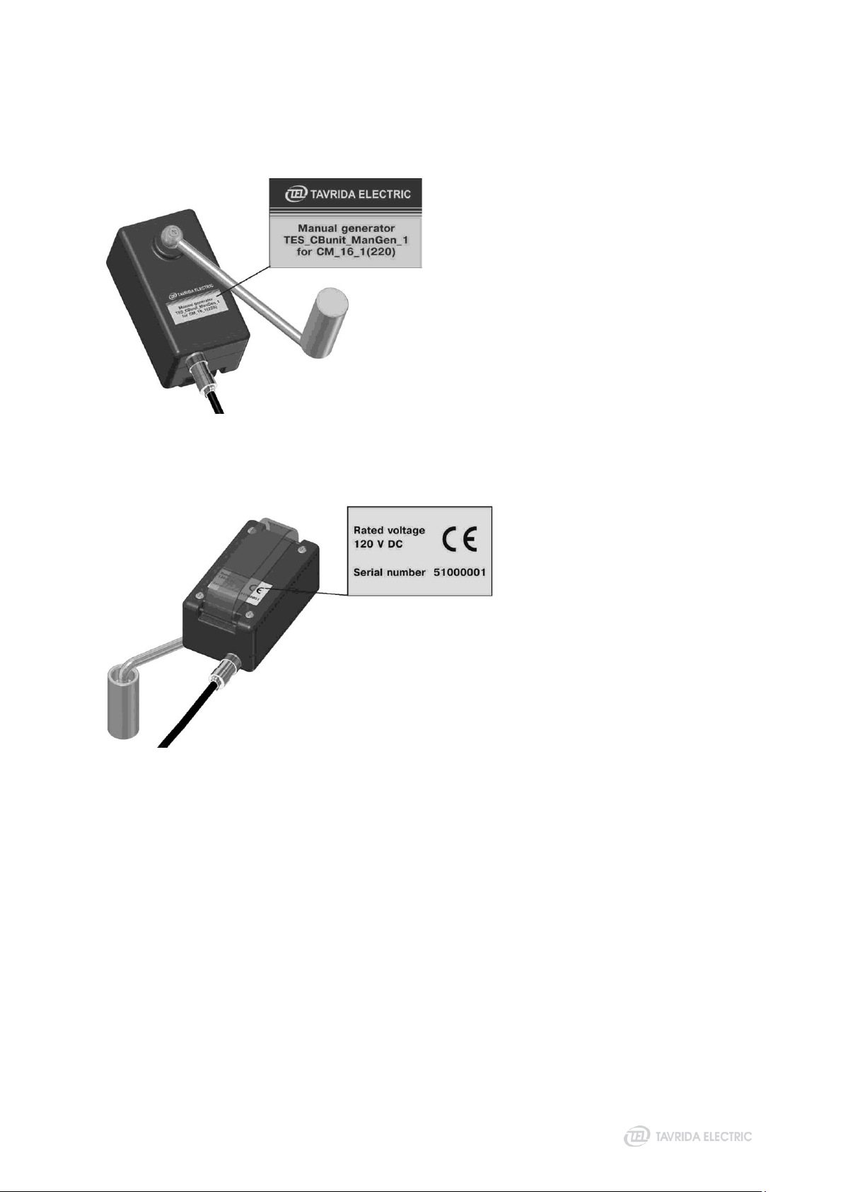
Manual generator nameplates
Each manual generator has the following labels:
Designation label
Serial number label
Figure 11
Designation label
Figure 12
Serial number label

18
3 Product handling

19
3.1 Transportation
The VCBs are transported in the original packing only. Any kind of transport and combinations thereof are
applicable. Transportation shall be provided in waterproof compartments. If air transport is used all products
shall be transported inside heated, pressurized compartments. The packed goods shall be handled in
accordance with the handling symbols. Loading procedures for VCB packaging shall be carried out only with
use of fork lifts, hoists or cranes. If possible the packaged VCB shall be placed on a pallet. During transportation
the VCB must not be subjected to sharp impacts or dropped.
3.2 Storage
If immediate installation is not possible, the VCB shall be stored in the original packing under the following
conditions:
the ISM is switched off;
desiccant must be placed in the packaging;
storage must be dry, well ventilated and the room temperature should be between - 25°C and + 55°C.
Average humidity measured over 1 year period shall not exceed 75% at 50ºC. If several VCBs are stacked a
maximum of two vertical layers are permitted
In case the storage term exceeds one year from the production date it is recommended to perform the procedu-
re of CM‘s electrolytic capacitor conditioning:
apply power to the CM for 20 seconds;
switch off the power supply and wait for 60 seconds;
repeat the above actions 2 times;
apply power to the CM continuously for 8 hours.
This procedure shall be performed annually during storage of the CM.
3.3 Unpacking and inspection
VCB unpacking and check
Before unpacking, check the carton for damage. Removal of the products from the original packaging must be
carried out with care and in accordance with lifting procedures. Every VCB component shall be checked for
completeness against the packing list included within the routine test certificate supplied with the CM and ISM.
These shall also be verified against the BOM list on the VCB packing list for VCB components and kits.
Unloading procedures for ISM shall be carried out only with use of hoists or cranes. Lifting gear must not be
attached to the support insulators; methods of lifting the ISM out of the carton shown below and must be strictly
followed.
Figure 13
Lifting of ISM15_LD_1, ISM15_LD_3, ISM15_LD_8,
ISM25_LD_1, ISM25_LD_2, ISM15_LD_3
Figure 14
Lifting of ISM15_Shell_2

20
Figure 15
Lifting of ISM15_HD_1
All items should be checked visually for:
mechanical damage, scratches, discoloration, corrosion;
damage to the seals Figure 3, Figure 5).
Any transport damage must be reported immediately to the carrier in writing. Damages shall be
photographically documented.
VCB packaging and scope of supply
The VCB are placed in cardboard boxes (Figure 18):
handling symbols label for transport and storage of the delivery unit (Figure 16);
labels for manufacturers and product information (Figure 19);
label for logistics data (Figure 17).
This manual suits for next models
11
Table of contents
Other TAVRIDA ELECTRIC Circuit Breaker manuals


Popular Circuit Breaker manuals by other brands


Eaton
Eaton VCP-W Instructions for installation, operation and maintenance

ABB
ABB DCBreak Series Instructions for installation & operation

Westinghouse
Westinghouse DBN-1016 Technical manual

WEG
WEG UBW600 user manual

Doepke
Doepke DFS 4 A EV Installation and operating instructions

Siemens
Siemens 3AH3 instruction manual