TAVRIDA ELECTRIC ISM_LD Series User guide

103
474
35
165 0,5±
50 0,2±
279
100 112
30
45
ISM_LD Series
Vacuum Circuit Breakers
15kV, ...20kA, ...1000A
27kV, ...16kA, ...800A
With CM_1501 and CM_16 Series Control Modules
Application Guide MAN5002252
Revision 1


The following application guide contains information necessary for the methods of
use, installation, commissioning and operation of the ISM_LD series of breakers.
It is absolutely necessary for the proper use of the vacuum circuit breakers to read
this guide carefully before starting and to adhere to the instructions as well as the
relevant regulations.
Safety first
· Check whether the installation position (distances, spatial separation, and the
surroundings) is suitable for the switching devices.
· Installation, operation and maintenance shall only be carried out by trained and
experienced personnel who are familiar with the equipment and the electrical
safety requirements.
· During installation, commissioning, operation and maintenance of the equipment
the relevant legal regulations, accident prevention regulations and the connecting
conditions of the electric utilities shall be followed.
· Take note that during operation of the vacuum circuit breakers certain parts are
subject to dangerous voltage. Mechanical parts, also remote-controlled, can move
quickly. Failure to comply may result in death, severe personal injury or damage
to equipment.
· Pay attention to the hazard statements located throughout this manual.
· The operating conditions of the vacuum circuit breakers shall comply with
the technical data specified in this manual.
· Personnel installing, operating and maintaining the equipment shall be familiar
with this manual and its contents.
For special configurations please contact TAVRIDA ELECTRIC NORTH AMERICA.

1
2
3
4
5
Table of Contents
1. Introduction
• Glossary.................................................................................................................................................7
• Scope ....................................................................................................................................................8
• Design and Method of Operation: ISM and CM ........................................................................................9
2. Receiving, Handling, and Storage
• Receiving............................................................................................................................................. 12
• Transport ........................................................................................................................................... 13
• Handling and Incoming Inspection....................................................................................................... 13
• Rating Plates, Warranty Seals ............................................................................................................... 14
3. Installation
• General, Preparation............................................................................................................................. 18
• Installation of the ISM......................................................................................................................... 18
• Minimum Clearances due to Rated Insulation Voltage ........................................................................... 20
• Measures for Complying with the Rated Insulation Level....................................................................... 20
• Minimum Clearances due to Electromagnetic Influence ......................................................................... 21
• Coordination of Minimum Clearances .................................................................................................... 21
• Heat Sinks for Continuous Current >800A ............................................................................................. 21
• Protective Earthing .............................................................................................................................. 22
• Mechanical Interlocking ....................................................................................................................... 22
• Secondary Connections of the ISM........................................................................................................ 26
• CM connections.................................................................................................................................... 28
• CM_16 Series Factory Programmable Options ........................................................................................ 30
• Installation of the CM: All Models ........................................................................................................ 32
• Installation of Secondary Cables Between ISM and CM: All Models ........................................................ 33
4. Switching and Control Functions
• Charging of the Capacitors ................................................................................................................... 35
• Ready-LED and Ready-Relay Output...................................................................................................... 35
• Malfunction-LED and Malfunction-Relay Output .................................................................................... 35
• Switching the ISM On and Off via the Dry Contact ............................................................................... 35
• Inputs of the CM.................................................................................................................................. 35
• Electrical Closing ................................................................................................................................ 35
• Lock-Out (Optional - CM1501 series) .................................................................................................... 35
• ISM Forced Trip by an Undervoltage Relay (Optional - CM_1501 Series)................................................. 36
• Output to Magnetic Actuator and Input for ISM Position Indication...................................................... 36
• Operations Counter .............................................................................................................................. 36
• Antipumping Duty................................................................................................................................ 37
• Blocking Duty ...................................................................................................................................... 37
• Combined Blocking and Antipumping Duty ........................................................................................... 37
5. Commissioning, Operation, Maintenance
• Safety.................................................................................................................................................. 39
• Commissioning Primary Part ................................................................................................................. 39
• Commissioning Secondary Part ............................................................................................................. 39
• Maintenance ........................................................................................................................................ 40
• Non-conformity.................................................................................................................................... 40
6. Signalling
• LED Indicators and Dry Contacts........................................................................................................... 42
• Malfunction Indication Table................................................................................................................ 43

6
7
8
9
10
11
12
7. Product Line
• Indoor switching modules (ISM)........................................................................................................... 46
• Control modules (CM15 Series) ............................................................................................................. 46
• Control modules (CM16 Series) ............................................................................................................. 46
8. Dimensions and Weights
• Dimensions and Weights of ISM............................................................................................................ 48
• Dimensions and Weights of the CM ....................................................................................................... 52
9. Circuit Diagrams
• ISM_LD with CM_16_1 Control Module.................................................................................................. 54
• ISM_LD with CM_1501_01 Control Module ............................................................................................ 55
10. Technical Data
• Indoor Switching Modules (ISM) - ANSI C37.09 .................................................................................... 57
• Indoor Switching Modules (ISM) - Additional Standards........................................................................ 58
• Control Modules ................................................................................................................................... 59
11. Regulations and Ambient Conditions
• Regulations.......................................................................................................................................... 64
12. Legal Information
• Warranty .............................................................................................................................................. 66
• Quality Regulations.............................................................................................................................. 66
• Complaints and Transport Damage........................................................................................................ 66
• Environmental Friendliness................................................................................................................... 67
• Non-Conformity Report ........................................................................................................................ 67
• Liability............................................................................................................................................... 67
• Copyright............................................................................................................................................. 67
• NON-CONFORMITY REPORT .................................................................................................................... 68

6
1
Introduction
1

7
1
Glossary
The following abbreviations are used in this operating manual:
AR: Automatic reclosing
CM: Control module
CO: Close open cycle
ISM: Indoor switching module
LED: Light emitting diode
MCB: Miniature circuit breaker
Make time
The make time is the time period from the energising of the closing circuit to the time when the current
begins to flow in the first pole.
Closing time
The closing time is the time period from the energising of the closing circuit to the time when all three
poles have contact.
Pre-arcing time
Interval of time between the initiation of current flow in the first pole during a closing operation and the
instant when the contacts touch in all poles for three-phase conditions and the instant when the contacts
touch in the arcing pole for single-phase conditions.
Opening time
The opening time is the time period from energising of the closing circuit up to the time when all the
switching poles are separated.
Break time
The break time is the time period from the energising of the closing circuit up to the time when the arcs
of all the poles are extinguished.
Open-close time (during AR)
Interval of time between the instant when the arcing contacts have separated in all poles and the instant
when the contacts touch in the first pole during a reclosing cycle.
Dead time (during AR)
Interval of time between final arc extinction in all poles in the opening operation and the first
reestablishment of current in any pole in the subsequent closing operation.
NC: Normally closed contact
NO: Normally open contact
PCD: Pole center distance
SCADA: Supervisory control and data aquisition
SF6: Insulating gas sulfur hexafluoride
VCB: Vacuum circuit breaker
VI: Vacuum interruptor

8
1
Scope
In comparison to conventional circuit breakers, the Tavrida Electric vacuum circuit breakers is comprised of two
components:
· The ISM (Figure 1)
· The CM for controlling the ISM (Figure 2)
Both modules must only be operated together and are meant for indoor installations only. The possibility to choose
the ISM and CM separately allows any type of switchgear to be easily equipped with regard to its primary and
auxiliary circuits.
This guide contains information on the operation, installation, commissioning and testing of the Tavrida
ISM_LD series of breaker products.
Figure 2
CM Module
Figure 1
ISM_LD type circuit breaker

9
1
2
1
3
4
5
6
7
8
9
10
13 11
14 12
15
16
17
1. VI
2. Upper terminal
3. Lower terminal
4.
Movable contact with bellows
5. Flexible junction shunt
6. Drive insulator
7. Opening springs
8. Contact pressure spring
9. Actuator coil
10. Armature
11. Magnetic actuator (complete module)
12. Interlocking pins
13. Stub shaft
14. Synchronizing shaft
15. Auxiliary contacts
16. Frame
17. Support insulator
Indoor Switching Module (ISM)
1. Terminals
2. LED indicators
3. Fastening holes
4.
Earthing stud
Control Module (CM)
Design and Method of Operation: ISM and CM
3
2
1
Figure 3
View into the ISM
Figure 4
Control Modules

10
1
Closing
In the open position the contacts are kept open by the force of the opening springs. To close
the contacts the coils of the magnetic actuators are excited by a current impulse from the close
capacitors of the CM. The opening springs are compressed when the contacts close. In the closed
position the contacts are kept closed only by means of the magnetic force. The ISM maintains the
closed position without mechanical latching even in the event of a failure of the auxiliary power
supply (Figure 5).
Opening
To open the contacts a current impulse in the reverse polarity derived from the opening capacitors
of the CM is injected in the coils of the magnetic actuators, releasing the magnetic holding force.
The compressed opening springs and contact pressure springs open the contacts (Figure 5).
Manual-Emergency-Tripping
The ISM can also be manually opened. When the synchronizing shaft is rotated, a force exceeding
the magnetic attraction forces of the ring magnet is applied to the armature, which subseqently
starts to move. As the air gap increases, the opening springs and the contact pressure springs
overcome the magnetic holding force, and the vacuum interrupter opens.
Manual Closing
The ISM can only be closed electrically via the CM. In the case of a failure of auxiliary power
supply the contacts can be closed using an alternative auxiliary power supply such as a battery.
Mechanical closing is not possible and leads to the destruction of the ISM.
Position main
contacts
Actuator coil
current
Anchor travel
Anchor velocity
Open
Closed
Open
Closed
0
0
0
Close command CM (dry contact)
Close impuls to ISM-coils
Start anchor movement
ISM main contacts closed
Stop anchor movement
Switch off actuator
current for close operation
Trip command CM
(dry contact)
Trip impuls to ISM-coils
ISM main contacts open
Open position kept by
opening springs
0 20 40 60 80 100 120 140 160
Time (ms)
1
Figure 5
Typical oscillogram of ISM operation

11
2
Receiving, Handling,
and Storage

12
2
Receiving
The following information is provided on the ISM packing cartons (Figure 9):
· Handling symbols for transport and storage of the delivery unit (Figure 6)
· Label 1 for manufacturers´ and product information (Figure 7)
· Label 2 for logistics data (Figure 8)
35522
Mark:
Place of delivery:
Consignee:Address
Address
Address
Address
Address
Phone:
Contact person
P/O Number: Customer reference
Article: Article description
Serial Number: 50509
Consignee:
3 421 1. This side up
2. Fragile
3. Protect from rain
4.
Max. weight on
the delivery unit
5. Serial number
5
A label with the following information is fixed on each CM carton package (Figure 10).
1 2
3
4
5
6
1. Manufacturer
2. Product name
3. Type of device
4.
Serial number
5. Product code
6.
Carton package for
CM_1501_01(12)
A CM carton package must not have a weight of more than 30 kg applied to it.
17.10.2011
Figure 6
Handling Symbols
Figure 7
Product Information Label
Figure 8
Logistics Data Label
Figure 9
ISM Package
Figure 10 _
CM Package and Label
()
ISM15_LD_1(55)

13
2
Transport
ISM and CM shall be transported in the original packing only. The packed goods shall be handled in accordance with
the handling symbols. Loading procedures for ISM packing units shall be carried out only with fork lifts or cranes. If
possible the ISM packing unit shall be placed on a pallet. Lifting gear must not be attached to the support insulators.
During transportation the ISM and CM must not be hit or dropped.
Handling and Incoming Inspection
Before unpacking, please check the carton for damage and dampness. Removal of the products from the original
packing must be carried out with due care. Every ISM and every CM shall be subject to an incoming inspection.
Circuit breaker modules are heavy. Always use two people to lift out of the original packaging, with due care
and attention to safe lifting procedures.
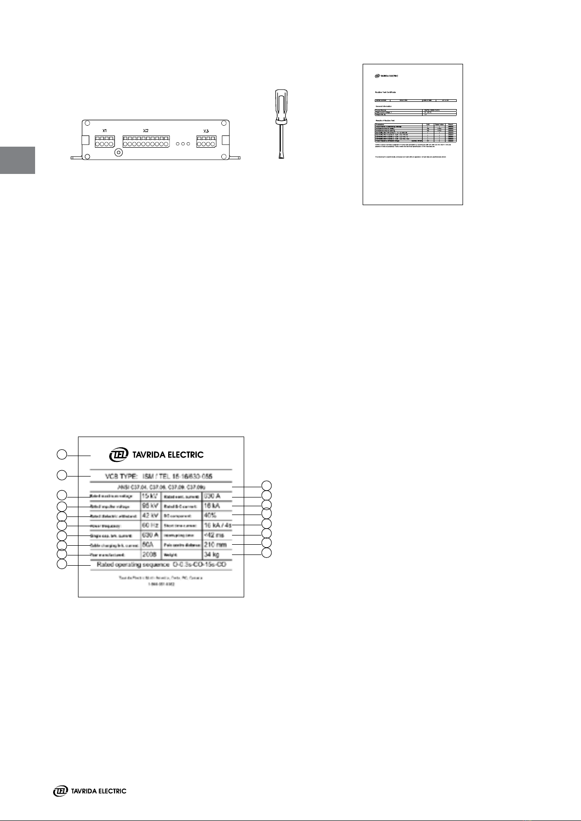
Scope of delivery for the ISM:
ISM Screwdriver Operating manual Routine test certificate
Figure 11
When requested for 1000A operation, the ISM15_LD_1 and LD_3* require a heat sink set.
6x 12x
Heat sink
ITEA 741394.006
Bolts
ITEA 301611.004-03
2x 4x
Heat sink
ITEA 741394.006
Bolts
ITEA 301611.004-03
The ISM25_LD_1 and LD_3* require an insulating cap set.
3x 3x
Lower cover part
ITEA 711671.004
Sealing ring
ITEA 754152.002
3x 3x
Cap for upper
connecting bolt
ITEA 711121.002
Upper cover part
ITEA 714323.001
1x 1x
Lower cover part
ITEA 711671.004
Sealing ring
ITEA 754152.002
1x 1x
Cap for upper
connecting bolt
ITEA 711121.002
Upper cover part
ITEA 714323.001
Figure 12
Figure 13
*included
*included
14
2
Scope of delivery for the CM:
CM Screwdriver Routine test certificate
Figure 14
The intactness of the devices should be checked visually for:
· Mechanical damage, scratches, discolouration, corrosion
· Damage to the seals (Figure 19, Figure 20)
Any transport damage must be reported immediately to the carrier in writing.
Cases of damage must be photographically documented.
Rating Plates, Warranty Seals
Please check that the rating plates of the delivered devices correspond to the data of the order. The rating plate
for the ISM contains the following information (Figure 15):
1. Manufacturer
2. Type of device
3. Rated maximum voltage
4.
Rated impulse withstand voltage
5. Rated dielectric withstand voltage
6.
Rated frequency
7. Single capacitor bank breaking current
8.
Cable charging breaking current
9. Year manufactured
1
2
3
4
5
6
9
10
Figure 15
Rating plate
7
8
11
12
13
14
15
16
17
18
10.
Rated operating sequence
11. Applicable ANSI standards
12. Rated continuous current
13. Rated short circuit current
14. DC component percentage
15. Rated short time current
16. Interrupting time
17.
Pole centre distance
18. Weight
15
2
2
The rating plates for the CM1501 series contain the following information (Figure 16):
Breaker Control Module
Model CM_16_1(60)
Power Supply Input
19-72
25 W for 10s (charging)
5 W steady state
Input must be
protected by a two pole
miniature circuit breaker
rated: 4A, type B or C
Fault / Ready Relays
Max 240 16A
See circuit breaker
applications manual for
detailed information and
DC load break capacity.
Operating Conditions
-40C to +55C ambient
IP40 degree of protection
Operating Duty
O-0.3s-CO-10s-CO-10s
Conforms to
UL STD 508
Certied to
CAN/CSA-22.2 No.
142-M1987
Tavrida Electric North America
1105 Cliveden Ave, Delta, BC, Canada
1-866-551-8362
Made in Russia
4000068
1
2
3
4
5
4
6
7
8
9
1. Model type
2. Auxiliary power supply min / max
3. Power consumption
4.
Warning notes
5. Output contact maximum voltage / current
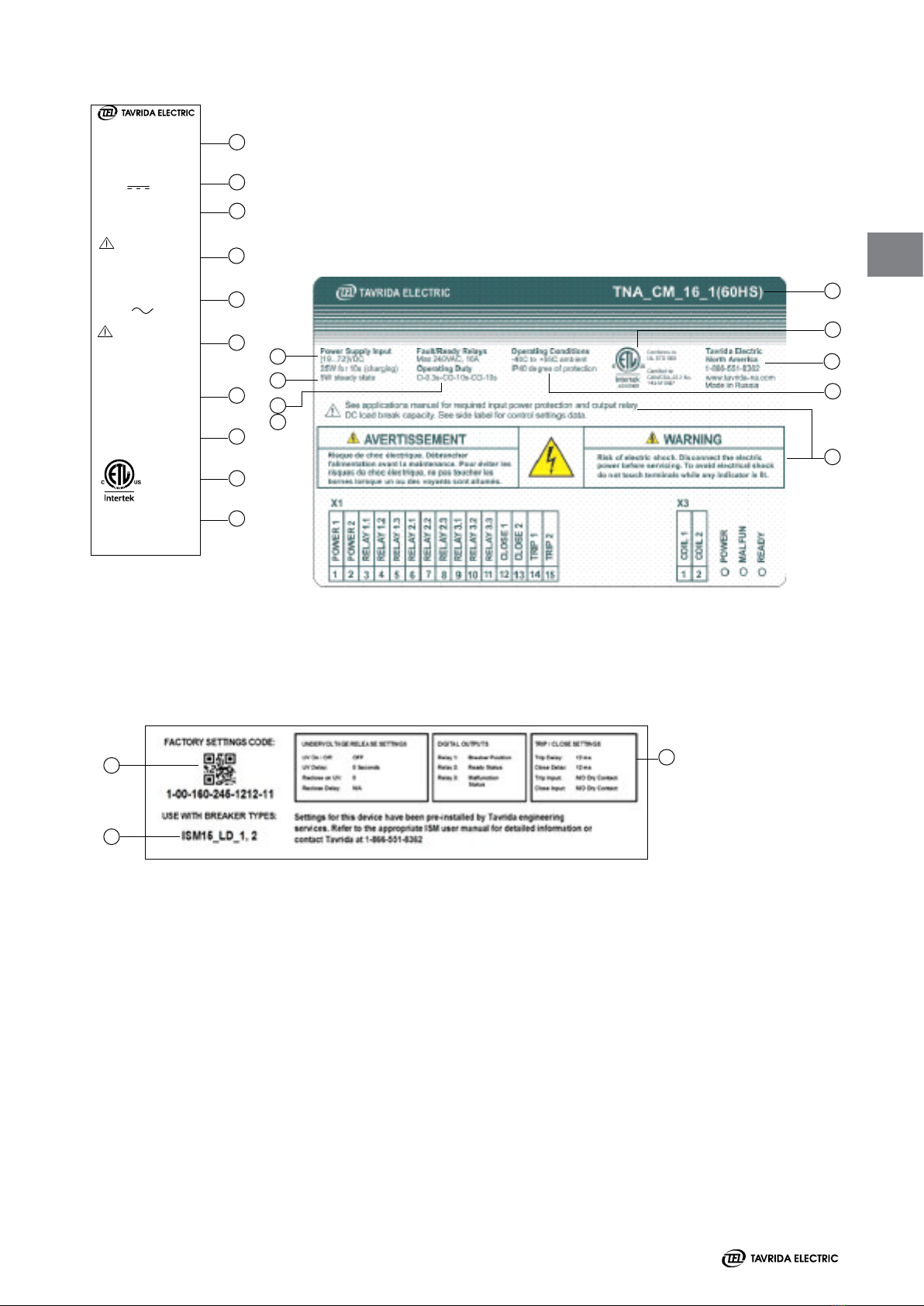
The rating plate for the CM16 series contain the following information (Figure 17):
1
2
3
4
5
6
7
8
9
The CM_16 has an additional label for factory programmable settings (Figure 18); see page 31 for detailed
information on the settings functions.
1
2
1. Settings
2. QR code (scannable settings code)
3. Applicable breaker type
3
6.
Operating conditions
7. Operating duty cycle
8.
NRTL listing / conformance mark
9. Contact information
Figure 16
Figure 17
Figure 18

16
2
Storage
Should immediate installation not be possible, the ISM and CM shall be stored in the original packing under the
following conditions:
· The ISM is switched off.
· Dessicants must be placed in the packing.
· Storage must be dry, well ventilated and the room temperature should be between - 40°C and + 40°C
· If several ISM are stacked a maximum of two vertical layers is permitted.
· If several CM are stacked a maximum of 10 vertical layers is permitted.
If CM are stored longer than one year, the built-in capacitors shall be charged according to the following procedure before
putting into operation:
· Switch On auxiliary power supply to CM for 20 seconds.
· Switch Off auxiliary power supply to CM for one minute.
· Repeat the described switching on and off procedure two times.
· Switch On auxiliary power supply to CM for at least 8 hours.
2
13 321
65
1
4
3
2
Arrangement of the labels (Figure 18, Figure 19):
ISM
1. Rating plate
2. Serial number
3. Warranty Seal
CM
1.
Seal
2. Serial Number, date of manufacturing
3.
Product code
Figure 19
Labelling three-phase ISM Labelling single-phase ISM
Figure 20
Labelling of the CM1501
2
13 321
65
1
4
3
2
The manufacturer accepts no warranty for a device if the seal is broken or has been removed.
2
3
1

17
Installation 3

18
3
ISM Installation
General, Preparation
All applicable regulations must be adhered to during installation, commissioning and operation, including
ANSI, IEEE, CEC, NEC, and other local, national or international standards / codes as required. Work shall
only be performed by qualified personnel.
The wearing of gloves for handling the parts during installation
is recommended.
Insulating material surfaces must be cleaned with clean and
dry rags. The contact surfaces of connections must be cleaned
before installation. If the contacts have become oxidized during
transport or storage then the following sequence must be
followed:
· Clean contact surfaces with a rough, dry cloth.
· With hard oxidation, clean with a hard plastic sponge,
the upper layer must not be removed.
Nuts, washers and conical spring washers shall be used for
connecting the upper terminals of the ISM with the busbars.
The lower terminals of the ISM shall be connected with the
same connecting elements.
If additional fastening material is required, steel bolts according
to EN ISO 898 class 8.8 (800 N/mm²), nuts according to EN ISO
890 class 8 (880 N/mm²), washers to DIN 125 and conical spring
washers to DIN 6796 shall be used.
ISM mounting and connection shall be made with dynamometic
wrench only.
Installation of the ISM
All LD series can be installed in any position (Figure 21). The ISM
shall be installed at the place designated for it (Figure 21) on a
sufficiently stable frame.
In order to prevent bending loads at the support insulators the
poles must be fixed as shown in Figure 22.
The torque of all fixing points shall not exceed the values stated
in Figure 23.
Vertical installation position
of the ISM (draw out type)
Vertical installation position
of the ISM (draw out type)
Horizontal installation position
of the ISM (draw out type)
Figure 21

19
Bolt sizes and torques
~
4C
Nut M1 0
Contact surface Wa sher
Conical spring washer
~
4B
4A
Installation of the ISM
in xed position
Installation of the ISM in
withdrawable position
Fixing points, primary terminals
Required fixing points
(in each case)
1
Bus bars and cables shall be connected with the ISM primary terminals mechanically in a stress-free manner.
No pressure, tension or torsion forces shall act on the ISM. To avoid unacceptably high mechanical loads on the ISM,
the bus bar connections shall rest on additional supporting insulators (Figure 22).
The following limits for maximum unsupported busbar length shall be applied to the design:
ISM15_LD_X 0.5 m
ISM25_LD_X 0.5 m
Other dimensions necessary for correct mounting are indicated in the overall drawings.
Figure 22
Figure 23
Terminals:
M10 stud
Torque 30 3 Nm
Fixing points:
Internal thread M16
Torque 70 7 Nm
Fixing points:
Internal thread M1 0
Torque 30 3 Nm
+
_
+
_
+
_
Terminals:
holes Ø 10.5 mm
Required fixing points
(for withdrawable versions)
Each two fixing points are required,
either 4A+4B or 4A+4C (for fixed
installations)
3
2
3

20
a
Metal housin g
a
a
Minimum Clearances due to Rated Insulation Voltage
The minimum clearances between the
blank phases and to earth shall be
according to VDE 0101.
The minimum clearances between phase to
phase and phase to earth are equal (Figure
24).
If the insulation cap set will not be used
the compliance with the rated insulation
level shall be approved by a voltage test.
UrUpMinimum
clearance (a)
15 kV 95 kV 120 mm
27 kV 125 kV 220 mm
Figure 24
Measures for Complying with the Rated Insulation Level
Insulation cap set for 27 kV ISM
To comply with the rated impulse
withstand voltage of 125 kV according
to ANSI 37.09 it is recommended to
cover the top connections of the 27kV
ISM with an insulation cap set.
The insulation cap set is included in the
scope of supply of the affected ISM.
The arrangement is shown in Figure 25.
Figure 25
Busbar for 27 kV ISM
If the PCD of the 27kV ISM is 210 mm, the
connected bus bars shall have the shape
as shown in Figure 26. 40
R5
10
Figure 26
Phase segregation plates
for 15 kV and 27 kV ISM
For 15 kV ISM with a PCD of 150 mm or
27 kV ISM with a PCD of 210 mm it is
recommended to use segregation plates
between the poles. Minimum size and
position of the plates are shown in
Figure 27.
If the plates will not be used the compli-
ance with the rated insulation level shall
be approved by a voltage test.
The segregation plates are not included in
the scope of supply. Recommended size and position of
the segregation plates for ISM, 15 kV
PCD 150 mm
Recommended size and position of
the segregation plates for ISM, 27 kV
PCD 210 mm
265
370
150
265
400
150
Figure 27
Section AA
45
°
A
A
A
A
Upper cover par t
Sealing ring
Support insulator
Cap for upper
connecting bolt
Lower cover par t
A
A
A
A
Upper cover par tSealing ring
Support insulator
Cap for upper
connecting bolt
Lower cover par t
3
This manual suits for next models
3
Table of contents
Other TAVRIDA ELECTRIC Circuit Breaker manuals


Popular Circuit Breaker manuals by other brands


Reliance Controls
Reliance Controls Panel/Link TC Series quick start guide

Westinghouse
Westinghouse DBN-1016 Technical manual

Xantrex
Xantrex PROwatt 1750 Addendum owner's guide

Siemens
Siemens 3WX3647-5JE00 operating instructions

Eaton
Eaton IZM Series installation instructions

Eaton
Eaton NZMB Series Instruction leaflet


