Taylor CD-i User manual

V-21A
TAYLOR
STUDWELDING
SYSTEMS LIMITED
OPERATING GUIDE
FOR
TYPE CD-i
CAPACITOR DISCHARGE
STUDWELDING EQUIPMENT
A TAYLORMADE CAPACITOR DISCHARGE STUDWELDING SYSTEM

V-21A
INDEX
2
PAGE No. CONTENT
3USEFUL INFORMATION.
5IMPORTANT SAFETY INFORMATION.
7INTRODUCTION TO STUDWELDING.
8GUIDE TO EXTERNAL FEATURES.
10 SETTING UP AND WELDING.
12 WELD SETTINGS.
14 WELD TESTING.
15 PARTS LIST & EXPLODED DIAGRAMS.
22 CIRCUIT SCHEMATIC - WIRING.
23 DECLARATION OF CONFORMITY.

V-21A
USEFUL INFORMATION
3
MANUFACTURERS DETAILS
TAYLOR STUDWELDING SYSTEMS LIMITED
COMMERCIAL ROAD
DEWSBURY
WEST YORKSHIRE
WF13 2BD
ENGLAND
TELEPHONE :+44 (0)1924 452123
FACSIMILE :+44 (0)1924 430059
email :sales@taylor-studwelding.com
WEB :www.taylor-studwelding.com
SALES DIRECT TEL :+44 (0)1924 487703
TECHNICAL HELPLINE :+44 (0)1924 487701
You may wish to record the details of your controller below as this informaon will help
with any technical assistance you may require:
PURPOSE AND CONTENT OF THIS GUIDE
This guide has been wrien for :
• The personnel of the end-user responsible for the installaon and maintenance of the
controller.
• The operator of the welding controller.
This guide contains informaon relang to :
• Installaon and connecon.
• Operaon.
• Technical specicaons and parameters.
• Spare parts.
CONTROLLER SERIAL No.
DATE PURCHASED.

V-21A
USEFUL INFORMATION
4
FURTHER INFORMATION
Should you require addional technical informaon, please contact us directly (details
on previous page) or our local agent / distributor (details of agents etc. can be obtained
from us).
This guide contains important informaon which is a pre-requisite for safe Operaon
of the equipment. The operang personnel must be able to consult this guide when
necessary. In the interests of safety, make this guide available to your personnel in good
me.
If the equipment is sold / passed on, please hand over this manual to the new owner
and if possible please inform us of the name and address of the new owner, in case we
need to contact him regarding the safety of the machine.
PLEASE READ THIS GUIDE CAREFULLY BEFORE INSTALLING OR OPERATING THE
CONTROLLER.
PLEASE OBSERVE CAREFULLY ALL SAFETY PROCEDURES/INSTRUCTIONS.
THIS EQUIPMENT HAS BEEN EMC TESTED AND APPROVED IN ACCORDANCE
WITH BS EN 60974-10 (CATEGORY 2).
THIS MACHINE OPERATES FROM A MAINS SUPPLY OF 100-250V AC @ 50Hz
NEVER REMOVE ANY PORTION OF THE UNIT HOUSING WITHOUT FIRST
ISOLATING THE CONTROLLER FROM THE MAINS ELECTRICAL SUPPLY.
NEVER OBSTRUCT THE UNDERSIDE, FRONT OR REAR PANELS AS THIS MAY
CAUSE THE UNIT TO OVERHEAT DURING OPERATION.
DO NOT USE THIS WELDING POWER SOURCE FOR PIPE THAWING.
Taylor Studwelding Systems Limited reserves the right to amend the contents of this guide without nocaon.

V-21A
IMPORTANT SAFETY INFORMATION !
5
PROTECT YOURSELF AND OTHERS !
Read and understand these safety notes.
1. ELECTRICAL
No poron of the outer cover of the welding controller should be removed by anyone other
than suitably qualied personnel and never whilst mains power is connected. ALWAYS
disconnect the mains plug from the socket.
BE AWARE ! Capacitors store electrical energy. Check for residual
charge before carrying out any internal maintenance.
DO NOT ! use any uids to clean electrical components as these
may penetrate into the electrical system
Installaon must be according to the seng up procedure detailed on page 10 of this
manual and must be in line with naonal, regional and local safety codes.
2. FIRE
During welding small parcles of very hot metal are expelled. Ensure that no combusble
materials can be ignited by these.
3. PERSONNEL SAFETY
Arc rays can burn your eyes and skin and noise can damage your hearing. Operators and
personnel working in close proximity must wear suitable eye, ear and body protecon.
Fumes and gases can seriously harm your health. Use the equipment only in a suitably
venlated area. If venlaon is inadequate, then appropriate fume extracon equipment
must be used.
Hot metal spaer can cause re and burns. Appropriate clothing must be worn. Clothing
made from, or soiled with, combusble materials must NOT be worn.
Have a re exnguisher nearby and know how to use it.
Magnec elds from high currents can aect heart pacemakers or other electronically
controlled medical devices. It is imperave that all personnel likely to come into the vicinity
of any welding plant are warned of the possible risks before entering the area.
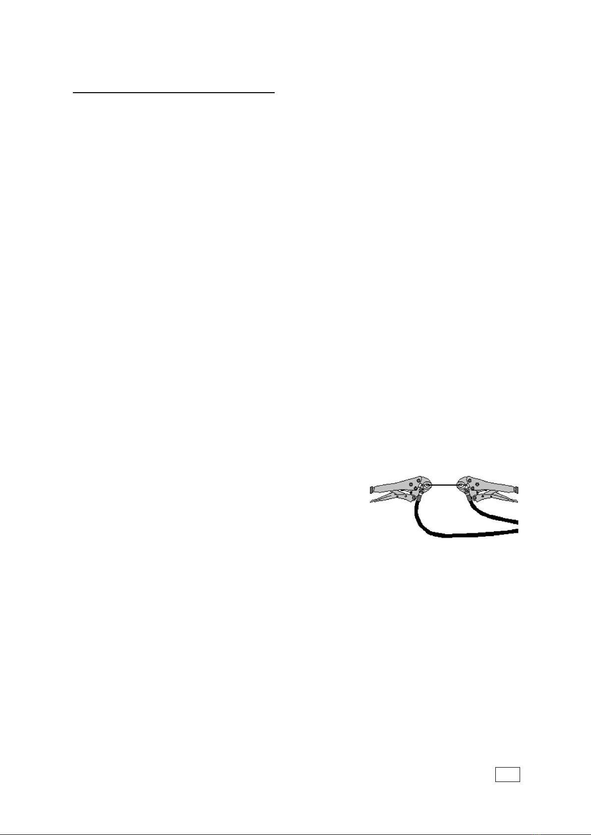
To minimise the risks of exposure to electromagnec radiaon, operators should not drape
the welding cables over their shoulders or wrap them around themselves in any way whilst
using the equipment. It is also recommended that operators route the welding earth return
cables away from themselves and do not stand between the two earth return cables during
welding.

V-21A
IMPORTANT SAFETY INFORMATION !
6
4. MAINTENANCE
All cables must be inspected regularly to ensure that no danger exists from worn or
damaged insulaon or from unsound electrical connecons. Special note should be made
of the cables close to the pistol, where maximum wear occurs. As well as producing
inconsistent welds, worn cables can overheat or spark, giving rise to the risk of re.
5. LIMITATIONS OF USE
The mass of the welding controller is between 11 and 13.3kg dependant on the model
purchased and as such is suitable to be manhandled. The controller is not suitable for use in
rain or snow or in an environment with increased risk of electric shock.
6. TRAINING
Use of the equipment must be limited to authorised personnel only who must be suitably
trained and must have read and understood this manual. This manual must be made
available to all operators at all mes. Further copies of this manual may be purchased from
the manufacturer. Measures must be taken to prevent the use of this equipment by
unauthorised personnel.
7. INSTALLATION
Ensure that the site chosen for the equipment is able to support the weight of the
equipment and that it will not fall or cause a danger in the course of its normal operaon.
Do not hang connecng cables over sharp edges and do not install connecng cables near
heat sources or via trac routes where people may trip over them or they may be
damaged by the passage of vehicles (forklis etc.)
8. INTERFERENCE
During welding operaons, intense magnec and electrical elds are unavoidably produced
and these may interfere with other sensive Electronic equipment.
All Taylor Studwelding equipment is designed, manufactured and tested to conform the
current appropriate European standards and direcves regarding electromagnec
emissions and immunity and as such is safe to use in any normal environment.
9. DISPOSAL
The equipment either wholly or any of its component parts may be disposed of as part of
general industrial waste or passed to a scrap merchant. None of the components used in
the manufacture are toxic, carcinogenic or harmful to health in their “as supplied”
condion.

V-21A
INTRODUCTION TO STUDWELDING
7
INTRODUCTION
The complete range of Taylor Studwelding Systems Capacitor Discharge units are
compact, portable Stud Welding equipment's. The units are specically designed to enable
a small diameter range of ferrous and non-ferrous weld studs to be welded to light gauge,
self-nish or pre-coated materials, in most cases with lile or no reverse marking.
The equipment consists of a control unit, a welding pistol and the necessary
interconnecng cables and accessories.
THE PROCESS
Capacitor Discharge stud welding is a form of welding in which the energy required
for the welding process is derived from a bank of charged capacitors. This stored energy is
discharged across the gap between the two surfaces to be welded as they are propelled
towards each other. The arc produced heats the two surfaces, melng a thin lm of metal
on each surface and the propelling force closes the gap between the two faces, thus
forming a weld.
In contact welding the stud to be welded is forced by spring pressure on to the plate.
At this point the arc gap between the two components is maintained by a small pip on the
welding face of the stud. On iniaon of the high current pulse from the capacitors, this pip
vaporises and an arc is drawn between the work piece and the stud. The heat from this arc
melts the base of the stud and the area of the work piece directly beneath the stud, whilst
the spring pressure from the pistol accelerates the stud towards the work piece. Within 3
to 4 milliseconds the stud hits the work piece and the arc is exnguished. The kinec
energy contained in the moving stud and the remaining spring pressure, forge the molten
parts together to form a weld.

V-21A
GUIDE TO EXTERNAL FEATURES
8
FRONT PANEL
1. CARRYING HANDLE
2. WELDING VOLTAGE DISPLAY
3. WELDING VOLTAGE CONTROL KNOB
4. VENTILLATION HOLES ! DO NOT OBSTRUCT !
5. WELDING EARTH PANEL CONNECTOR
6. GREEN LED - INDICATES READY TO WELD
7. AMBER LED - INDICATES UNIT IS CHARGING
8. RED LED - INDICATES UNIT IS IN RESET MODE. WAIT 10 SECONDS AND RE-START THE
CONTROLLER WITH THE ON/OFF SWITCH. IF THE RESET CONDITION PERSISTS A FAULT
HAS OCCURED
9. WELDING PISTOL CONTROL CONNECTOR
10. WELDING PISTOL PANEL CONNECTOR
1
2
3
4
5
6
7
8
9
10

V-21A
GUIDE TO EXTERNAL FEATURES
9
BACK PANEL
1. RATING/SERIAL PLATE 4. MAIN FUSE
2. ON/OFF SWITCH 5. MAINS INLET - IEC SOCKET OR
3. VENTILLATION FAN/GRILLE - ! DO NOT OBSTRUCT ! FIXED CABLE (SEE INSET)
OPTIONS AVAILABLE
IMPORTANT NOTES !
Due to the power requirements and Electromagnec emissions produced during normal use, this
machine must only be operated in an industrial environment.
The unit has inverter technology and is designed to operate from any single phase AC voltage between
100 and 250VAC at 50Hz.
Never obstruct the front and rear panel venlaon holes or the underside of the unit as this may cause
the unit to overheat during operaon.
Never remove any poron of the unit housing without rst isolang the unit from the mains electrical
supply.
1
2
3
4
5

V-21A
SETTING UP AND WELDING
10
Set up the control unit at the place of work,
ensuring that the mains switch is in the OFF
posion. Ensure that this is done in line with the
notes and safety recommendaons on pages 5 and
6 of this manual.
Plug the controller into the
correct mains AC supply. The
controller is rated for any single
phase AC voltage between 100
and 250VAC at 50Hz. Ensure
the correct plug is ed for
your supply in line with local/
naonal codes.
Connect the welding earth cable to the controller panel
mounted plug.
Note that the cable end plug has a peg which mates with a
key slot in the panel mounted socket.
IMPORTANT !
Secure the connector with a
clockwise turn unl it locks.
Failure to do this will result in
damage to the connector
during welding.
Aach the welding earth clamps to the work piece at
approximately 180° to each other. This will help to prevent
"Arc blow" when welding takes place. Prior to ng the
clamps, ensure that the contact area of the work piece is
free from rust, paint, grease etc. As this will result in a poor
welding connecon and poor results. Where possible, route
the earth cables away from the operator to prevent the operator being posioned between
the run of the cables whilst operang the equipment.
Connect the welding pistol cable to the controller panel
mounted socket.
Note that the cable end plug has a peg which mates with
a key slot in the panel mounted socket.
IMPORTANT !
Secure the connector with
a clockwise turn unl it
locks. Failure to do this
will result in damage to
the connector during

V-21A
SETTING UP AND WELDING
11
Connect the welding pistol control cable to the
panel mounted socket on the controller.
Note that the cable end plug and panel mounng
socket are keyed to prevent incorrect ng. Push
the plug rmly home and twist the locking ring
clockwise to secure the plug in posion.
Prepare the pistol for use in accordance with the guidance given in the document
“OPERATING GUIDE FOR CD STUDWELDING PISTOLS TYPE C2 & LG2” which accompanies
the type C2 pistol supplied with your controller.
The guide contains informaon on :
• Pistol Setup
• Spare Parts
• Accessories
• Safety

V-21A
WELD SETTINGS
12
This page and the following are intended as a guide to seng your machine.
The sengs outlined in the table are only intended as a starng point. It is possible that the
sengs will give sasfactory results without adjustment, but in reality the quality of the
welding results is governed by many variable factors. These include, most obviously, the
welding power and pistol spring pressure as covered in the table, but can also include
factors such as stud and work-piece material type and condion, ambient temperature,
relave humidity, quality of supply etc. All of these factors can act on the weld to change
the outcome. It is recommended that in all instances, you need to carry out sample welds
in your actual condions and environment. This will enable you to alter the sengs, where
necessary, to achieve welds that are most acceptable to you.
The seng charts were established with the performance of repeve weld tests using
studs manufactured to the BS EN ISO 13918 standard, in the following materials :
Mild Steel, Grade St37-3
Stainless Steel, Grade 1.4303
Aluminium Alloy, Grade AlMg3
and sheet materials of the following types :
1.6 mm Thick, Mild Steel, Grade CR4
1.6 mm Thick, Stainless Steel, Type S304
1.6 mm Thick, Aluminium Alloy, Grade HE30, Half Hard
N.R. = NOT RECOMMENDED

V-21A
WELD SETTINGS
13
i8 i8 i9 i9 i10 i10
STUD Ø STUD M VOLTAGE SPRING VOLTAGE SPRING VOLTAGE SPRING
M2.5/M3 MS 75 2½ 45 2½ 35 2½
SS 75 2½ 45 2½ 35 2½
AL 80 2½ 50 2½ 35 2½
M4 MS 85 2½ 60 2½ 40 2½
SS 85 2½ 60 2½ 40 2½
AL 90 3½ 65 3½ 45 3½
M5 MS 105 2½ 75 2½ 65 2½
SS 110 2½ 85 2½ 65 2½
AL 110 3½ 80 3½ 70 3½
M6 MS 125 2½ 90 2½ 80 2½
SS 135 2½ 110 2½ 80 2½
AL 180 4120 4120 4
M8 MS 180 3½ 130 3½ 130 3½
SS 190 3½ 160 3½ 130 3½
AL NR 4150 4160 4
M10 MS NR 3½ 185 3½ 155 3½
SS NR 3½ NR 3½ 170 3½
ETAG MS 100 2½ 75 2½ 65 2½

V-21A
WELD TESTING
14
Visual examinaon of weld quality can, even with limited experience, provide a useful
quality assessment. In such a check the presence of a small even witness of weld material
around the base of the stud ange aer welding should be ensured. Poor welds are
indicated by excess metal on one side of the welded ange and / or the presence of an
undercut or non-fused area between the stud ange and the parent sheet or plate.
Incorrect sengs, adverse magnec eects etc. such as those at edge welding posions or
with unbalanced earths and studs welded to the work piece at an angle, the controller and
pistol should be examined with a view to correcng such defects.
MECHANICAL TESTS :
1. BENDING.
The most easily applied method of tesng the quality of welded fasteners considered here,
involves the use of a bending bar. This bending bar (available from your supplier, see the
accessories secon of this manual) ed with the correct size of nozzle for the stud to be
tested is used to bend over the stud in accordance with BS EN ISO 14555:2006
specicaon.
2. TORSION.
A torsion test provides useful informaon for threaded fasteners. This involves ghtening a
nut on the stud against a spacer, suitably relieved to cater for the ange and weld spaer.
For quantave assessments a suitably calibrated torque wrench may be used, but at its
simplest, a spanner will suce.
In the above tests the performance of the welded joint should be considered in relaon to
the thickness of the material to which the stud is welded. On thicker materials, a full
strength weld is denoted by deformaon or failure of the stud shank. On lighter gauge
material, severe "dimpling" or "dishing" at the reverse to the weld side normally indicates
sucient strength, whilst in most cases, the tearing of a slug of material from the parent
sheet will occur.

V-21A
PARTS LIST & EXPLODED DIAGRAMS
15
1234
5
6
ITEM No. OFF PART No. DESCRIPTION
110 Z200-05-008 SCREW
2170-105-014 HANDLE
32Z105-08-025 SCREW
4170-105-237 LOGO STICKER
5170-105-230 COVER
61SEE INSET MODEL IDENT STICKER
MODEL LH RH
i8 70-105-238 70-105-239
i9 70-105-240 70-105-241
i10 70-105-242 70-105-243

V-21A
PARTS LIST & EXPLODED DIAGRAMS
16
SEE PAGES 19 TO 21 FOR A
BREAKDOWN OF THE CAPACITOR BANK
SEE PAGE 17 FOR A BREAKDOWN SEE PAGE 18 FOR A BREAKDOWN
OF THE BASEPLATE OF THE BACK PANEL

V-21A
PARTS LIST & EXPLODED DIAGRAMS
17
ITEM No. OFF PART No. DESCRIPTION
1181-104-030 KNOB
2181-104-032 KNOB CAP
32Z200-03-010 SCREW
4170-102-025 PANEL CONTROL SOCKET
5170-105-231 CONTROL PANEL OVERLAY
6170-105-227 BASEPLATE
74Z200-03-006 SCREW
84Z610-03-000 WASHER
9170-105-220 DISPLAY PCB
10 281-106-031 PANEL WELD SOCKET
11 170-105-232 SOCKET PANEL OVERLAY
12 470-102-002 FOOT
13 4Z100-04-016 SCREW
4 5 6 7
3 8
1,2 9
10 11 12 13

V-21A
PARTS LIST & EXPLODED DIAGRAMS
18
ITEM No. OFF PART No. DESCRIPTION
1170-105-294 FAN
2170-105-229 BACK PANEL
3170-105-142 SERIAL/RATING PLATE
4170-102-018 FAN GUARD
5170-105-270 ON/OFF SWITCH
64Z650-03-000 RIVET
74Z200-05-012 SCREW
8170-102-085 FUSEHOLDER
9170-105-236 FUSE
10 170-105-249 IEC INLET
11 2Z200-05-008 SCREW
12 170-105-248 ADAPTER PLATE (OPTIONAL INSTEAD OF IEC INLET)
13 170-102-075 CABLE GLAND (OPTIONAL INSTEAD OF IEC INLET)
12345
6
7
8
9
10
NOTE : ITEM 10 OR ITEMS 11 - 13 ARE FITTED 11 12 13
MAINS CORDSETS AVAILABLE (NOT SHOWN ABOVE)
70-105-016 UK BS1363 PLUG TO IEC
70-102-017 EURO SCHUKO CEE7/7 PLUG TO IEC
70-105-028 UK YELLOW BS4343 PLUG TO IEC
70-102-044 USA NEMA GROUNDED PLUG TO IEC
70-102-015 UK BS1363 PLUG TO STRIPPED ENDS
70-102-222 EURO SCHUKO CEE7/7 PLUG TO STRIPPED ENDS

V-21A
PARTS LIST & EXPLODED DIAGRAMS
19
ITEM No. OFF PART No. DESCRIPTION
1170-105-221 MAIN PCB
25Z600-03-000 WASHER
35Z200-03-006 SCREW
4570-105-228 MOUNTING PILLAR
5170-105-226 WARNING STICKER
6170-105-219 RESISTOR
7170-105-245 WIRING HARNESS (NOT SHOWN)
123
45
6

V-21A
PARTS LIST & EXPLODED DIAGRAMS
20
ITEM No. OFF PART No. DESCRIPTION
11Z200-05-008 SCREW
21NA DIODE LEAD
32Z605-10-000 WASHER
4170-105-225 SOCKET LINK BAR
52Z510-10-000 LOCKNUT
64Z105-05-045 SCREW
75Z615-05-000 SPRING WASHER
85Z600-05-000 WASHER
9170-105-224 POSITIVE BUSBAR
10 470-105-139 CAPACITOR SCREW
11 4Z605-05-999 WASHER
12 4Z615-05-000 SPRING WASHER
13 4Z515-05-000 NUT
14 #70-102-131 DIODE - # NOTE. 2 OFF IN i8, 3 OFF IN i9 & i10 MODELS
15 170-102-047 THYRISTOR CLAMP
16 170-102-046 THYRISTOR
17 170-106-044 CLAMP PLATE
13
12
11
10
6789
12345
14 15 16 17
Other manuals for CD-i
1
This manual suits for next models
3
Table of contents
Other Taylor Batteries Charger manuals