Taymor CONCIERGE 400 PROFESSIONAL Series User manual

CONCIERGE 400
PROFESSIONAL SERIES
ELECTRONIC DEADBOLT
USER GUIDE
06/2016
IMPORTANT: Before first use,
please read page 19 in the User
Guide for important instructions.

® REGISTERED TRADEMARK OF TAYMOR INDUSTRIES LTD.

IMPORTANT SAFETY INFORMATION 1
TOOLS NEEDED FOR NEW INSTALLATION 2
COMPONENTS OF ELECTRONIC KEYPAD DEADBOLT 3
DOOR PREPARATION 4 - 8
INSTALLATION 9 - 19
OVERVIEW OF FUNCTIONS 20
CODES INFORMATION 21
PROGRAMMING
1. CHANGE PROGRAMMING CODE 22
2. ADD NEW USER ENTRY CODE OR SINGLE ENTRY CODE 23
3. ENABLE/DISABLE THE GUIDING CODE 24
4. DELETE USER ENTRY CODES 25
5. ENABLE/DISABLE VACATION MODE 26
6. VOLUME CONTROL 27
7. SET UP AUTO-LOCK TIME DELAY 28
8. ENABLE/DISABLE AUTO-LOCK FUNCTION 29
9. RESTORE FACTORY SETTING 30
OPERATION
1. HOW TO LOCK/UNLOCK THE LOCKSET 31
2. SECURITY MODE 32
TROUBLESHOOTING GUIDE 33 - 38
INFORMATION PAGE 39
WARRANTY 40
CONTENTS

1
® REGISTERED TRADEMARK OF TAYMOR INDUSTRIES LTD.
IMPORTANT SAFETY INFORMATION
! WARNING
1. Do not use any abrasives or any chemical products containing any substance
of alcohol, benzene, hydrochloric acid or nitric acid, and avoid sharp or
scratching objects to clean this lockset.
2. Do not let any water or liquid into lockset during installation process.
Note: Electronic mechanisms may be sensitive in cold, harsh conditions particularly
if the environment is also humid. In these conditions, the manual key may be the
most convenient method to operate the lock.
! IMPORTANT SAFETY INSTRUCTION
1. Do not attempt to disassemble any internal components of the lockset
personally. You may run the risk of voiding the limited warranty.
2. Do not drop or hit the lockset.
3. Do not use sharp objects to press key buttons.
4. Always create a backup of information you want to keep (such as programming
code and user entry codes). Please use the last page of this booklet as your
reference.
5. Please change the programming code before operating this lockset.
! CARE AND MAINTENANCE
The following care instructions should be followed:
1. Remove locks, or do not install locks, prior to painting your door.
2. Periodically clean with mild soap and a soft cloth only.
3. Do not use any abrasives or chemical products containing alcohol, benzene,
hydrochloric acid or nitric acid, and avoid using sharp or abrasive objects to
clean this lockset.
4. Do not let any water or liquid into lockset during installation and care processes.
® REGISTERED TRADEMARK OF TAYMOR INDUSTRIES LTD.
2
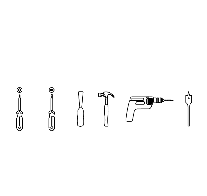
• PHILLIPS SCREWDRIVER
• FLAT HEAD SCREWDRIVER
• CHISEL
• HAMMER
• 1” (25.4 mm) and 2 -1/8” (54 mm) OR 1-1/2” (38 mm) HOLE BORING KIT
• POWER DRILL
• 4 - AA ALKALINE BATTERIES
TOOLS NEEDED FOR NEW INSTALLATION
OPTIONAL OPTIONAL OPTIONAL OPTIONAL OPTIONAL
3
® REGISTERED TRADEMARK OF TAYMOR INDUSTRIES LTD.
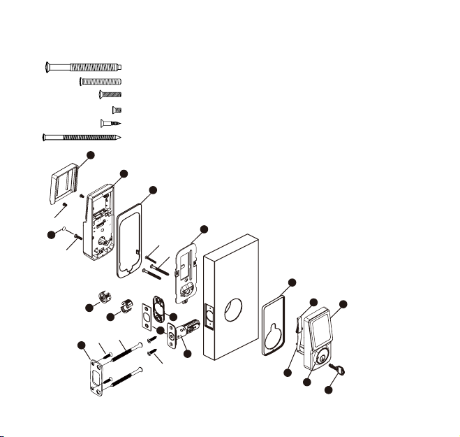
COMPONENTS OF ELECTRONIC
KEYPAD DEADBOLT
A. Key (2)
B. Exterior Assembly
C. Cylinder
D. Tailpiece
E. Power Cable
F. Exterior Gasket (Optional)
G. Mounting Plate
H. Interior Gasket (Optional)
I. Interior Assembly
J. Battery Cover
K. Latch
L. Bottom Plate (Optional)
M. Square or Radius Faceplate
(Optional)
N. Drive-In Collar (not assembled)
O. Drive-In Collar (assembled)
P. High Security Strike Plate
Q. Screw Hole Cover
AA. 2-1/8” Mounting Bolt
BB. 1-1/4” Screw
CC. 13/16” Screw
DD. 5/16” Screw
EE. 3/4” Wood Screw
FF. 3” Wood Screw
QTY.
2
1
1
2
4
2
AA
BB
CC
DD
EE
A
G
F
EB
I
H
J
C
D
K
M
L
N
O
Q
P
FF
EE

TEMPLATE
CENTERLINE
MARK DOOR EDGE APPROXIMATELY
3” TO 6” (75 mm TO 150 mm) ABOVE
THE ENTRY KNOB OR LEVER
® REGISTERED TRADEMARK OF TAYMOR INDUSTRIES LTD.
4
DOOR PREPARATION
1 MARK DOOR WITH TEMPLATE (ATTACHED SEPARATELY)
Note: If replacing an existing lock or installing in a pre-drilled door,
begin with page 9.
a. Use TEMPLATE to mark centerline on door for deadbolt about
3” to 6” (75 mm to 150 mm) above the existing knob or lever.
b. Stand so door swings towards you. Align template on centerline
and fold template as shown.

5
® REGISTERED TRADEMARK OF TAYMOR INDUSTRIES LTD.
DOOR PREPARATION
2 MARK AND DRILL PILOT HOLES
Select backset. Mark and drill pilot holes as shown.
CENTERLINE
BACKSET
DRILL 1/8” (3 mm) PILOT HOLE
1”
(25 mm)
2-1/8” OR 1-1/2”
(54 mm) (38 mm)
DRILL 1/8” (3 mm) PILOT HOLE

® REGISTERED TRADEMARK OF TAYMOR INDUSTRIES LTD.
6
DOOR PREPARATION
3.1 DRILL HOLES
a. Drill a 2-1/8” (54 mm) hole on the door face from both sides to
avoid wood splitting.
b. Use a 2” (51 mm) 6d common nail and press it from inside the
2-1/8” (54 mm) or 1-1/2” (38 mm) hole through the pilot hole to
mark centerlines on jamb exactly opposite center of deadbolt
latch hole.
2-1/8”
(54 mm)

7
® REGISTERED TRADEMARK OF TAYMOR INDUSTRIES LTD.
DOOR PREPARATION
3.2 DRILL HOLES
c. Drill a 1” (25 mm) hole in the door edge for the latch.
d. Use faceplate as a pattern for mortise and pilot holes.
Chisel 5/32” (4 mm) deep. Faceplate should fit flush.
Note: For drive-in latch, simply insert latch.
e. Install as shown for appropriate latch type. Ensure bevel
faces door jamb.
CHISEL 5/32”
(4 mm) DEEP
1”
(25 mm)
FACEPLATE
c.
d.
OUTLINE

DOOR JAMB PREPARATION
® REGISTERED TRADEMARK OF TAYMOR INDUSTRIES LTD.
8
4 PREPARE DOOR JAMB AND INSTALL STRIKE PLATE
Door Jamb hole dimensions
a. 3/32” (2.5 mm)
b. 1” (25 mm)
c. 1-1/8” (28 mm)
3/4” (19 mm) SCREWS
HIGH SECURITY
STRIKE PLATE
3”(76 mm) SCREWS
a.
b.
c.
INSTALLATION
1a LATCH BACKSET ADJUSTMENT
Latch backset adjustment only needs to be made if your door needs
a 2-3/8” (60 mm) backset. Please follow diagrams below as reference.
Skip this if your door has a 2-3/4” (70 mm) backset
9
® REGISTERED TRADEMARK OF TAYMOR INDUSTRIES LTD.
4
® REGISTERED TRADEMARK OF TAYMOR INDUSTRIES LTD.
10
INSTALLATION
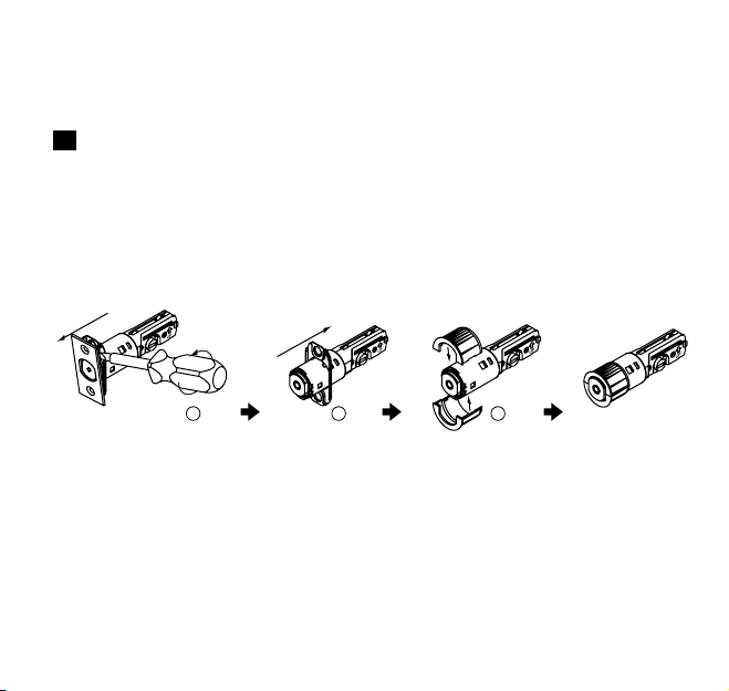
1b DRIVE-IN COLLAR or FACEPLATE ADJUSTMENT
In addition to 2-3/8” (60 mm) or 2-3/4” (70 mm) adjustable backset,
you may change the faceplate to drive-in collar. (If your door is not
a drive-in latch type, please skip this step)
Note: Reverse the above steps if you need to change
the drive-in collar to the faceplate.
COMBINE
REMOVE
REMOVE
1 2 3

11
® REGISTERED TRADEMARK OF TAYMOR INDUSTRIES LTD.
INSTALLATION
2 INSTALL LATCH IN MORTISED AREA OR INSTALL DRIVE-IN LATCH
If the backset of your door is 2-3/8” (60 mm), please install it now.
If your door is set up to use a standard type latch, please install it
with the 3/4” (20 mm) screws that are provided. If you use the
drive-in type latch, please tap it in place.
BACKSET
FACEPLATE
3/4” (20 mm) WOOD SCREWS
OR
DRIVE-IN LATCH TAP
LATCH
FLUSH
WOOD BLOCK
(NOT INCLUDED)
(SEE PAGE 10 BEFORE
INSTALLATION OF
DRIVE-IN LATCH)

INSERT
CYLINDER
TORQUE BLADE
IN HORIZONTAL
POSITION
THE LATCH
BOLT SHOULD
BE IN THE
UNLOCKED
POSITION
THREAD THE CABLE
THROUGH THE HOLE AND
UNDER THE LATCH
® REGISTERED TRADEMARK OF TAYMOR INDUSTRIES LTD.
12
INSTALLATION
FOR INSTALLATION INTO 1-1/2” (38 mm)
BORE HOLE:
1. Remove adapter collar by releasing
cylinder mounting screw and top
mounting post.
2. Once adapter collar is off, reinstall
cylinder mounting screw.
CYLINDER MOUNTING SCREW
ADAPTER COLLAR
3
IMPORTANT

13
® REGISTERED TRADEMARK OF TAYMOR INDUSTRIES LTD.
INSTALLATION
4
THE BULGED PART OF THE MOUNTING
PLATE MUST FACE TOWARD THE DOOR
SLIDE CABLE THROUGH THE
NOTCH OF THE MOUNTING PLATE
® REGISTERED TRADEMARK OF TAYMOR INDUSTRIES LTD.
14
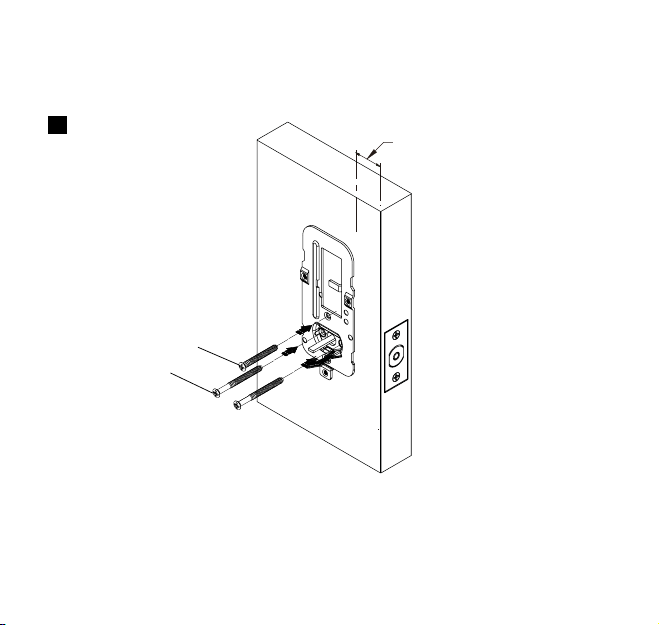
INSTALLATION
5 KEEP PARALLEL TO THE
EDGE OF DOOR
AA
BB
SECURE MOUNTING PLATE WITH 1-1/4” SCREW (1) AND 2-1/8” MOUNTING SCREWS (2)
(1-1/4” SCREW NOT REQUIRED FOR 1-1/2” BORE HOLE)

6 REMOVE THE INTERIOR COVER BY PUSHING THE THUMBTURN
THROUGH
15
® REGISTERED TRADEMARK OF TAYMOR INDUSTRIES LTD.
INSTALLATION
INTERIOR GASKET (OPTIONAL)

INSTALLATION
7
CONNECT THE CABLE INTO
CONNECTOR PORT FIRMLY
® REGISTERED TRADEMARK OF TAYMOR INDUSTRIES LTD.
16
OR

INSTALLATION
8 THE CABLE MUST BE ARRANGED
AS SHOWN IN THE DIAGRAM
17
® REGISTERED TRADEMARK OF TAYMOR INDUSTRIES LTD.
Table of contents
Other Taymor Lock manuals


Popular Lock manuals by other brands


CDVI
CDVI V3ER1248 quick start guide

Gianni Industries
Gianni Industries EB-200N Specifications

CISA
CISA 1A610 Series Instruction for the installation

INOX
INOX ED93F-CVRW Series Instructions for installing

BEST ACCESS SYSTEMS
BEST ACCESS SYSTEMS 62K installation instructions

Simons Voss Technologies
Simons Voss Technologies SmartHandle WP Instruction leaflet