BEST ACCESS SYSTEMS
Indianapolis, Indiana
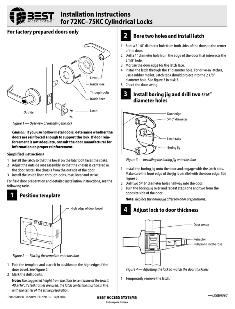
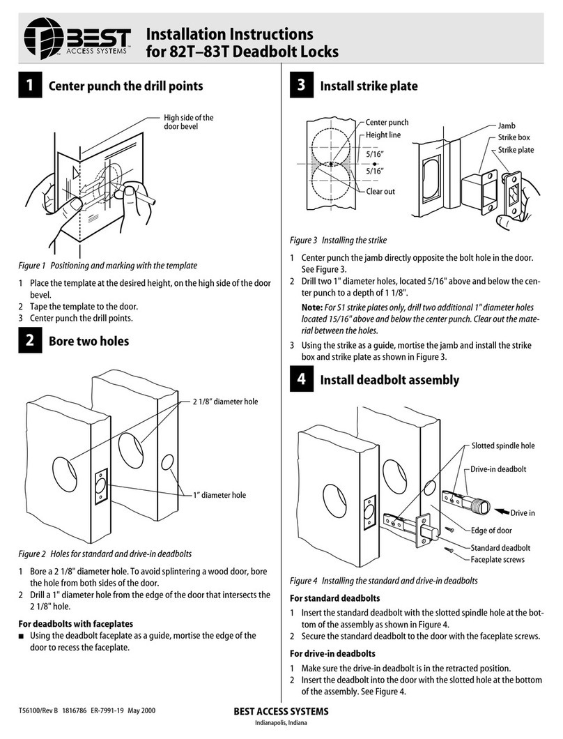
4Adjust to door thickness
■Rotate the outside rose in or out until the
retractor is centered in the door.
5Engage retractor in latch
1 With the latch in place, install the chassis
from outside of the door.
2 Make sure that the latch tabs fit into the
chassis frame and the latch tailpiece fits into
the retractor.
6Install liner and rose
1 Separate the rose and liner (gently pry apart
at the tab slot).
2 Place the liner in position with the tab slot
at the bottom and tighten the through
bolts.
3 Align the rose slot with the liner tab slot at
the bottom and press the rose firmly onto
the liner until flush with the door.
7Install inside knob
1 Align the two lugs (“dimples”) on the knob
shank with the long slot in the sleeve and
slide the knob onto the sleeve.
2 Make sure that the knob keeper snaps into
place.
3 Test both knobs for functionality.
8Install strike plate
1 Mortise the door jamb to fit the strike box
and strike plate. Make sure to align the
strike plate and latchbolt centers.
Caution: The deadlocking plunger of the
latchbolt must not enter the strike plate
opening. The plunger deadlocks the
latchbolt and prevents forcing the latch
when the door is closed. A gap of more
than 1/8” may reduce security and/or
cause improper operation of the latch-
bolt.
2 Insert the strike box and secure the strike
plate with the screws provided.
9Check handing
Note: When BEST 6K locks are properly
installed, the figure-8 hole must be in the
upper half of the knob. If it is not, change the
hand of the lock.
To change the hand of the lock
1 Remove the core and throw member (if
already installed). See Figure 11.
2 Rotate the knob face one-half turn so that
the figure-8 is in the upper half of the knob.
10 Install core
For ‘R’ function locks only
■Simulating the throw member, insert a
screwdriver into the figure-8 opening and
turn the locking mechanism counterclock-
wise as far as it will go before installing the
core.
For all functions (including ‘R’ function)
For 6-pin core users only: Slide the spacer
— supplied with your 6-pin cores — over
the 7-pin throw member.
Note: If you have ordered 6-pin cores, you
will get one spacer per core with your order.
Spacers are not supplied with locks.
1 Insert the throw member (or throw member
and spacer) into the back of the core.
2 Insert the control key into the core and turn
the key 15 degrees clockwise.
3 Insert the core and throw member into the
knob with the control key as shown in
Figure 11.
4 Turn the key 15 degrees counterclockwise
and remove the key.
Figure 5 — Centering the retractor
Figure 6 — Engaging the latch and retractor
Figure 7 — Installing the rose over the liner
Retractor
Outside rose
Latch tailpiece
Latch tabs
Chassis frame
Retractor
Rose slot
Through bolts
Tab slot
Liner
Figure 8 — Aligning and installing the inside
knob
Figure 9 — Installing the strike box and plate
Lugs
Slot
Sleeve
Door jamb
Strike box
Strike plate
Figure 10 — Turning the knob face to correct
the handing of the lock
Figure 11 — Installing the core
Incorrect Correct
Knob face
BEST
BEST
Core
Throw member
Control key
T56061/Rev A 1797989 ER-7991-19 May 2003
