Projoy Electric PEFS-PL80P-11 User manual

www.projoy-electric.com
Installation
Guide
Panel-level Rapid Shutdown(PLC)

www.projoy-electric.com
Panel-level Rapid Shutdown(PLC)
CONTENT
1 Safety Precautions2 Safety instructions and regulations
1.1 Scope of Application
1.2 Safety Instructions
1.3 Target Group
2 Preparation
2.1 Safety Instructions
2.2 Explanations of Symbols
3 Product Information
3.1 Application Scope of Products
3.2 Specification for Product Model
3.3 System Diagram
3.4 Overview and Dimensions of products
3.5 Datasheet
4 Instructions for installation
4.1 Safety Instructions
4.2 Pre-installation Check
4.3 Installation of PEFS-PL80P-11/21
4.4 Installation of PEFS-PLC-CN
4.5 Start the PVRSS system
5 System Test and Troubleshooting
5.1 System test
5.1.1 Function test
5.1.2 Maintain test
5.2 Troubleshooting
6. Recycling and Disposal
7. Guarantee Service
8. Contact Projoy
1
1
1
1
2
2
3
4
4
4
4
5
6
7
7
7
7
9
11
12
12
12
12
12
13
13
13

1 Safety Precautions
1.1 Scope of Application
1.2 Safety Instructions
1.3 Target Group
This User Manual describes instructions and detailed procedures for installing, operating, maintaining, and troubleshooting
of the following Projoy Panel-level Rapid Shutdown Equipment:
PEFS-PL80P-11 PEFS-PL80P-21 PEFS-PLC-CN
Please keep this manual all time available in case of emergency.
Only qualified electricians who have read and fully understood all safety regulations contained in this manual can install,
maintain and repair the Panel-level rapid shutdown equipment.
www.projoy-electric.com1
DANGER
·DANGER indicates a hazardous situation which, if not avoided,
will result in death or
serious injury.
WARNING
·WARNING indicates a hazardous situation which, if not avoided, can result in death or
serious injury or moderate injury.
CAUTION
·CAUTION indicates a hazardous condition which, if not avoided, can result in minor or
moderate injury.
NOTICE
·NOTICE indicates a situation that can result in potential damage, if not avoided.
Panel-level Rapid Shutdown(PLC)

2.1 Safety Instructions
• Do not disconnect PEFS-PL while the PVRSS is working. There is possibility of dying due to electrical
shock and high voltage.
• To prevent risk of electric shock during installation and maintenance, please make sure that PEFS-PLC-CN
or any other control unit, such as the DC switch of inverter, are turned off.
•The PSFS-PL80P-11 or PEFS-PL80P-21 will become hot during operation. Please do not touch the surface
during or shortly after operation.
•Risk of damage due to improper modifications.
•All electrical installations must be done in accordance with the National Wiring Rules of Standard and
local code.
•The installation, service, recycling and disposal of the PVRSS must be performed by qualified personnel
only in compliance with national and local standards and regulations.
•Any unauthorized actions including modification of product functionality of any form may cause lethal
hazard to the operator, third parties, the units or their property. Projoy is not responsible for the loss and
these warranty claims.
•While PSFS-PL80P-11 or PEFS-PL80P-21 are used without PEFS-PLC-CN, be sure that this photovoltaic rapid
shutdown equipment (PVRSE) does not perform all of the functions of a complete photovoltaic rapid
shutdown system (PVRSS). This PVRSE must be installed with other equipment to form a complete
PVRSS that meets the requirements of NEC (NFPA 70) section 690.12 for controlled conductors outside
the array. Other equipment installed in or on this PV system may adversely affect the operation of the
PVRSS. It is the responsibility of the installer to ensure that the completed PV system meets the rapid
shut down functional requirements. This equipment must be installed according to the manufacturer’s
installation instructions.
•While PSFS-PL80P-11 or PEFS-PL80P-21 are used with PEFS-PLC-CN, be sure that this photovoltaic rapid
shutdown system (PVRSS) incorporates one or more pieces of equipment that exercise the rapid
shutdown control of PV system conductors required by section 690.12 of the NEC (NFPA 70). other
equipment installed in or on this PV system may adversely affect the operation of this PVRSS. it is the
responsibility of the installer to ensure that the completed PV system meets the applicable rapid shut
down functional requirements. this equipment must be installed according to the manufacturer’s
installation instructions.
DANGER
WARNING
CAUTION
www.projoy-electric.com 2
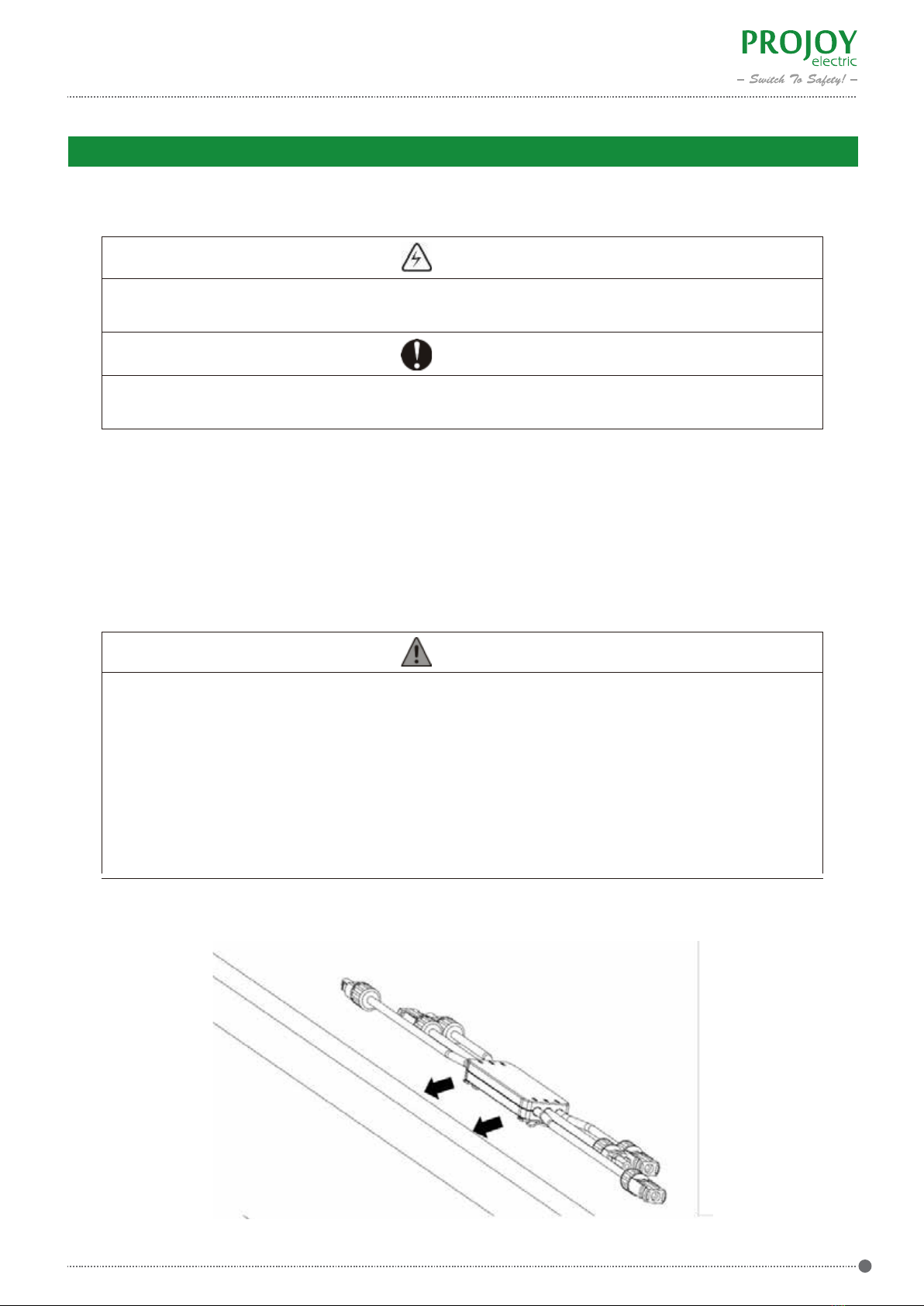
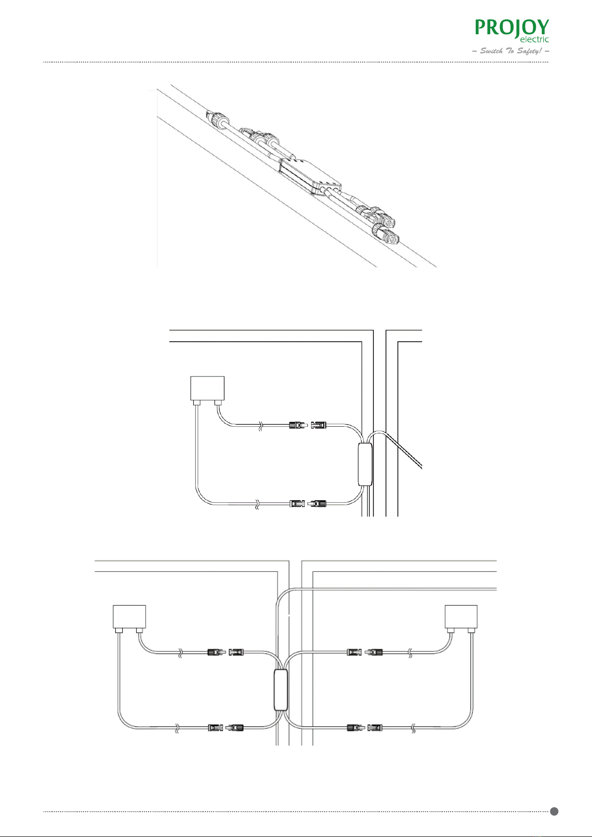
2 Preparation
Panel-level Rapid Shutdown(PLC)

www.projoy-electric.com 3
2.2 Explanations of Symbols
Symbol Description
Danger of high electrical voltage
Read the User Manual First
Recycling and Disposal
This device SHALL NOT be disposed of in residential waste.
Please read the User Manual first before the installation and operation.
This device is connected in series to the solar inverter, thus all work to the PVRSE
shall only be carried out by qualified personnel.
Danger of hot surface
The components inside the PVRSE will release a lot of heat during operation.
Do not touch the surface during operating.
RoSH RoSH Directive
This device complies the RoSH Directive.
Panel-level Rapid Shutdown(PLC)

PEFS - PL80P-11
PEFS: RSD represents for Rapid Shutdown.
PL: Panel-level.
80: Voltage parameter.
P: Power carrier communication.
1/2: Input port.
1/2: Product Iteration.
www.projoy-electric.com 4
3.1 Application Scope of Products
3.2 Specification for Product Model
3.3 System Diagram
3 Product Information
Figure 3.1 System Diagram (PEFS-PL80P-11 and PEFS-PLC-CN)
Figure 3.2 System Diagram (PEFS-PL80P-21 and PEFS-PLC-CN)
Panel-level Rapid Shutdown(PLC)
PLC Box Inverter
Grid
≤80V ≤80V ≤80V
……
DC+
DC-
PEFS-PL PEFS-PL PEFS-PL
DC+
PLC Box
Inverter
Grid
≤80V ≤80V ≤80V ≤80V ≤80V ≤80V
……
DC+
DC-
PEFS-PL PEFS-PL PEFS-PL
DC+

www.projoy-electric.com5
3.4 Overview and Dimensions of products
The dimensions of PEFS-PL80P-11 and PEFS-PL80P-21 are shown in Figure 3.3.
The dimensions of PEFS-PLC-CN are shown in Figure 3.4.
Figure 3.3 Dimensions of PEFS-PL80P-11 and PEFS-PL80P-21
Figure 3.4 Dimensions of PEFS-PLC-CN
Panel-level Rapid Shutdown(PLC)
(Unit: mm)
(Unit: mm)

www.projoy-electric.com 6
3.5 Datasheet
MODEL
Max. Input Current [A]
Input Vmax PV [Vdc]
Output Vmax PV [Vdc]
Max. System Voltage [V]
Isc PV (absolute Max.) [A]
Rapid Shutdown Time Limit [s]
Tripping
Operating Temperature [℃]
Ingress Protection
Humidity
Communication
Overvoltage Category
Mounting
Dimension W*H*D [mm]
MODEL
Operating AC Voltage Range
Norminal Frequency
Power Consumption
DC Input Strings
Operating Temperature Range
Protection Class
Communication
Mounting
Connector
Dimension(W*H*D)
Weight
PEFS-PLC-CN
100 V-240 V
50/60 Hz
<1W
4 Strings
-30℃ to +55℃
IP65
PLC
Wall Mounted
MC4 Compatible (DC) , Plug in Connector (AC)
210mm*174mm*101mm
1800g
PEFS-PL80P-11
20
80
80
1500
20
PEFS-PL80P-21
20/20
80/80
160
1500
20
10
PLC Signal
-40 to +80
Type 6P
0 ‒ 90%
PLC
II
Clip
120 * 44 * 20
Panel-level Rapid Shutdown(PLC)

Although Projoy’s products have surpassed stringent testing and are checked before they leave the factory, it is uncertain
that the products may suffer damages during transportation. Please check the package for any obvious signs of damage,
and if such evidence is present, do not open the package and contact your dealer as soon as possible.
•While PEFS-PL80P-11/21 are used without PEFS-PLC-CN, be sure that this photovoltaic rapid shutdown
equipment (PVRSE) does not perform all of the functions of a complete photovoltaic rapid shutdown
system (PVRSS). This PVRSE must be installed with other equipment to form a complete PVRSS that meets
the requirements of NEC (NFPA 70) section 690.12 for controlled conductors outside the array. Other
equipment installed in or on this PV system may adversely affect the operation of the PVRSS. It is the
responsibility of the installer to ensure that the completed PV system meets the rapid shut down
functional requirements. This equipment must be installed according to the manufacturer’s installation
instructions.
www.projoy-electric.com7
DANGER
NOTICE
WARNING
• To prevent risk of electric shock during installation and maintenance, please make sure that PEFS-PC or
any other control unit, such as the DC switch of inverter, are turned off.
•All electrical installations must be done in accordance with the National Wiring Rules of Standard and
local code.
1) Fix the rapid shutdown device (PEFS-PL80P-11/21) on the frame of solar module.
4 Instructions for installation
4.1 Safety Instructions
4.2 Pre-installation Check
4.3 Installation of PEFS-PL80P-11/21
Panel-level Rapid Shutdown(PLC)

www.projoy-electric.com 8
Figure 4.1&4.2 Fixing the Rapid Shutdown Device
Figure 4.3 Connecting PEFS-PL80P-11 and solar module
Figure 4.4 Connecting PEFS-PL80P-21 and solar modules
2) Connect the input of rapid shutdown device to the solar module.
Panel-level Rapid Shutdown(PLC)

4) While PEFS-PL80P-21 are used without PEFS-PLC-CN, connect each string of the rapid shutdown devices to the
solar inverter.
Push out the bracket of the rapid shutdown controller. Fix the rapid shutdown controller (PEFS-PLC-CN) on the wall.
•While PEFS-PL80P-21 are used with PEFS-PLC-CN, be sure that this photovoltaic rapid shutdown system
(PVRSS) incorporates one or more pieces of equipment that exercise the rapid shutdown control of PV
system conductors required by section 690.12 of the NEC (NFPA 70). other equipment installed in or on
this PV system may adversely affect the operation of this PVRSS. it is the responsibility of the installer to
ensure that the completed PV system meets the applicable rapid shut down functional requirements. this
equipment must be installed according to the manufacturer’s installation instructions.
•Installers should determine the installation location of rapid shutdown controller according to local
regulations.
www.projoy-electric.com9
WARNING
3) Connect the outputs of all the rapid shutdown devices one after another.
Figure 4.5 Connecting Rapid Shutdown Device in Series
4.4 Installation of PEFS-PC
Panel-level Rapid Shutdown(PLC)

www.projoy-electric.com 10
2) Plug each string of rapid shutdown devices to the rapid shutdown controller. Then plug each output cable to the
solar inverter.
Figure 4.6&4.7 Fixing the Rapid Shutdown Controller
Figure 4.8 Wiring diagram of control box
Panel-level Rapid Shutdown(PLC)
+1
- 1
+N
+N
N=4,N=6,N=8,N=10,N=20
Solar Inverter
PLC Transmitter
S1
SN

Turn on the power source of rapid shutdown controller. The rapid shutdown control system will start to work.
The status of lights is shown as below:
Firefighters can push the button to cut off all the solar modules while in the emergency.
After the emergency, users can rotate the button and the solar module will work again.
Rapid shutdown controller is powered
on and send signals to the rapid
shutdown devices in each string.The
status of lights is shown as below:
Rapid shutdown controller is powered
off or stop sending signals to the rapid
shutdown devices in each string.
www.projoy-electric.com 11
On
Power
(Red)
Off
Figure 4.10 Connecting PEFS-PL80P-21 and solar modules
Table 4.1 Light Status
4.5 Start the PVRSS system
Panel-level Rapid Shutdown(PLC)
3) Multiple control boxes can be connected in series and can be controlled by a single master control box.
Figure 4.9 Connection diagram of multiple control boxes
4) Put the warning label in the PV system as required in the section 690.56(C) of NEC (NFPA70).

www.projoy-electric.com12
System Work Normally
System Work Abnormally
System Voltage = 0.9 V * Quantities of PEFS-PL80P-11 or
System Voltage = 1.75 V * Quantities of PEFS-PL80P-21
System Voltage < 0.9 V * Quantities of PEFS-PL80P-11 or
System Voltage < 1.75 V * Quantities of PEFS-PL80P-21
Status light is always off.
PVRSS doesn’t work.
1) Check if the button of controller is turned to off;
2) Check if the AC power supply is normal;
3) Check if the AC voltage is over the operating voltage rang;
4) Contact Projoy.
1) Check if the button of controller is turned to off;
2) Check if the AC power supply is normal;
3) Check if the AC voltage is over the operating voltage rang;
4) Contact Projoy.
1) Test the output voltage of each rapid shutdown device. If the
1) Test the voltage of DC cable. If the voltage of DC cable is zero,
check the connection of DC cable.
2) If the voltage of DC cable is normal as described in §5.1.2,
there is something wrong in the DC input of inverter. Contact
the supplier of inverter.
3) Contact Projoy.
Status light is on.
DC voltage of inverter is 0V.
PVRSS doesn’t work.
Status light is on.
DC voltage of inverter is 0V.
PVRSS doesn’t work.
Status light is on.
DescriptionTroubleshooting
Table 5.1 System test
Please do the function test regularly.
1) Push the button of rapid shutdown controller. The status of light will be off. Check the solar inverter. The DC current will
be cut off and the DC voltage will be lower than 30V in 30 seconds.
2) Rotate the button of rapid shutdown controller. The status of light will be on. The solar will start to work again.
When the PEFS-PLC-CN stops working, the PEFS-PL80P-11 will have a continuous 0.9 V output and the PEFS-PL80P-21
will have a continuous 1.75 V output.
1) Push the button and stop the PEFS-PLC-CN.
2) Separate the DC cable and rapid shutdown controller. Test the voltage of each DC cable.
5.1 System test
5.1.1 Function test
5.1.2 Maintain test
5.2 Troubleshooting
5 System Test and Troubleshooting
Panel-level Rapid Shutdown(PLC)

output voltage is not 0.9V or 1.8V. Replace the rapid shutdown device.
2) Contact Projoy.
PVRSS work well.
DC voltage of inverter is
abnormal (§5.1.2).
www.projoy-electric.com 13
Projoy Electric Co., Ltd.
Tell: +86-512-6878 6489
Web: https://en.projoy-electric.com/
Add: 2nd Floor, Building 3, No. 2266, Taiyang Road, Xiangcheng District, Suzhou
8 Contact us
Table 5.2 Troubleshooting
6. Recycling and Disposal
7. Guarantee Service
This device should not be disposed as residential waste. A rapid shutdown device or controller that has reached
the end of its life and is not required is to be returned to your dealer or you must find an approved collection and
recycling facility in your area.
Within warranty period of the products, the invoice and date of purchase are required for the service. Besides, the
trademark on the product should be clearly visible, otherwise warranty is not available.
The product warranty covers all damage caused by design or production. However, the followings are not covered:
* Beyond the warranty period;
* No valid warranty card and product serial number;
* Damage in transportation;
* Incorrect use, operation and modification;
* Operation in very harsh environment not as described in this manual;
* Out of the scope of installation and use specified in relevant international standards;
* Damage caused by abnormal natural environment.
Panel-level Rapid Shutdown(PLC)
Other manuals for PEFS-PL80P-11
1
This manual suits for next models
2
Table of contents
Other Projoy Electric Inverter manuals
Popular Inverter manuals by other brands

Omron
Omron SYSDRIVE MX2 SERIES datasheet

TRU Components
TRU Components 2315349 operating instructions

Westerbeke
Westerbeke 4.5BCG Operator's manual

MAER IDROPULITRICI
MAER IDROPULITRICI AVANT 120/11 Instructions for installation and use

Carbest
Carbest 82282 instruction manual

Victron energy
Victron energy PIN121800300 manual