TBB eRay IH Series User manual
eRay Pure Sine Wave Inverter Manual
WARNING: HIGH VOLTAGE INSIDE
CAUTION: THE DC FUSE MUST HAVE BEENTURNED OFF BEFORE SERVICING
MADE IN CHINA

eRay Pure Sine Wave Inverter Manual
Disclaimer
Unless specially agreed in writing, TBB Power Co., Ltd
Take no warranty as to the accuracy, sufficiency of suitability of any technical or other information
provided in this manual or other documentation.
Assumes no responsibility or liability for loss or damage, whether direct, indirect, consequential or
incidental, which might arise out of the use of such information.
TBB offer standard warranty with its products, taking no responsibility for direct or indirect loss due
to equipment failure.
About TBB
TBB Power is a dedicated designer and manufacturer of sophisticated and environmentally rugged
power electronic equipment.
We are offering a wide range of power conversion product from battery charger, standalone inverter,
inverter charger combination and solar charge controller.
We ensure consistent product quality by subjecting every product to strictly choice of superior
quality components, rigorous testing and burn-in throughout the production process. TBB Power is
certified by TUV in accordance with ISO9001 and can be your reliable power solution provider.
About this Manual
This manual describes our product features and provides procedure of installations. This manual is
for anyone intending to install our equipment.

eRay Pure Sine Wave Inverter Manual
Contents
1. General Safety Instruction..........................................................................................................................1
1.1 Safety Instruction............................................................................................................................... 1
1.2 General Precaution........................................................................................................................... 1
1.3 Precaution regarding battery operation..........................................................................................1
2. Introduction................................................................................................................................................... 2
3. Structure........................................................................................................................................................3
3.1 Product drawing................................................................................................................................. 3
3.2 Control panel...................................................................................................................................... 5
3.3 Available sockets type.......................................................................................................................7
4. Configuration................................................................................................................................................ 8
4.1 Set the AC output voltage and frequency...................................................................................... 8
4.2 Power saving setting......................................................................................................................... 8
5. Installation...................................................................................................................................................10
5.1 Material list....................................................................................................................................... 10
5.2 Location.............................................................................................................................................10
5.3 Wiring + Fuserecommendation..................................................................................................... 10
5.4 Installation and Connection............................................................................................................11
5.4.1 Fix the equipment.................................................................................................................11
5.4.2 Connecting the cable........................................................................................................... 11
6. Operation.................................................................................................................................................... 15
6.1 Double Checking............................................................................................................................. 15
6.2 Inverter operation............................................................................................................................ 15
6.3 LED indicator status........................................................................................................................15
7.Trouble shooting......................................................................................................................................... 17
8.Specification................................................................................................................................................ 19

eRay Pure Sine Wave Inverter Manual
1
1. General Safety Instruction
1.1 Safety Instruction
As dangerous voltages and high temperature exist within the eRay inverter, only qualified and
authorized maintenance personnel are permitted to open and repair it.
This manual contains information concerning the installation and operation of the eRay inverter. All
relevant parts of the manual should be read prior to commencing the installation. Please follow the
local stipulation meantime.
Any operation against safety requirement or against design, manufacture, safety standard, and are
out of the manufacturer warranty.
1.2 General Precaution
1) Do not expose to dust, rain, snow or liquids of any type,it is designed for indoor use. DO NOT
block off ventilation, otherwise the INVERTER would be overheating.
2) To avoid fire and electric shock,make sure all cables selected with right gauge and being
connected well. Smaller diameter and broken cable are not allowed to use.
3) Please do not put any inflammable goods near to inverter.
4) Never place unit directly above batteries, gases from a battery will corrode and damage
inverter/charger.
5) Do not place battery over the inverter.
1.3 Precaution regarding battery operation
1) Use plenty of fresh water to clean in case battery acid contacts skin, clothing, or eyes and
consult with doctor as soon as possible.
2) The battery may generate flammable gas during charging. NEVER smoke or allow a spark or
flame in vicinity of a battery.
3) Do not put the metal tool on the battery, spark and short circuit might lead to explosion.
4) Remove all personal metal items such as rings, bracelets, necklaces, and watches while
working with batteries. Batteries can cause short-circuit current high enough to make metal
melt, and could cause severe burns.

eRay Pure Sine Wave Inverter Manual
2
2. Introduction
eRay inverter could supply a steady pure sine wave AC to various load on board, such as coffee
machine, microwave, hairdryer or sensitive electronics. It could bring home comfort and
convenience for your life or work on board, either motor home or utility vehicle.
Pure sine wave output
High frequency design featuring compact and light weight
200% surge capability for 1s
High efficiency up to 90%
Low static consumption power
Power save mode through dip switch
Thermal control fan
With built in USB charger, 5V/2A
Output voltage and frequency settable by dip switch
Complete protection with reverse polarity protection
DC input under/over voltage protection
Over temperature protection
Over load and short circuit protection
DC input reverse polarity protection by fuse
Optional remote control available
RS485 communication

eRay Pure Sine Wave Inverter Manual
3
3. Structure
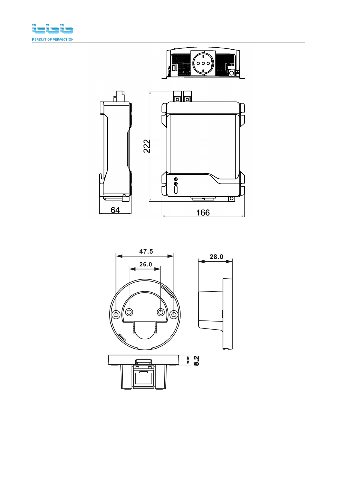
3.1 Product drawing
Figure 3-1 1500/2000W
Figure 3-2 700/1000W
eRay Pure Sine Wave Inverter Manual
4
Figure 3-3 400W
Figure 3-4 Optional remote control RIH
eRay Pure Sine Wave Inverter Manual
5
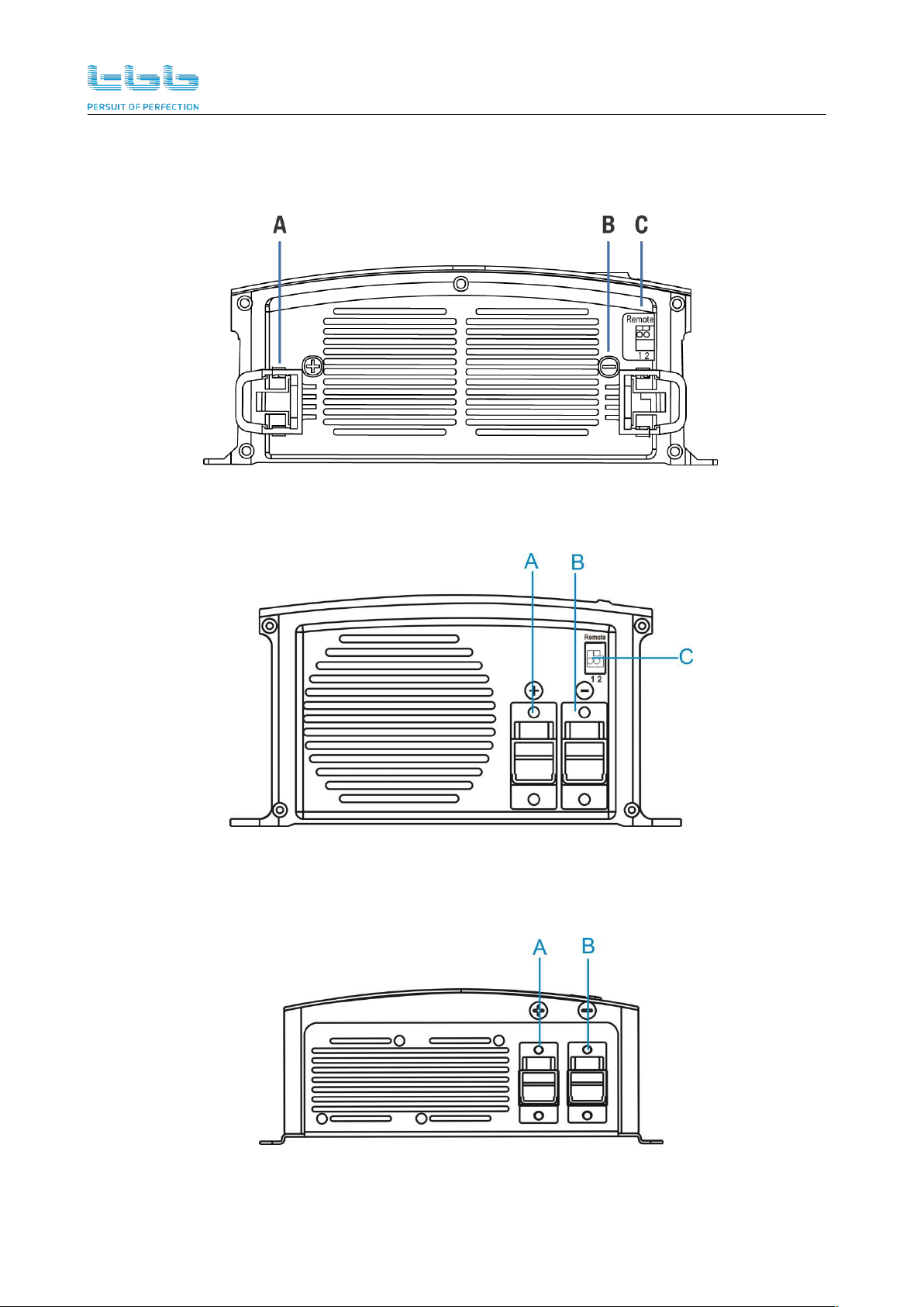
3.2 Control panel
Rear panel
Figure 3-5 1500/2000W
Figure 3-6 700/1000W
Figure 3-7 400W

eRay Pure Sine Wave Inverter Manual
6
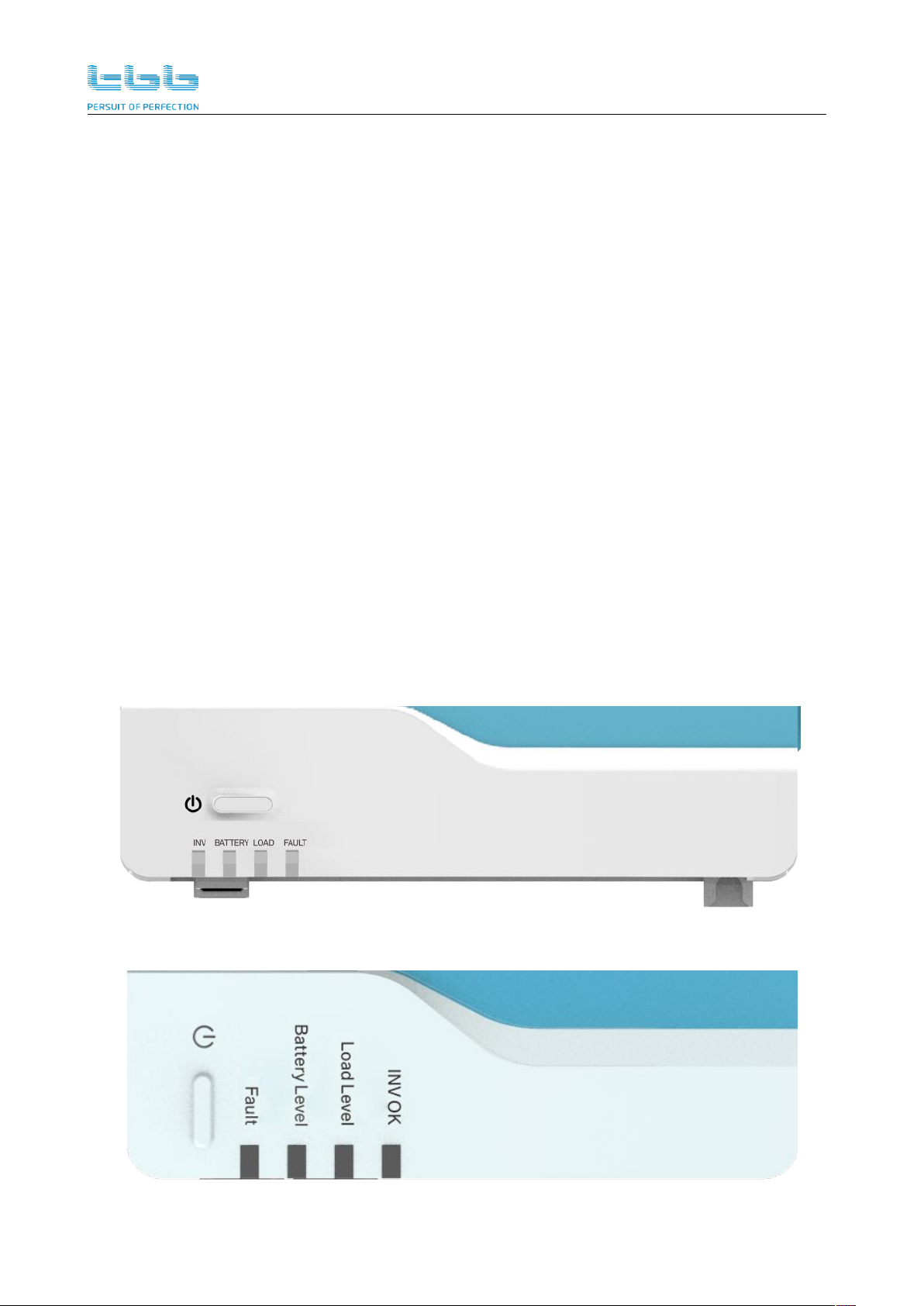
Front panel
Figure 3-8 1500/2000W
Figure 3-9 700/1000W
Figure 3-10 400W
eRay Pure Sine Wave Inverter Manual
7
Table 3-1 Port definitions
A
+
DC input +
H
S1
Dip switch for voltage and
frequency setting
B
-
DC input -
I
LED
LED indicator
C
Remote
Dry contact input
J
ON/OFF
D
Remote
Reserved for remote
control
K
AC Output 1
AC output socket
E
RS485
RS485 port
L
AC Output 2
AC output socket
F
USB charger
P
GND
G
S2
Dip switch for power
saving mode
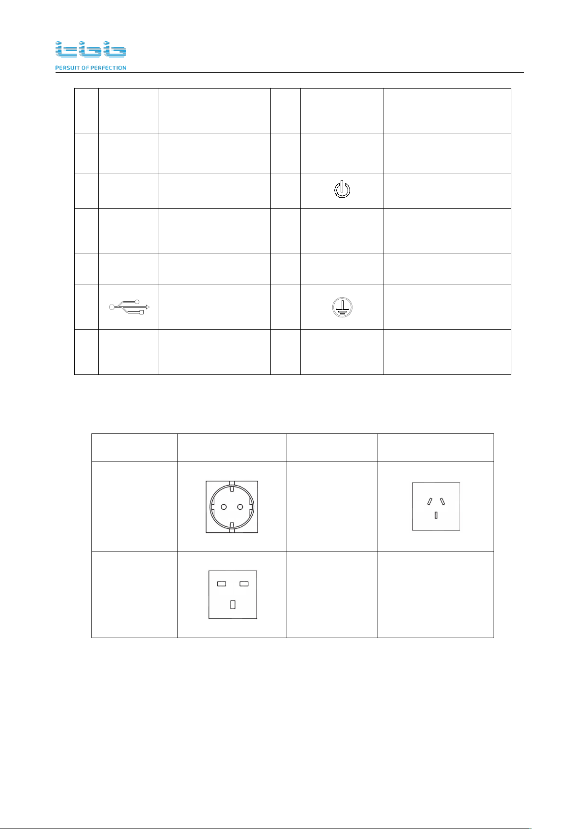
3.3 Available sockets type
Table 3-2 Available sockets type
Socket type
Picture
Socket type
Picture
European type
Australian type
UK type

eRay Pure Sine Wave Inverter Manual
8
4. Configuration
The dip switch setting function is only available for 1500/2000W model.
Please do the correct configuration for voltage and frequency by dip switch S1 before installing the
inverter.The default factory setting is 230VAC 50Hz.
Also the user can set the power saving mode by dip switch S2.The default factory setting of power
saving is OFF.
Figure 4-1 Dip switch
4.1 Set the AC output voltage and frequency
Please refer the below table for the dip switch setting.
Table 4-1 Dip switch setting
Frequency
Output voltage
S1-1=0
50Hz
S1-2=0
S1-3=0
220VAC
S1-1=1
60Hz
S1-2=1
S1-3=0
230VAC
Kindly be noticed that the frequency
setting only is affective after rebooting.
S1-2=0
S1-3=1
240VAC
S1-2=1
S1-3=1
250VAC
4.2 Power saving setting
Power saving mode is enable by S2-1 Dip switch on the front panel. Please refer the below table.

eRay Pure Sine Wave Inverter Manual
9
Table 4-2 Enable setting
Dip switch status
Function
S2-1 = 0
Disable the power saving mode
S2-1 = 1
Enable the power saving mode
Power saving threshold setting value is adjustable by Dip switch S2-2/3/4. Please refer the below
table
When the load is less than the power-saving threshold setting value, the inverter automatically
enters the power saving mode to reduce the static power consumption, thereby saving battery
power.
When the inverter is in power saving, the “inverter” indicator is flashing.
During the period when the inverter is in power saving status, there is a discontinuous output
every 6secs to detect the load status. Please adjust the threshold value if the loads are
powered on shortly by the output.
There is a small gap between the threshold of entering and exiting the power saving mode.
That is to avoid the frequent switch when the load power is close to the threshold value
because of the detecting deviation.
Table 4-3Threshold setting
Dip switch status
Enter threshold
Exit threshold
S2-2
S2-3
S2-4
0
0
0
20W
25W
1
0
0
30W
35W
0
1
0
40W
45W
1
1
0
50W
55W
0
0
1
60W
65W
1
0
1
70W
75W
0
1
1
80W
85W
1
1
1
90W
95W

eRay Pure Sine Wave Inverter Manual
10
5. Installation
5.1 Material list
The unit is packed with following materials. Please confirm the series number on inverter is same to
that on outer carton
eRay pure sine wave inverter
User’s manual
DC terminal plastic cover (Black*1 and Red*1)
5.2 Location
Please install the equipment in a location of Dry, Clean, Cool with good ventilation.
Working temperature:-20~40℃
Storage temperature:-30-70℃
Relative Humidity:10%-95%,non-condensing
Cooling: Forced air
5.3 Wiring + Fuse recommendation
Please find the following minimum wire size. In case of DC cable longer than 3m, please increase
the cross section of cable to reduce the loss.
We recommend connecting a DC fuse corresponding to the conductor between battery and inverter,
which will offer protection to the battery cable. Please refer to following chart of our
recommendations.
On the AC output side, we recommend connecting the output from the inverter to Circuit Breaker.
Model
DC Cable size
Fuse size
12VDC
24VDC
12VDC
24VDC
IH400
10mm²
6mm²
50A
30A
IH700
16mm²
10mm²
100A
60A
IH1000
25mm²
16mm²
160A
80A
IH1500
50mm²
25mm²
200A
125A
IH2000
50mm²
25mm²
250A
150A
eRay Pure Sine Wave Inverter Manual
11
5.4 Installation and Connection
For the user operation safety, cut off the power before installation
5.4.1 Fix the equipment
Basically, eRay inverter could be installed either vertically on wall or horizontally on floor.
Please choose a flat surface and with M6 to fix the unit securely
In mobile application, please keep the vibration as small as possible
5.4.2 Connecting the cable
Please make sure the inverter is turned off before connection.
Otherwise, high voltage could be present.
Please double check battery voltage match the model you are
going to install, the wrong battery could destroy equipment and is
out of warranty.
Please double confirm the polarity of DC input. Reverse polarity
could cause permanent damage on equipment and it is out of
warranty.
Please ensure that the protective grounding of the chassis is
connected to the ground or the chassis of the vehicle when using
this machine on the application platform of vehicles and ships.

eRay Pure Sine Wave Inverter Manual
12
Connecting to earth
At the bottom of the enclosure, there is a ground terminal. Please connect it with EARTH or vehicle
chassis via an 8# AWG wire.
Figure 5-1 Connecting diagram of the ground terminal
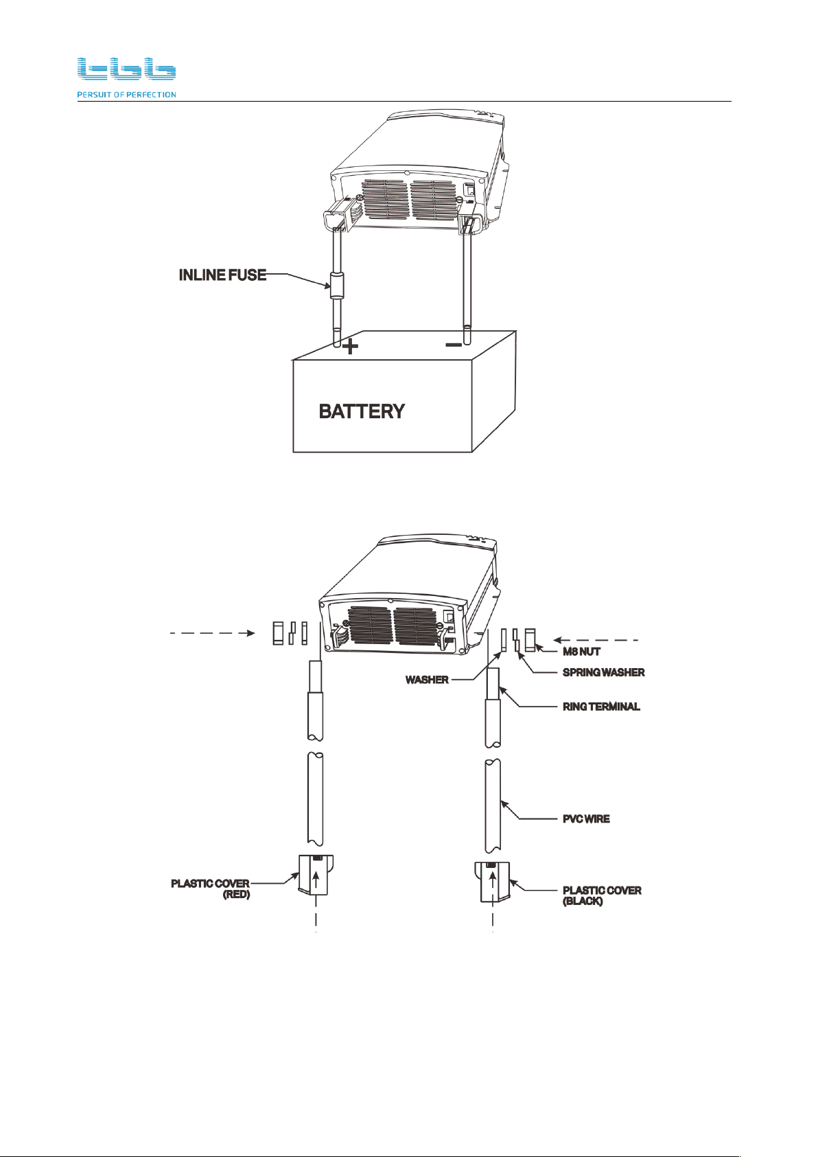
Connecting to battery
The installation of a fuse must be on a positive cable. Failure to place a fuse on positive
cable between the inverter and battery may cause damage to the inverter and it is out of
warranty.
Ensure all the battery cables are tight (torque to 12Nm). Loose connections may cause
overheat and fire.
Choose the right cable size (refer to 5.3 for details) and follow polarity guide marked on the
panel.
Pull the positive DC cable through the red plastic cover and negative DC cable through the
black plastic cover.
Insert the cables to the DC input terminals on the rear panel of the inverter. The red terminal is
represents positive (+) and black terminal represents negative (-).
Secure the DC cable on DC input + and DC input - terminals respectively making sure it is tightly
screwed.
Cover the red and black plastic caps on DC + and DC - terminals respectively.
eRay Pure Sine Wave Inverter Manual
13
Figure 5-2 Connecting diagram of the battery cables
Figure 5-3 Connecting diagram of the DC input terminals
eRay Pure Sine Wave Inverter Manual
14
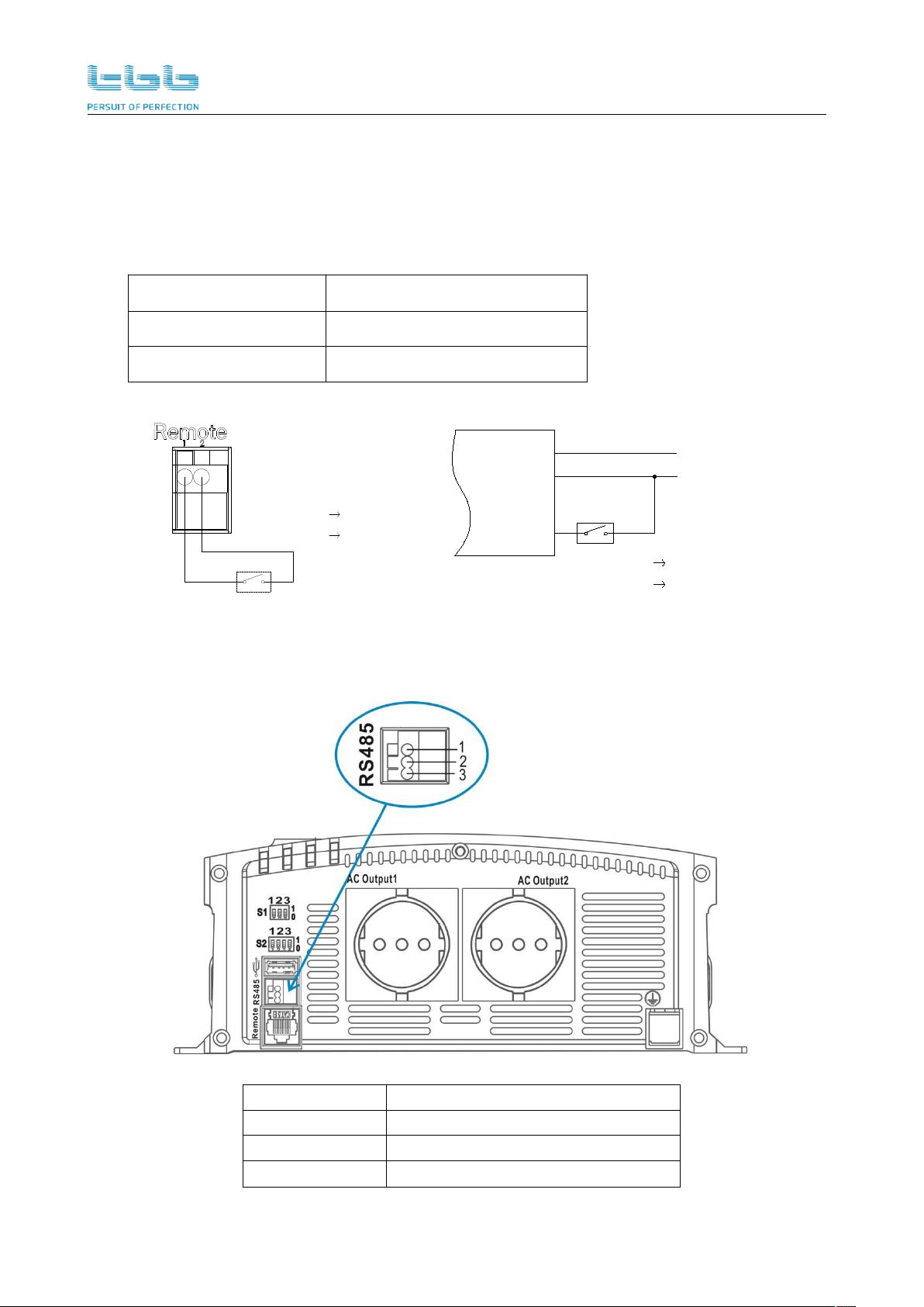
Connecting dry contact input
1) You can use dry contact supplied to switch on/off the inverter through ignition.
2) At anytime, please use only one of them to control the inverter on/off, either main switch or dry
contact.
3) Please find the following two recommended wiring for dry contact input
Item
Description
Remote –pin 1
Remote- pin 2
BAT+
Notice:
ON:INV ON
OFF:INV OFF
BAT+
BAT-
ON:INV ON
OFF:INV OFF
Remote
1 2
Connecting RS485
Serial port monitoring and control through computer interface.
Port
Definition
1
RS485 B-
2
GND
3
RS485 A+
eRay Pure Sine Wave Inverter Manual
15
6. Operation
6.1 Double Checking
Check the DC input voltage of this inverter is same to your battery nominal voltage. NEVER try
to connect different DC input to inverter.
Inspect the right polarity of DC on service battery; otherwise the unit cannot be powered ON.
Please check if you connect the Negative terminal of starter battery to the DC – terminal of
inverter.
Inspect AC output is correct; make sure unit is no short circuit.
6.2 Inverter operation
Press shortly the ON/OFF switch on the front panel to turn the inverter power on. After that the “INV”
and “BATTERY” LED indicators are illuminated, and then the inverter is ready to deliver AC power
to the loads.
The ON/OFF switch, dry contact input and optional remote control works independently. It means if
you use one group switch to power on the inverter, you can only use the same group to power off.
6.3 LED indicator status
Figure 6-1 LED indicator of IH2000/IH1500
Figure 6-2 LED indicator of IH1000/IH700
eRay Pure Sine Wave Inverter Manual
16
Table 6-1 LED directive function
LED indicator
Description
INV/
INV OK
Indicates status of inverter
BATTERY/
Battery Level
Indicates battery level
LOAD/
Load Level
Indicates load level
FAULT
fault status
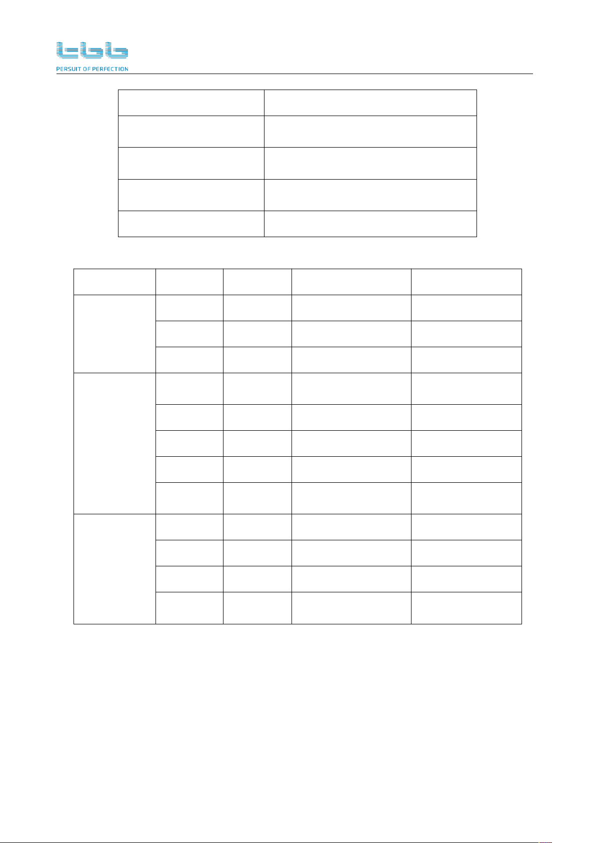
Table 6-2 LED indicator and audible alarm
LED name
LED color
LED status
Indication
Beep
INV/
INV OK
N/A
Extinguish
Inverter is off
/
Green
ON
Normal
/
Green
Flashing
Power saving mode
/
BATTERY/
Battery Level
Red
ON
<11.0V/<22.0V
Intermittent beep,
once every sec
Orange
ON
11.0~11.5V/22~23V
/
Green
ON
11.5~15.0V/23~30V
/
Orange
ON
15.0~15.5V/30~31V
/
Red
ON
>15.5V/>31V
Intermittent beep,
once every sec
LOAD/
Load Level
N/A
Extinguish
<20%
/
Green
ON
20%~50%
/
Orange
ON
50%~90%
/
Red
ON
>90%
Intermittent beep,
once every sec
This manual suits for next models
5
Table of contents
Other TBB Inverter manuals


Popular Inverter manuals by other brands

Mitsubishi Electric
Mitsubishi Electric FR-E500 Series instruction manual

Daikin
Daikin F-Series Service manual

Chint Power
Chint Power CPS SCA25KTL-DO Installation and operation manual

Shihlin electric
Shihlin electric SL3 Series user manual

SOLIS
SOLIS S6-EA1P3K-L-S Quick installation guide

Generac Power Systems
Generac Power Systems 91355 installation manual


