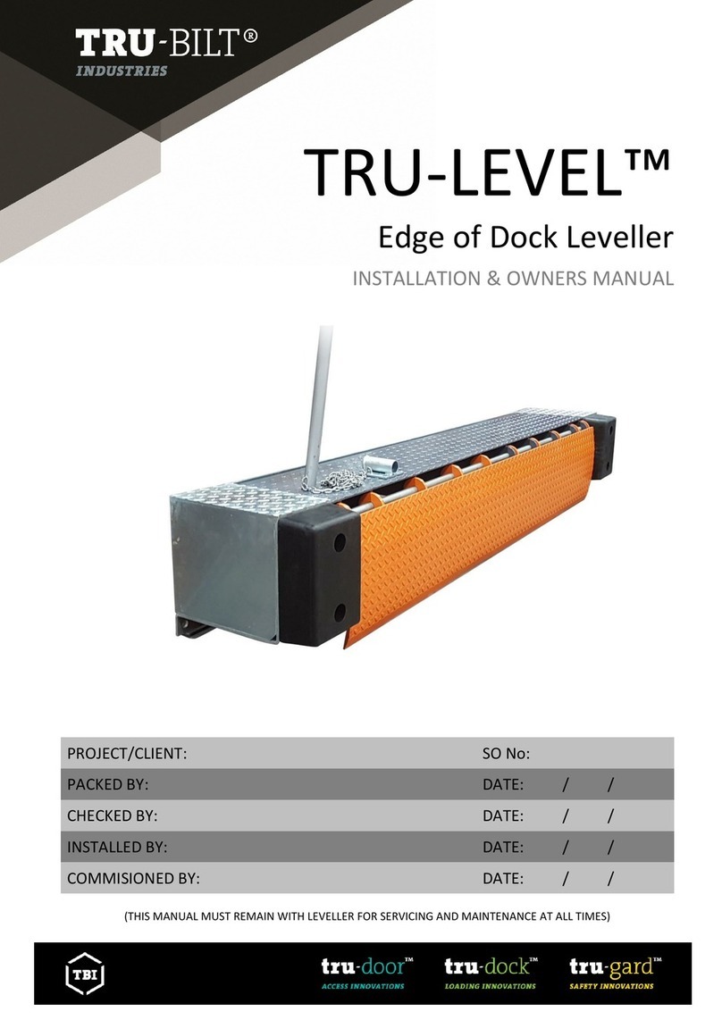
TBI TRU-THERM Operating instructions

PROJECT/CLIENT:
SO:
PACKED BY:
DATE: / /
CHECKED BY:
DATE: / /
INSTALLED BY:
DATE: / /
COMMISIONED BY:
DATE: / /
(THIS MANUAL MUST REMAIN WITH DOOR FOR SERVICING AND MAINTENANCE AT ALL TIMES)

TRU-THERM™INSTALLATION & OWNERS MANUAL
2
Packing List
Part Name
Quantity Per Door
Despatch
check 1
Despatch
check 2
Delivery
check
•
•
Free Phone Australia: 1800 144 888
Free Phone New Zealand: 0800 144 999
Website: www.tru-bilt.co.nz

TRU-THERM™INSTALLATION & OWNERS MANUAL
3
Contents
Safety Warnings ……………………………………..…………….………………………………………..………….. 3
Installation Pre-Check …….………………………..…….……………………………..………..………….…..…. 4
Commissioning Instructions ……………………………..……..…………………..………………….…… 5 - 24
Operation Instructions ……………………………..………………………..………..…………….……..…….… 25
Electric Operation …….………………………..………………………………………………………….….….…… 25
Troubleshooting ....….……………………..……………….…………………………………………….…..………26
Maintenance & Repair .....….……………………..……………….…………………………….……..………… 27
Warranty …………………………………….…………………………………………………….………….…..……… 28
Preface
•The installation of TRU-THERM™ Sectional Doors is for experienced installers only
and this manual must be followed carefully.
•All warnings and safety precautions must be followed at all times.
•A selection of hand and power tools will be required depending on the type of
fixing available.
•A scissor lift or scaffold may also be necessary for safe installation.
•Please don’t hesitate to call a qualified door technician at any time for assistance.
Safety Warning
•All necessary safety precautions must be carried out to ensure a safe working
environment for yourself and those around you.
•Use correct work platforms when working at heights. Precautions must be taken
to prevent people from being injured from falling objects.
•All electrical work and connection of the motor and controller must be carried out
by a fully qualified electrician.
WARNING! - Failure to follow precautions in this manual
may result in severe personal injury or death.

TRU-THERM™INSTALLATION & OWNERS MANUAL
4
Installation Pre-check
Before starting installation, read the following instructions
A. Packing slip shows door size. Do you have the right door? Also, check to make
sure you have received the correct number of bundles, boxes, etc.
B. Is the door opening framed to the correct size?
C. Check Table 1, and Figure A below, to determine amount of headroom, sideroom,
and back space room required for this particular door. Make sure NOW that all of
these clearances are available.
D. Suitable spring anchor pads or other anchorage for shaft bearings must be
provided. All spring or bearing anchor pads must be flush with and not extend
into the room any further than the jambs. Are pads now in place, or can they be
provided for as you progress?
E. Jamb must be plumb and solidly attached to the building. Floor must be level, or
exact grade line established before you start!
Table 1
Configuration
Headroom
Sideroom
Backspace
Standard Lift
Manual
450mm
175mm
DOH
+450mm
Standard Lift
Motor Side
300mm
High Lift
Manual
1700mm
175mm
DOH –
Amount of lift
+ 670mm
High Lift Motor
Side
300mm
Vertical Lift
Manual
DOH +
200mm
175mm
Up to
600mm
Vertical Lift
Motor Side
300mm
IMPORTANT SAFETY NOTICE
1. Operate door only when properly adjusted and free of obstructions.
2. Door is constantly under extreme spring tension. Repairs and adjustments, especially to cables and spring assembly, can be
hazardous and should be performed by qualified door service people only.
3. Do not permit children to play with the garage door or electric controls.
4. If door is now, or later becomes, electrically operated, pull down rope MUST be removed.
5. Avoid standing in open doorway or walking thru doorway while electrically operated door is moving.
6. Should door become hard to operate or completely inoperative, it is recommended that a qualified door agency be contacted.
The foregoing safety notice has been approved and recommended by the National Association of Garage Door Manufacturers
(NAGOM).

TRU-THERM™INSTALLATION & OWNERS MANUAL
5
Installation Instructions
Step 1- Fit Door Opening Seal
•The Door Opening seal supplied with your door kit should be fixed to the sides of
the door opening as shown below in figures B and C.
•Extreme Caution must be taken when attaching the seal on or around an
electric heat trace. Door tracks may also need to be packed off the wall.
•It is recommended that the seal is attached in one continuous length to finish
100mm above the lintel to ensure the best possible seal is obtained.
•TRU-THERM™Doors are manufactured with a standard overlap of 50mm on each
side.
Door seals
FIGURE B
FIGURE C

TRU-THERM™INSTALLATION & OWNERS MANUAL
6
Step 2- Prepare Bottom Panel
•Locate the bottom door panel with the weather seal and bottom brackets already
attached. See figure D below.
•Two rollers should be fitted to the bottom brackets along with the axle spacers
provided.
•IMPORTANT: You must use the 10mm spacer to minimise sideways movement of
the 2 bottom rollers!
•Locate four side hinges and attach two on each top corner of the bottom panel.
Use the gold 1/4” self-tapping tek screws provided.
•If door has Cable Break Safety Devices, these will need to be fitted in place of the
bottom wheel brackets shown below.
Axle Spacer - MUST BE FITTED ON EACH SIDE! Bottom wheel bracket
FIGURE D

TRU-THERM™INSTALLATION & OWNERS MANUAL
7
Step 3- Set up Bottom Panel and Tracks
•Centre and level the Bottom door panel in the opening as shown in figure E
below. The panel will overlap the opening by 50mm each side.
•Temporarily attach the vertical tracks to the door jambs using the TL190 brackets
which are attached to the pre-drilled holes in the tracks using the M8x16 dome
head bolts and flange nuts, and then fastened to the wall. The bottom wheel
should be hard in against the spacer to locate the bottom end of the track.
Level
FIGURE E

TRU-THERM™INSTALLATION & OWNERS MANUAL
8
•It is very important that the top of each track is at the same level (shim if
necessary). See table below.
Door Type
Lintel to top of lower/vertical track
Standard Lift
180-190mm below lintel
High Lift
Amount of lift-380= measurement above lintel
Vertical Lift
200-210mm above lintel
•Ensure the tracks are angled further apart at the top than at the bottom to ensure
the door is guided to a central location as it closes. See Figure F below.
Dimension B should be: Dimension A plus 20mm (10mm each side).
•Also ensure the tracks are angled back as shown in Figure G below. Dimension D
should be: at least Dimension C plus 25mm; or as far back as the slots in the top
TL bracket will allow. If the tracks are not angled back, the door seals will be
rubbing all the time.
B
A
FIGURE F FIGURE G

TRU-THERM™INSTALLATION & OWNERS MANUAL
9
Step 4- Install Remaining Panels
•Install the door panels as shown below in Figure H.
•The top panel may be installed now or may wait until step 10 (installer
preference). There should be 20mm clearance between the top panel and the
lintel.
•Install side hinges onto left side of panel by screwing through pre-drilled holes in
end caps, install roller into vertical track, then rotate the panel into position and
stack. Then align panels and secure right hand hardware. (Screws will penetrate
reinforcing struts in panel- see Figure H on next page.)
FIGURE H

TRU-THERM™INSTALLATION & OWNERS MANUAL
10
Step 5- Fit Intermediate Hinges
FIGURE I
•Intermediate hinges should now be fitted to the door with a maximum spacing of
1000mm. See Figure I above. The hinge screws will penetrate the continuous
reinforcing strips as shown in figure I (Detail A).
•Panel strengthening struts (top hat purlins) will be supplied with all doors over
4000mm wide. The first strut should be fixed to the bottom panel and the rest
spaced evenly thereafter.

TRU-THERM™INSTALLATION & OWNERS MANUAL
11
Step 6- Fit Top/Horizontal Tracks
•All track assemblies are supplied cut to length and with the bracket mounting
holes pre-punched.
•All doors come with one of the track layout drawings shown below to show how
they are to be assembled.
Standard Lift
High Lift
Vertical Lift
If your Door Configuration is to be:
•Standard Lift, Go to Step 7A, Page 12
•High lift, Go to step 7B, Page 14
•Vertical Lift, Go to step 7C, Page 15
WHEN COMPLETED PROCEED TO STEP 8.

TRU-THERM™INSTALLATION & OWNERS MANUAL
12
Step 6A- Standard Lift Tracks
FIGURE J
•Fit the TL900 bracket to the wall, 335mm above the top TL190 bracket and then
bolt the alloy curve to the holes at the top of the vertical track. See Figure K
below.
•Ensure both curves are the same distance out from the wall.
FIGURE K

TRU-THERM™INSTALLATION & OWNERS MANUAL
13
FIGURE L
•Locate the Left and Right Horizontal tracks and lift into place. Insert the bolts
through the holes at the front of the track, the TL900 bracket and the alloy curve,
and wind the nuts on to the bolts.
•Temporarily support the back end of the track with a track stand or similar.
If a jack shaft motor is to be fitted to the door later, lift the back of the horizontal
track as much as headroom allows (up to 20mm for every one metre of track).
Support track every 1500mm
FIGURE M
•The rear hanger must be located near the buffer springs at the back of the
horizontal track. Buffer springs are fitted in step 13.
•Intermediate hangers must be spaced at approximately 1500mm centres (spaced
back from the rear hangers towards the door opening) unless the door is
particularly wide or heavy, when they should be spaced at 1000mm centres.
•When you have completed all the above and tightened all track bracket bolts,
proceed to Step 7 on page 16.

TRU-THERM™INSTALLATION & OWNERS MANUAL
14
Step 6B- High Lift Tracks
FIGURE N
•High Lift tracks and hardware are designed to raise the horizontal tracks higher
off the floor than Standard Lift tracks where needed to clear obstructions.
•Standard High Lift doors require up to 1700mm of headroom which will give the
door 1400mm of lift. (This is measured from the top of the door opening to the
underside of the horizontal track.)
•Fit the TL900 bracket to the wall, 335mm above the top TL190 bracket, and then
bolt the alloy curve to the holes at the top of the vertical track. (See FIGURE K on
page 12).
•Locate the Left and Right Horizontal tracks and lift into place. Insert the bolts
through the holes at the front of the track, the TL900 bracket and the alloy curve,
and wind the nuts on to the bolts.
•Temporarily support the back end of the track with a track stand or similar.
If a jack shaft motor is to be fitted to the door later, lift the back of the horizontal
track up by 20mm for every one metre of track.
•The rear hanger must be located near the buffer springs at the back of the
horizontal track. Buffer springs are fitted in step 14, page 23.
•When you have completed all of the above and tightened all bolts, proceed to
Step 7 on page 16.

TRU-THERM™INSTALLATION & OWNERS MANUAL
15
Step 6C- Vertical Lift Tracks
FIGURE O
•Vertical Lift tracks and hardware are designed to lift the door up the wall above
the door opening as shown below. This is only possible when there is adequate
headroom available.
•Vertical Lift doors require a headroom measurement of door height +200mm.
This is measured from the top of the door opening to the top of the vertical
track.
•Vertical Lift doors have longer TL brackets supplied for the top track which angle
the door away from the wall to clear the cable drums. These are fitted as per the
track layout drawing supplied.
•Once you have mounted the tracks securely, proceed to Step 7 on the next page.

TRU-THERM™INSTALLATION & OWNERS MANUAL
16
Step 7- Set up Shaft and Springs
•Identify the appropriate spring configuration for your door shown in Figure P
below and Figure Q on next page.
•It is very important to ensure RED cable drums are always on the LEFT side of the
door and BLACK cable drums on the RIGHT. (From Inside Looking Out) See Figure
P below.
FIGURE P (Standard Lift door with 2 springs)
Please note: Torsion Shaft must be level and square to wall!
WARNING!
Spring anchor brackets must have extra strong fixing as large forces are applied when springs
are tensioned!

TRU-THERM™INSTALLATION & OWNERS MANUAL
17
FIGURE Q

TRU-THERM™INSTALLATION & OWNERS MANUAL
18
•Mount CD150 Cable Drum brackets and shaft support brackets (if required) to
wall. The shaft support bracket is mounted above the centre of the doorway, or
to suit available strong timber fixing. (Remember to allow 120-170mm for the
springs to grow when tensioning.)
•Fit torsion spring assemblies, spring bearings, cable drums, shaft bearing
assemblies and the torsion coupling to the torsion shaft. Ensure the locking ring
spacer is fitted between the cable drum and outer shaft bearing assembly on the
CD150 bracket.
•Fit the bent key steel for the cable drum and torsion coupling and then tighten
the grub screws into the shaft and key steel only. IMPORTANT! Fit the hose
clamp supplied around each key steel and use the thread locker supplied on the
torsion coupling grub screws. (The torsion coupling connecting bolts will be
tightened in Step 9.)
•Now bolt the spring assemblies to the Spring Anchor brackets which are bolted to
the cable drum brackets already on the wall. See Figure R below (NB: Standard
lift door shown).
•Now check that the shaft is straight and level.
Cable drum
Bracket
FIGURE R

TRU-THERM™INSTALLATION & OWNERS MANUAL
19
Step 8- Attach Cables to Drums
•Feed cables (attached to bottom bracket; see figure D on page 6) up behind the
vertical tracks and attach to the drums. Tighten the set screws on one drum, and
then rotate drum and shaft until cable is tight. Attach vice grip very tightly to
shaft, with end resting against wall. This will keep cable from unwinding. Now,
turn other drum until cable is taut and tighten set screws and also tighten the
connecting bolts on the torsion coupling.
•IMPORTANT NOTE –Please ensure both cables have the same amount of
tension! Adjust this with the torsion coupling in the centre.
Step 9- Ensure Door is Fully Assembled
•If you did not mount the top door panel in Step 4, do so now. Also make sure you
remembered to attach the top wheel brackets, panel strengthening struts (if
required) in step 6 and anything else, such as door locks, which will add weight to
the door.
•IMPORTANT NOTE - Ensure all bolts on the torsion shaft coupling and spring
anchor brackets are tight and fixings to the wall are strong and secure before
tensioning the springs.

TRU-THERM™INSTALLATION & OWNERS MANUAL
20
Step 10- Tension Springs
•Before tensioning springs clamp a locking plier on to the door track as shown on
next page in figure T. This will prevent the door from opening during tensioning.
•Use a permanent marker to mark a clearly visible, straight line along each spring
as shown in figure S below. This enables you to count the number of turns when
tensioning the springs.
Use permanent marker only
FIGURE S
•See figure T below to calculate the approximate number of turns your springs will
require. You will need the code number off your cable drums.
FIGURE T
WARNING!
Spring Mechanism is under extreme tension. It is recommended that a qualified door
agency be contacted for installation or adjustments.
Table of contents
Other TBI Lifting System manuals
Popular Lifting System manuals by other brands

BlueSky Mast
BlueSky Mast AL350 Quick reference sheet
Nussbaum
Nussbaum 4.80 H SST Operating Manual and Inspection Book

IMER
IMER AIRONE 300 N Operating, maintenance, spare parts manual
RITE-HITE
RITE-HITE PitMaster II Installation/Service/Owner's Manual

Ingersoll-Rand
Ingersoll-Rand Zero Gravity Air Balancer 2.0 user manual

Westfalia
Westfalia Farm Jack instruction manual
