Hillrom Liko Multirall 200 User manual

Product Descripon
In this document, the person being lied is referred to as the paent, and the person helping is referred to as the caregiver.
Mulrall™ 200
Overhead li
Instrucons for Use
LikoTM MulrallTM 200 overhead li Prod. No. 3130001
7EN125103 Rev. 13
ENGLISH 2020
g. 2g. 1
Mulrall™ 200 overhead li is a general-purpose li
with the intended use in; health care, intensive care and
rehabilitaon. Mulrall 200 overhead li is easy to move
between facilies and useful for room-to-room transions.
Mulrall™ 200 overhead li can be mounted to the
rail carriage in two dierent ways;
- mounted with the li strap under the li unit (g. 1), or
- mounted with the li strap above the li unit (g. 2).
Intended for use in all common li and transfer situaons,
for example, between bed/wheelchair, to/ from oor,
toilet visits, gait training, and for horizontal lis with
stretchers.
Accessories
The Liko™ product range includes several sling models
in many sizes and dierent designs. Also available as an
accessory is a praccal trolley for transfer and storage
of the li, as well as an Extension Arm, for use when
connecng the listrap to the rail carriage.
Mulrall™ 200 overhead li is adapted to LikoTM Quick
Release System for safe and easy changing of liing
accessories.
Multirall
Multirall
Multirall
Multirall
IMPORTANT!
Liing and transferring a paent always involves a certain level of risk. Read the instrucons for use for both the paent li and
liing accessories before use. It is important to completely understand the contents of the instrucons for use. The equipment
should only be used by trained personnel. Ensure that the liing accessories are suitable for the li used. Exercise care and cauon
during use. As a caregiver, you are always responsible for the paent’s safety. You must be aware of the paent’s ability to make it
through the liing situaon. If something is unclear, contact the manufacturer or supplier.

2
7EN125103 Rev. 13 • 2020 www.hillrom.com
Table of Contents
Symbol Descripon .......................................................................................................................... 3
Safety Instrucons ........................................................................................................................... 4
Denions ....................................................................................................................................... 5
Technical Data ................................................................................................................................... 5
Dimensions ......................................................................................................................................... 6
EMC Table ......................................................................................................................................... 6
Assembly .......................................................................................................................................... 10
Operaon ......................................................................................................................................... 15
Charging the Baeries ...................................................................................................................... 17
Room-to-Room transfer ..................................................................................................................... 18
Maximum Load ................................................................................................................................. 20
Recommended Liing Accessories ...................................................................................................... 20
Simple Troubleshoong ..................................................................................................................... 23
Recycling Instrucons ........................................................................................................................ 24
Cleaning and Disinfecon .................................................................................................................. 24
Inspecon and Maintenance ............................................................................................................. 28

3
7EN125103 Rev. 13 • 2020 www.hillrom.com
Symbol Descripon
These symbols can be found in this document and/or on the product.
Symbol Descripon
For indoor use only.
The product has extra protecon against electric shock (Insulaon Class II).
Protecon level against electric shock Type B.
Warning; this situaon requires extra care and aenon.
Read instrucons for use before use.
CE-mark.
IP N1 N 2 Protecon level against: ingress of solid objects (N1) and ingress of water (N2).
Legal Manufacturer.
Date of manufacture.
Cauon! consult instrucons for use.
Read instrucons for use before use.
Baery.
,
Pb
,
All baeries in this product must be recycled separately.
- Pb underneath the symbol indicate baeries containing lead
- Single Black line underneath the symbol indicate this product have been placed on the market aer 2005.
UL Recognized Component Mark for Canada and the United States.
EFUP, Environmental Friendly Usage Period (years).
Environmentally-friendly product which can be recycled and reused.
The Australian Safety/EMC.
PSE Mark (Japan).
Product Idener.
Serial Number.
Medical Device.
Recyclable.
The safety and essenal performance of medical electrical equipment.
Proof of Product compliance to North American safety standards.
Non-ionizing electromagnec radiaon.
X%
Y% ≤Tmin
Duty cycle for non-connuous operaon.
The maximum acve operaon me X% of any given me unit, followed by a deacvaon me, Y%.
The acve operaon me shall not exceed the specied me in minutes, T.
(01) 0100887761997127
(11) Y Y MM D D
(21) 012345678910
GS1 Data Matrix Barcode that may contain following informaon
(01) Global Trade Item Number
(11) Producon Date
(21) Serial Number
4
7EN125103 Rev. 13 • 2020 www.hillrom.com
Safety Instrucons
No modicaon of the product is allowed.
Portable RF communicaons equipment (including peripherals such as antenna cables and external antennas) should be
used no closer than 30 cm (12 inches) to any part of the li, including cables specied by the manufacturer. Otherwise,
degradaon of the performance of this equipment could result.
Use of the product adjecent to other equipment should be avoided because it could result in improper operaon, if
such use is neccessary, observe and verify that the other equipment is operang normally.
Electromagnec disturbance, may aect the liing performance of the product. Modicaon using other parts than original
spare parts (cables etc.) may aect the electromagnec compability of the product. Parcular care must be taken when
using powerful sources of electromagnec disturbance, such as diathermy, etc, so that, for example, diathermy cables are not
posioned on or near the li.
If you have any quesons, please consult the responsible assisve device technician or the supplier.
The li is not suitable for use in the presence of ammable mixtures, for example, in areas where ammable goods are
stored.
Before liing, always make sure that:
• the li strap is not twisted or worn and can move in and out of the li freely
• the liing accessories are not damaged
• the liing accessory is correctly and safely applied to the paent in order to prevent injuries
• the liing accessories are properly aached to the li
• the liing accessories hang vercally and can move freely
• the sling bar latches are intact; missing or damaged latches must always be replaced
• the sling’s strap loops are correctly connected to the sling bar hooks when the sling straps are extended, but before the
paent is lied from the underlying surface.
Incorrect aachment of sling to slingbar may cause severe injury to the paent.
Only use the MulrallTM overhead li with a carriage, adapter, sling bar and other accessories approved by LikoTM.
Never leave a paent unaended during a liing situaon!
Before use, make sure that:
• the li is assembled in accordance with the assembly instrucons
• the liing accessories are properly aached to the li
• the baeries have been charged for at least 8 hours
• you have read the instrucon for use for the li and liing accessories
• personnel using the li are informed of the correct use of the li and liing accessories
• the liing accessory is selected appropriately, in terms of type, size, material and design with regard to the paent’s needs.
Installaon of carriages for MulrallTM overhead li shall be made by personnel authorized by LikoTM in accordance with
the installaon instrucons and recommendaons for the current li system.
Intended use
This product is not intended to be used by the paent alone. Liing and transferring a paent shall always be performed
with the assistance of at least one caregiver. This product is used as a means to perform the li but is not in contact with the
paent; therefore we do not go into the various paent condions in this instrucon for use.
Contact your Hill-Rom representave for support and advice.
Mulrall™ 200 overhead li has been tested by an accredited tesng instute

5
7EN125103 Rev. 13 • 2020 www.hillrom.com
1. Carriage Hook (S65 Carriage with Single
Hook)
2. Q-Link II (quick fastener)
3. Q-Link (quick fastener)
4. Emergency stop
5. End cover
6. Mechanical Emergency Lowering
7. Electrical Emergency Lowering/Raising
8. Contact for hand control
9. Hand control
10. Hang-up HandControl Hanger
11. Sling bar
12. Latches
13. Quick-Release Hook
14. Carriage Adapter MR for S65
15. Li unit
16. Handle
17. SSP Limit Switch
18. Extension Belt connector
19. Li strap
Denions
3
6
1
8
5
7
9
4
10
Multirall
Multirall
11
13
14
16
17
18
19
15
2
12
Multirall
Multirall
Technical Data
Mulrall™ 200 overhead li is equipped with an SFS (Single Fault Safety) safety drum. This safety design provides protecon
against uncontrolled lowering. The li strap has a tenfold safety.
Component X1 (Murata CSTCC4M00G53) on PCBA contains a SVHC, Lead tanium zirconium oxide (Pb(Ti,Zr)O3), which
exceeds the limit according to REACH Regulaon.
Intermient
power:
Int. Op 10/90, acve operaon max 6 min.
Sound level: 62.2 dB(A)
Protecon class: IP 30 (li unit)
IP 43 (hand control)
Operang forces
of controls:
Buon on hand control: 4.5 N
Buon on end cover: 4 N
Surrounding
funconal
environment:
Temperature: +10°C to +40°C, (50° F to 122° F)
Humidity: 20% to 90% at 30°C non-condensing,
Atmospheric pressure: 700-1060hPa.
Intended for indoor use.
Type B, in accordance with the electrical shock protecon
class.
Class II equipment.
Maximum load: 200 kg (440 lbs)
Baeries: 2 X 12 V DC, (2.4 Ah - 2.6 Ah), Valve-regulated
lead-acid gel-type baeries. New baeries are
provided by Liko®.
Baery charger: SMP CC-10-43-24; 100-240 V AC,
40-60 Hz, max 600 m A
Liing speed: 60 mm/s (2.3 in/s)
Liing interval: 1600 mm (63 in)
Electrical data: 24 V DC, 8.5 A
Li motor weight:
8.7 kg (19 lbs)
Emergency
lowering device:
Mechanical and electrical

6
7EN125103 Rev. 13 • 2020 www.hillrom.com
Overhead
view
Lateral view
CSP (Central Suspension Point)
* Min. distance from ceiling to CSP at max. liing height.
** Installaon dimensions: the distance between the aachment point for the li unit on the carriage and the CSP at max. liing height.
*** Liing interval: the distance between max. liing height and min. liing height measured in CSP.
Measurements in mm.
C
A
B
H** D*
L***
A B CD* H** L***
264 295 210 443 308 1600
Ceiling
A B CD* H** L***
10.4 11.6 8.3 17.4 12.1 63.0
Measurements in inch.
Dimensions
Guidance and manufacturer’s declaraon – electromagnec emissions
The overhead li is intended for use in the electromagnec environment specied below. The customer or the user of the
overhead li should assure that it is used in such an environment.
”Essenal performance according to the manufacturer: The li shall not move unintenonally while being submied to
disturbances.”
Emissions test Compliance Electromagnec environment - guidance
RF emissions
CISPR 11
Group 1 The overhead li uses RF energy only for its internal funcon.
Therefore, its RF emissions are very low and are not likely to
cause any interference in nearby electronic equipment.
RF emissions
CISPR 11
Class B
The overhead li is suitable for use in all establishments inclu-
ding domesc establishments and those directly connected
to the public low-voltage power supply network that supplies
buildings used for domesc purposes.
Harmonic emissions
IEC 61000-3-2
Class A
Voltage uctuaons/ icker emissions
IEC 61000-3-3
Complies
EMC Table

7
7EN125103 Rev. 13 • 2020 www.hillrom.com
Guidance and manufacturer’s declaraon – electromagnec immunity
The overhead li is intended for use in the electromagnec environment specied below. The custo-
mer or the user of the overhead li should assure that it is used in such an environment.
”Essenal performance according to the manufacturer: The hoist shall not move unintenonally while
being submied to disturbances.”
Immunity test IEC 60601 test level Compliance level Electromagnec
environment - guidance
Electrostac discharge
(ESD)
IEC 61000-4-2
+/- 6 kV contact
+/- 8 kV air
+/- 6 kV contact
+/- 8 kV air
Floors should be wood, concrete or
ceramic le.
If oors are covered with synthec
material,
the relave humidity should be at
least 30 %.
Electrical fast
transient / Burst
IEC 61000-4-4
+/- 2 kV for power supply
lines
+/- 1 kV for input/output
lines
+/- 2 kV for power supply
lines
+/- 1 kV for input/output
lines
Mains power quality should be that
of a typical commercial or hospital
environment.
Surge
IEC 61000-4-5
+/- 1 kV Line to Line
+/- 2 kV Line(s) to Earth
+/- 1 kV Line to Line
+/- 2 kV Line(s) to Earth
Mains power quality should be that
of a typical commercial or hospital
environment.
Voltage dips, short
interrupons and
voltage variaons on
power supply input lines
IEC 61000-4-11
<5 % UT
(>95 % dip in UT)
for 0,5 cycle
40 % UT
(60 % dip in UT)
for 5 cycles
70 % UT
(30 % dip in UT)
for 25 cycles
<5 % UT
(>95 % dip in UT))
for 5 sec
<5 % UT
(>95 % dip in UT)
for 0,5 cycle
40 % UT
(60 % dip in UT)
for 5 cycles
70 % UT
(30 % dip in UT)
for 25 cycles
<5 % UT
(>95 % dip in UT))
for 5 sec
Mains power quality should be that
of a typical commercial or hospital
environment. If the user of the
[Equipment or System] requires
connued operaon during power
mains interrupons, it is recom-
mended that the [Equipment or
System] be powered from an unin-
terrupble power supply or baery.
Power frequency (50/60
Hz) magnec eld
IEC 61000-4-8
3 A/m 3 A/m Power frequency magnec elds
should be at levels characterisc
of a typical locaon in a typical
commercial or hospital environ-
ment
NOTE UT is the a.c. mains voltage prior to applicaon of the test level.

8
7EN125103 Rev. 13 • 2020 www.hillrom.com
Guidance and manufacturer’s declaraon – electromagnec immunity
The overhead li is intended for use in the electromagnec environment specied below. The custo-
mer or the user of the overhead li should assure that it is used in such an environment.
”Essenal performance according to the manufacturer: The hoist shall not move unintenonally while
being submied to disturbances.”
Immunity test IEC 60601 test level Compliance level Electromagnec environment - guidance
Conducted RF
IEC 61000-4-6
Radiated RF
IEC 61000-4-3
3 Vrms
150 kHz to 80 MHz
10 V/m
80MHz to 2,5GHz
3 Vmrs
10 V/m
Portable and mobile RF communicaons
equipment should be used no closer to any
part of the overhead li, including cables,
than the recommended separaon distance
calculated from the equaon applicable to the
frequency of the transmier.
Recommended separaon distance
Pd 2,1=
P
d2,1=
d = 0,35 80 MHz to 800 MHz
Pd 7,0=
800 MHz to 2,5 GHz
where P is the maximum output power rang
of the transmier in was (W) according to
the transmier manufacturer and d is the
recommended separaon distance in meters
(m).
Field strengths from xed RF transmiers, as
determined by an electromagnec site survey,
a should be less than the compliance level in
each frequency range. b
Interference may occur in the vicinity of
equipment marked with the following symbol.
NOTE 1 At 80MHz and 800MHz, the higher frequency range applies.
NOTE 2 These guidelines may not apply in all situaons. Electromagnec propagaon is aected by absorpon and reected
from structures, objects and people.
a Field strengths from xed transmiers, such as base staons for radio (cellular/cordless) telephones and land mobile
radios, amateur radio, AM and FM radio broadcast and TV broadcast cannot be predicted theorecally with accuracy. To
assess the electromagnec environment due to xed RF transmiers, an electromagnec site survey should be considered.
If the measured eld strength in the locaon in which the overhead li is used exceeds the applicable RF compliance level
above, the overhead li should be observed to verify normal operaon. If abnormal performance is observed, addional
measures may be necessary, such as reorienng or relocang the overhead li.
b Over the frequency range 150 kHz to 80 MHz, eld strengths should be less than 10 V/m.

9
7EN125103 Rev. 13 • 2020 www.hillrom.com
Recommended separaon distances between portable and mobile RF communicaons
equipment and the overhead li
The overhead li is intended for use in an electromagnec environment in which radiated RF distur-
bances are controlled. The customer or the user of the overhead li can help prevent electromagnec
interference by maintaining a minimum distance between portable and mobile RF communicaons
equipment (transmiers) and the overhead li as recommended below, according to the maximum
output power of the communicaons equipment.
Rated maximum output
power of transmier
W
Separaon distance according to frequency of transmier
m
150 kHz to 80 MHz
Pd 2,1=
80 MHz to 800 MHz 800 MHz to 2.5 GHz
Pd 7,0=
0.01 0,12 0,035 0,07
0.1 0,38 0,11 0,22
1 1,2 0,35 0,7
10 3,8 1,11 2,21
100 12 3,5 7,0
For transmiers rated at a maximum output power not listed above, the recommended separaon distance d in meters
(m) can be esmated using the equaon applicable to the frequency of the transmier, where P is the maximum output
power rang of the transmier in was (W) according to the transmier manufacturer.
Note 1: At 80 MHz and 800 MHz, the separaon distance for the higher frequency range applies.
Note 2: These guidelines may not apply in all situaons. Electromagnec propagaon is aected by absorpon and
reecon from structures, objects and people.
P
d2,1=
d = 0,35

10
7EN125103 Rev. 13 • 2020 www.hillrom.com
Approved combinaons
See individual combinaons 1, 2 and 3, below.
Note! no other combinaons are allowed, whether the parts are LikoTM products or products from
another company.
# 3136015
Carriage Hook for MR/LR:
Available as a service part only
#3136040
Extension Arm Adapter MR:
Available as a service part only
Combinaon 1: Q-Link or Q-Link II, # 3136015, # 3136016, # 3136040
# 3136016
Adapter MR/
LR: Available as a
service part only
Q-Link: Available
as a service part
only
Assembly: See chapter ”Assembly to Carriage Hook for MR/LR” in this document.
#3136011
Carriage S65
with single hook
Q-Link II
(Mulrall std)
Combinaon 2: Q-Link or Q-Link II, # 3136011, # 31390013 Incorrect use!
#31390013
Extension Arm Mulrall
Assembly: See ”Assembly to Carriage S65 with single hook” in this document.
Assembly
Q-Link
Available as a
service part only
#3136010
Carriage MR, S50
#31390012
Helping Hand Mulrall
Combinaon 3: Q-Link or Q-Link II, # 3136010, # 31390012
Incorrect use!
Prod. No. 3136010 Available as a service part only.
Prod. No. 31390012 Available as a service part only.
Assembly: See assembly instrucon for item 31390012.
Q-Link II
(Mulrall std)
Q-Link II
(Mulrall std)
Q-Link: Available
as a service part
only

11
7EN125103 Rev. 13 • 2020 www.hillrom.com
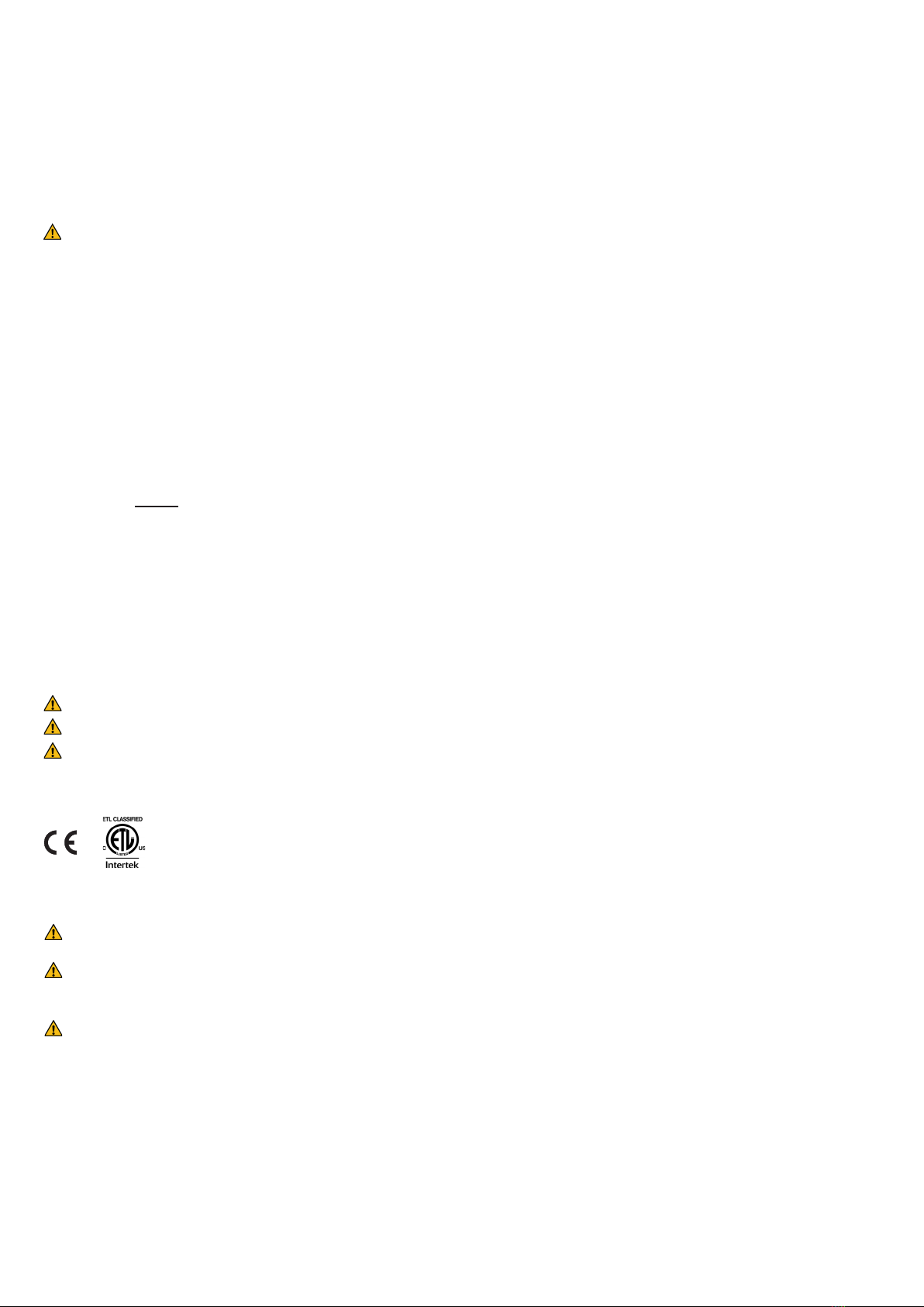
2. Insert the Adapter
MR/LR in to the
Q-Link or Q-Link II.
1. Feed out desired length of li strap by applying tension
to the li strap and simultaneously pressing the electrical
emergency lowering buon.
Operate the li only when tension is applied to the li strap!
5. Connect the desired liing accessory to the universal
connector at the li unit, see chapter “Operaon”.
Before the rst use,
• Charge the li’s baery for at least 8 hours, see chapter “Charging the Baeries”.
• Connect the Handcontrol MR-2 (Prod. No. 3136001) to the contact for handcontrol on the li unit.
4. Raise the li to an appropriate height.
NOTE! Remove the Hang-Up HandControl Hanger when
the li is installed with the li strap above the li unit.
Alt. A, with the li strap above the li unit
This alternave is recommended in cases where the li is to be moved frequently between dierent rail systems, or when the
li is to be used for room-to-room transfers.
A li assembled with the li strap above the li unit must not be used in wet areas.
Multirall
Multirall
3. Connect the Adapter MR/
LR to the Carriage Hook for
MR/LR.
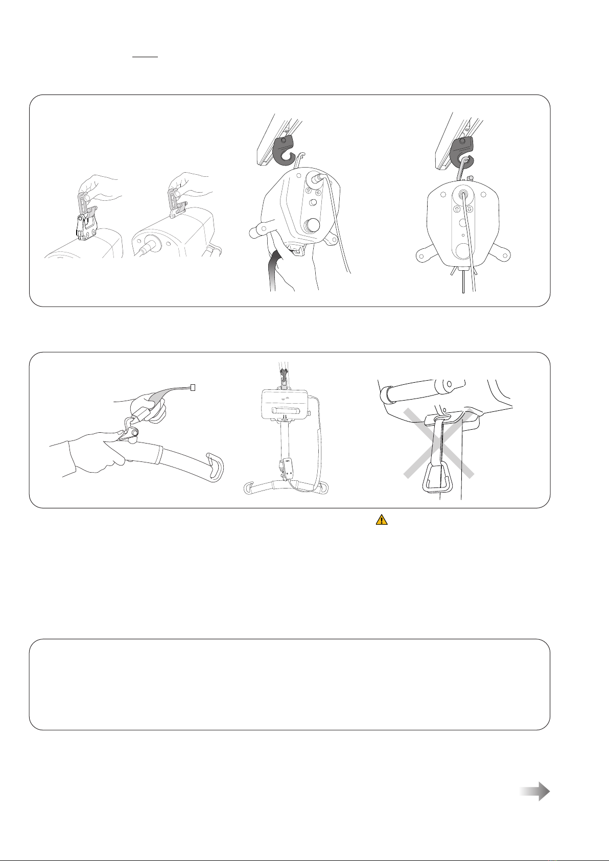
Recommended accessory for (Alt. A, with the li strap above the li unit).
Extension Arm Adapter MR Prod. No 3136040: Available as a service part only.
connect or disconnect the Adapter MR/LR to or from the Carriage Hook for MR/LR.
1. Insert the Adapter MR/LR in to
the Q-Link or Q-Link II.
3. Connect disconnect the Adapter MR
to/from the Carriage hook MR/LR
with the Extension Arm Adapter MR.
2. Place the Adapter MR/LR in
the Extension Arm Adapter MR, in its
intended holder.
Mulrall™ 200 overhead li can be mounted to the Carriage hook for MR/LR in two dierent ways. See alternaves below.
Assembly to Carriage Hook for MR/LR:
12
7EN125103 Rev. 13 • 2020 www.hillrom.com
• the li’s funcons correspond to the markings of the hand
control
• emergency lowering works properly (mechanical and
electrical)
1. Insert the Adapter MR/LR in to the universal
connector or MulRall carriage adapter
3126020.
• the baery charger works properly and the indica-
tor lamps are illuminated during charging
• the baeries are charged.
Aer assembly, make sure that:
Alt. B, with the li strap under the li unit
This alternave is recommended in cases where the li is to be installed in the same rail system for a longer period of me
without being moved.
Mulrall™ 200 overhead li must not
be equipped with a Strap Gripper when
the li strap is mounted under the li
unit. This may result in the Strap Gripper
geng caught in the li strap.
3. Connect the desired liing accessory to the Q-Link or Q-Link II, see
chapter “Operaon”. The li strap and liing accessory are then
suspended under the li unit.
Multirall
Multirall
2. Connect the Adapter MR/LR in to the Carriage Hook for MR/LR.
13
7EN125103 Rev. 13 • 2020 www.hillrom.com
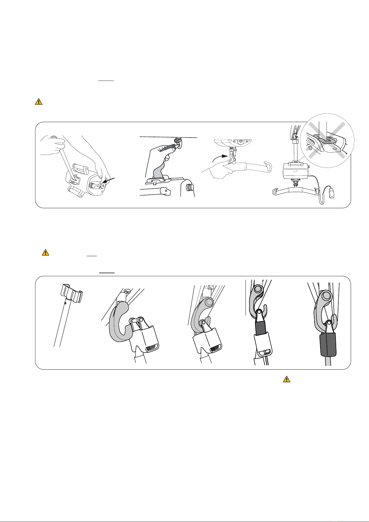
Alt. A, with the li strap above the li unit, using the: Extension Arm Mulrall Art. nr. 31390013
2. Connect the Q-Link
or Q-Link II to the rail
carriage and raise the
li to an appropriate
height.
1. Feed out desired length of li
strap by applying tension to the li
strap and simultaneously pressing
the electrical emergency lowering
buon.
Operate the li only when tension
is applied to the li strap!
Assembly to Carriage S65 with single hook
Before the rst use,
• Charge the li’s baery for at least 8 hours, see chapter “Charging the Baeries”.
• Connect the Handcontrol MR-2 (Prod. No. 3136001) to the contact for handcontrol on the li unit.
Mulrall™ 200 overhead li can be mounted to the Carriage S65 with single hook in two dierent ways, see alternaves below.
Alt. A, with the li strap above the li unit
This alternave is recommended in cases where the li is to be moved frequently between dierent rail systems,
or when the li is to be used for room-to-room transfers.
A li assembled with the li strap above the li unit must not be used in wet areas.
NOTE! Remove the
Hang-Up HandControl
Hanger when the li is
installed with the li strap
above the li unit.
Extension Arm Mulrall
3. Connect the desired
liing accessory
to the universal
connector of
the li unit, see
“Operaon”.
Multirall
Multirall
Multirall
Multirall
3. Aer mounng, make
sure that the Q-Link or
Q-Link II is properly posi-
oned into the carriage
hook and that the li strap
is safely aached to the
hook. The li strap must
hang vercally before li-
ing begins (see illustraon).
1. Place the li strap with the
Q-Link or Q-Link II in the
Extension Arm. Move the
Extension Arm with the
Q-Link or Q-Link II towards
the carriage hook accord-
ing to the illustraon
above.
2. Connect the Q-Link or Q-Link
II to the carriage hook.

14
7EN125103 Rev. 13 • 2020 www.hillrom.com
1. Install the MulrallTM overhead li by
placing the top connector directly into
the carriage hook. Check that the unit is
resng securely at the boom of the hook
before applying a load or liing a paent.
Alt. B, with the li strap under the li unit
This alternave is recommended in cases where the li is to be installed in the same rail system for a longer period of me
without being moved.
Mulrall™ 200 overhead li must not
be equipped with a Strap Gripper when
the li strap is mounted under the li
unit. This may result in the Strap Gripper
geng caught in the li strap.
2. Connect the desired liing accessory to
the Q-Link or Q-Link II, see “Operaon”.
The li strap and liing accessory are
then suspended under the li unit.
Multirall
Multirall
Multirall
Multirall
4. Mulrall™ overhead li is now properly mounted and
ready for use.
Before liing it is important to ensure that the Q-Link
or Q-Link II is securely fastened to the carriage hook. If this
is not the case, repeat steps 1-4 before starng a li.
3. Unhook the
Q-Link or Q-Link II
from the carriage
hook.
4. Remove the Q-Link
or Q-Link II and the
Extension Arm from
the carriage hook.
1. Lower the li motor to a
Mulrall™ overhead li Trolley
or other suitable locaon.
Unload the li strap by apply-
ing tension to the strap, while
pressing the buon, marked
in the desired direcon.
2. Place the Q-Link or
Q-Link II in the Exten-
sion Arm according
to the illustraon
above.
Remove the li strap from the carriage hook S65, using the: Extension Arm Mulrall Art. nr. 31390013

15
7EN125103 Rev. 13 • 2020 www.hillrom.com
Change of liing accessories
Mulrall™ 200 overhead li is adapted to LikoTM Quick Release
System for safe and easy changing of liing accessories.
Liing accessories that are not equipped with a Quick Release Hook
can easily be updated with a Quick Release Hook so that they can be
used with Mulrall. See “Quick Release Hook”, page. 21.
Before liing check that the Quick-release
Hook is correctly aached to the Q-Link or
Q-Link II, see illustraon above.
Quick
Release Hook
Q-Link or
Q-Link II
Li correctly!
Before each li, make sure that:
– the Sling loops at opposite sides of the Sling are at the same height
– all the Sling loops are fastened securely in to the Slingbar hooks
– the Slingbar is level during the li, see Figure 1.
If Slingbar is not level (see Figure 2) or if the sling loops is wrongly
aached to the slingbar (see Figure 3) lower the user to a rm surface
and adjust according to the Instrucon for use of Sling in use.
An improper li can be uncomfortable for the user and cause dam-
age to the li equipment! (see Figure 2 and gure 3).
Figure 1. Figure 2. Figure 3.
Operaon
Operang
Mulrall™ 200 overhead li is operated by lightly pressing the buons on the
hand control. The arrows indicate the direcon of movement. The movement
stops when the buons are released. Mulrall™ 200 overhead li can also be
operated with the corresponding buons on the end cover of the li unit.
The arrow corresponds to the direcon of travel when the li is mounted with
the li strap above the li unit.
Operate the li only when tension is applied to the li strap!
Operate the li only when the li is correctly mounted to the carriage hook.
Hang-up HandControl Hanger
When not in use, the hand control
can be hung on the Hang-up
HandControl Hanger.
Installaon of Latches
Aer installaon, check that the latch
locks and moves freely in the sling bar
hook.

16
7EN125103 Rev. 13 • 2020 www.hillrom.com
Adjustable Fricon Brake
The amount of drag on the li can be
adjusted with the fricon brake on the
carriage. Turn the brake clockwise for
increased resistance and counter clockwise
for reduced resistance.
fricon brake
Electrical Emergency Lowering
In the event that the hand control or electronics malfuncon, the li
can be lowered by pressing the buon on the end cover of the li unit.
The arrow corresponds to the direcon of travel when the li is
mounted with the li strap above the li unit.
Ensure the paent is lowered into a bed, wheelchair or other suitable place.
Mechanical Emergency Lowering
Press the buon marked “Emergency” on
the end cover of the li unit. Note that load
must be applied to the li in order for the
mechanical emergency lowering to work.
Ensure the paent is lowered into a bed,
wheelchair or other suitable place.
SSP Limit Switch
It is important that the liing moon of the li strap is performed as
vercally as possible to ensure safe operaon. The SSP Limit Switch
is intended to stop the liing moon if the li strap is subjected
to harmful strain, for example, if it is pulled sideways or folded
over during the liing moon. The SSP Limit Switch also provides
protecon against pinching. If the SSP Limit Switch has been
acvated and the liing moon stopped, the li strap must rst be
operated downwards before it can be operated upwards again.
Charge Indicator
Two indicators will warn when the baery has a
low charge:
• buzzer that sounds when liing
• LED that is lit during liing.
When either of these signals sounds or illuminates,
the unit should be charged as soon as possible. See
“Charging the Baeries” below.
Acvate Reset
Emergency Stop
Enable the emergency stop: press the red buon.
Reset the emergency stop: turn the buon in the direcon indicated
by the arrows on the buon.
The red buon on the li unit end cover is intended for use in an
emergency situaon. When the buon is pressed, contact between
the motor and power source is broken, which stops the liing moon.

17
7EN125103 Rev. 13 • 2020 www.hillrom.com
In order to ensure maximum baery life, it is important to charge the
baeries regularly. We recommend that you charge the baeries aer use
or every night.
The baeries are fully charged aer approximately 8 hours. When fully
charged, baeries in good condion are sucient for approximately 60 li
cycles. The connector cable of the baery charger cannot be repaired. If the
cable is damaged, it should be replaced by a new one!
Charging
1. Check to ensure that the emergency stops are not pressed in during
charging.
2. Place the hand control in its intended place on the charger.
3. Connect the charger to an electrical outlet (100-240 V AC).
The charging starts automacally. The green LED indicates that the
charger is connected to a power supply. The yellow LED indicates that
the baery is charging. When the baery is fully charged, the charger is
switched o automacally and the yellow LED turns o.
NOTE! If the li is not to be used for a longer period of me, the hand
control should be placed in the charger. If the charger is not connected to
a power supply, the emergency stop buon should be pressed in order to
prevent the baery from discharging.
Charging the Baeries
1.
3.
2.
Green
Yellow
White
(no funcon)
Prod. No. 3126101- 3126104
The AC connector of the charger unit
must be easy accessible to the operator.
Please read the instrucon for use before use.
Baery is charging when yellow led is lit.
AC is connected when green led is lit.
18
7EN125103 Rev. 13 • 2020 www.hillrom.com
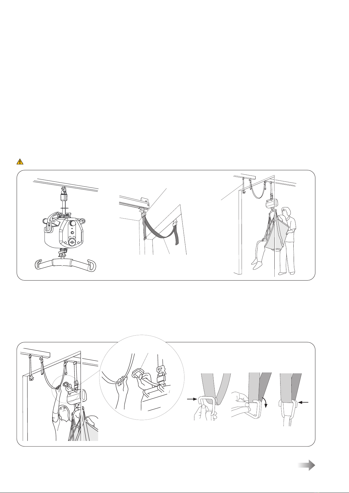
Room-to-Room transfer
Connect the Strap Gripper with both hooks to the
Room-to-Room Strap, see illustraon to the right.
R2R strap
Install the li according to assembly
alternave A. Install the Strap Gripper
in accordance with applicable assembly
instrucons.
Room 1
Room 2
The LikoTM R2R (Room-to-Room) system is an eecve soluon for safe and easy transfer of paents between two or more
rooms. The R2R system is mounted without making openings in walls over doors, and full isolaon is therefore retained
between the rooms supported by the system.
In order to perform room-to-room transfers with Mulrall™ 200 overhead li, the following condions are required:
• Both rooms have separate rail systems, each with a carriage mounted in the rail.
• Between the rooms, suspended under the doorframe, a Room-to-Room Strap is mounted, acng as a bridge between the
rooms.
• Mulrall™ 200 overhead li is equipped with a Strap Gripper, which is installed to either of the Extension Belt connectors
on the li.
• An adjustable extension belt is mounted to the carriage, in order to obtain an appropriate liing height. Alternavely, if the
liing height becomes too low when using the Extension Belt, the Extension Arm Mulrall/Mulrall Helping Hand can be
used for connecng Q-Link II or Q-Link directly to the carriage hook, providing a maximum liing height.
Room-to-Room Transfer
Below is a descripon of an R2R transfer with Mulrall, Strap Gripper, Room-to-Room Strap and adjustable Extension belt.
Check carefully at each stage that the Q-Link or Q-Link II is correctly applied to the carriage hook/extension belt!
Install the Room-to-Room
Strap between the two rooms.
For installaon and length
adjustment, see applicable
assembly instrucons.
Mulrall is pending in the carriage, alternavely
in an extension belt, in room 1. Move the li
with the paent forwards, as close as possible
to the doorway. Lower the paent as far down
as is comfortably possible, but not so far that
the caregiver cannot reach the Room-to-Room
Strap with the Strap Gripper.
Extension Belt
Strap Gripper

19
7EN125103 Rev. 13 • 2020 www.hillrom.com
Only when the li strap runs straight into the li unit can the
transfer to room 2 proceed (see small illustraon). Raise the li
unl the weight of the paent has been fully transferred to the
carriage in room 2.
While the li is raised, it is very important to ensure that the
li strap is not twisted, in order for it not to fold when it enters
the li unit.
Then disconnect the Strap Gripper.
Move the paent further on in room 2.
Lower the Mulrall™ 200 overhead li
unl the Room-to-Room Strap carries
the full weight of the paent. Then run
out an extra 10 cm (4 in) of li strap to
provide enough slack for disconnecon.
Keep hand tension on the li strap
as you run it out of the li motor.
Disconnect the li strap from the carriage/extension belt in room 1
and connect it to the carriage/extension belt in room 2. To prevent the li strap
from twisng, which in turn may cause the SSP limit switch to acvate
(see p. 16), the li unit must be turned manually so that the li strap is straight
when it enters the li unit (see small illustraon).
Check carefully to ensure that the Q-Link or Q-Link II is correctly applied
to the carriage hook/extension belt!

20
7EN125103 Rev. 13 • 2020 www.hillrom.com
Universal SlingBar 350 with Quick-release Hook Prod. No. 3156084
Fixed connecon, prod. no. 3156074*
Max. load 300 kg (660 Ibs)
Universal SlingBar 450 with Quick-release Hook Prod. No. 3156085
Fixed connecon, prod. no. 3156075*
Max. load 300 kg (660 Ibs)
Universal SlingBar 600 with Quick-release Hook Prod. No. 3156086
Fixed connecon, prod. no. 3156076*
Max. load 300 kg (660 Ibs)
Universal SlingBar 670 Twin with Quick-release Hook Prod. No. 3156087
Fixed connecon, prod. no. 3156077*
Max. load 300 kg (660 Ibs)
Universal SideBars 450 Prod. No. 3156079
including bag
Max. load 300 kg (660 Ibs)
Sling Cross-bar 450 with Quick-release Hook Prod. No. 3156022
Fixed connecon, prod. no. 3156021*
Max. load 300 kg (660 Ibs)
Sling Cross-bar 670 with Quick-release Hook Prod. No. 3156019
Fixed connecon, prod. no. 3156018*
Max. load 300 kg (660 Ibs)
* Sling bars with xed connecon can be equipped with Quick-release Hook
Carriage Adapter MulRall for S65 Prod. No 3126020
Recommended Liing Accessories
Using liing accessories other than those approved can entail a risk.
Recommended sling bars and accessories for Mulrall™ 200 overhead li are described below.
For addional guidance in selecng a sling, study the instrucon for use for the respecve sling models. Here, you will also nd
guidance for combining Liko® sling bars with Liko® slings.
Contact your Hill-Rom representave for advice and informaon on the Liko® product range.
Maximum Load
Dierent maximum loads may apply to dierent products on the assembled li system: rail, li, sling bar, sling and any
other accessories used. For the assembled li system, the maximum load is always the lowest maximum load rang of any
of the components. For example: a Mulrall™ 200 overhead li that is approved for 200 kg (440 lbs) can be equipped with
a liing accessory that is approved for 300 kg (660 lbs). In this case, the maximum load of 200 kg (440 lbs.) applies to the
assembled li system. Check the markings on the li and liing accessory or contact your Hill-Rom representave if you have
any quesons.
Other manuals for Liko Multirall 200
1
Table of contents
Other Hillrom Lifting System manuals

Hillrom
Hillrom Likorall 242 User manual

Hillrom
Hillrom Liko Ultra Series User manual

Hillrom
Hillrom Liko SafetyVest 93 Manual

Hillrom
Hillrom Liko Golvo 7000 Series User manual

Hillrom
Hillrom Liko M220 Manual

Hillrom
Hillrom Likorall 200 User manual

Hillrom
Hillrom Liko HygieneVest 50 Manual

Hillrom
Hillrom Liko User manual
Popular Lifting System manuals by other brands


SmarterHome
SmarterHome Universal XL installation manual

Huchez
Huchez CT3 instruction manual

Savaria
Savaria DELTA owner's manual

HSS Hire
HSS Hire 70132/3 Operating & safety guide

WITTUR
WITTUR WSG09 Operating and maintenance manual

Challenger Lifts
Challenger Lifts CL10 Installation, operation & maintenance manual


