tbs electronics CROSSFIRE (XF) User manual

TBS CROSSFIRE R/C System Revision 2017-11-07
Adaptive
Long
Range
Remote
Control
System
The TBS CROSSFIRE (XF) system is a R/C link system made for FPV enthusiasts. It features unheard of range
without sacrificing basic functionality such as being immune to interference from onboard equipment, low
latency control or two-way communications including telemetry functionality.
Key features
• Long range, adaptive and robust remote control system for your aircraft
• Immune to on-board noise
• Two-way communication link with real-time link vitals and telemetry
• Self-healing frequency hopping link
• Receiver beacon mode to recover your downed aircraft
• Super easy binding and configuration via built-in OLED display or TBS TANGO remote
• Low latency control for perfect immersive feeling
• Free output mappable 8 output diversity with integrated backup battery or super tiny receiver ( 4g
weight only ) both with up to 12 channel PPM
• Ability to fly with multiple friends at the same time (10 or more)
• Dynamic self-selecting or selectable RF power from 10mW to 2W (local restrictions apply)
• Dedicated head-tracking input option for full FPV immersion
• Transmitter LED shows link health, OLED display for built in configuration
• Expansion port for future feature support
1

Table of content
Attention
Overview
Setup
Connecting CROSSFIRE Standard Transmitter to radio
Using JR-adapter
Using Hitec/Graupner/JR-cable
Using Futaba-cable
Using custom PPM cable
Connecting CROSSFIRE Micro transmitter to radio
Push button functionality
Connecting CROSSFIRE Diversity receiver
Connecting CROSSFIRE Micro receiver
Connecting antenna
Binding
Head-tracking
Set failsafe
BST Connectivity with TBS equipment
Control UNIFY PRO VTX with SmartAudio
Antenna
Operation
Status display
Up- and downlink status
Find mode
Direction finder
How does find mode work
Testing find mode
Preparations
Simulating flight
Simulating a Crash
Search and rescue
Link regained
Transmitter LED status indicator
Receiver LED status indicator
Real-time telemetry using app link
Configuration
Standard transmitter configuration
Micro transmitter configuration
Receiver
PWM or PPM servo output
Receiver SBUS output
Receiver RSSI or/and LQ output
Serial bridge
2

MAVLink
MAVLink APM
Disable telemetry
CRSF
Transmission power
Dynamic transmission power
Transmission frequency
Operating modes
RF Profiles
Re-bind receiver
CRSF Connectivity with flight controller (COLIBRI)
Minimum requirements
Wiring layout
Setting up radio for CRSF
Setting up receiver for CRSF
Configuring BetaFlight for CRSF protocol
Discovering telemetry data sensors
Remote configuration of CORE PRO / CROSSFIRE RX from radio
Requirements
Setup
Telemetry
Firmware upgrade
Installing TBS Agent
Over-The-Air software updates
Emergency update
FAQ
Good practices
3

Specifications
Type:
Long Range Two-Way Remote Control System
Band:
Europe: 868 MHz SRD Band
America: 915 MHz ISM Band
Output RF power:
Micro TX: Selectable 25mW and 100mW
Standard TX: Selectable 10mW to 500mW, additional 1W and 2W available
with external power connected via XT30 socket
RX: 30mW
Receiver sensitivity:
Up to -130dBm
Antenna:
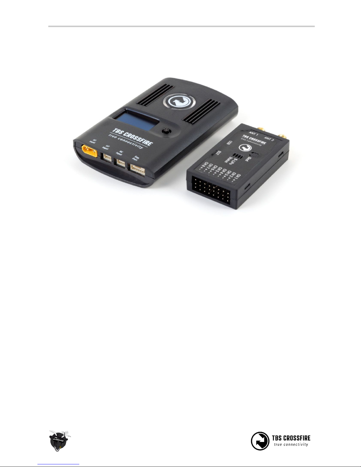
TX: 1x omnidirectional dipole antenna - single stage
RX: 2x omnidirectional dipole antennas - diversity, dual independent RF
stages
R/C Channels:
8-channel traditional PWM (freely mappable ) or up to 12-channel PPM
stream outputs, standard 2.54mm servo connectors
Radio compatibility:
Any radio with PPM stream output ( absolute max. ratings: -0.3V - 15V )
JR Adapter for easy install on JR, FrSky and similar radios
Interface:
Micro TX: RGB LED light, push button, configuration via CRSF (TBS TANGO,
OpenTX ect. )
Standard TX: 1.3-inch OLED display and joystick for configuration, binding
and link stats, real-time telemetry link to any computer, tablet or phone and
Micro-USB for firmware upgrade and configuration via TBS Agent software
Recovery mode:
Diversity RX: Beacon-mode, receiver backup LiPo battery - operating time of
approx. 2 days
Failsafe:
Pre-set servo positions or stops outputting servo pulse - selectable in
configuration menu or via push button
Antenna connector:
Standard SMA (not RP-SMA)
Operating range:
Variable depending on output power and radio environment
Input power:
TX: +3.5 to 12.6V via RC or HT 3-pin input connector, External 2S to 3S LiPo
via XT30 connector (standard RX only)
RX: +4.5V to 8.4V via servo header
All reverse-polarity protected
Power consumption:
TX: 1.1W, at 25mW
TX: 3.2W, at 2000mW
Ports:
Standard RX: 1x BST (the CROSSFIRE RX does not power the BST line), 8x
Servo connectors - Micro RX: V1 1x Servo, 1x BST, V2 4x Servo, 1x BST
Working temperature:
0 - 40°C
Size:
Standard TX: 150 x 80 x 20 mm, Micro TX: 73 x 56 x 35 mm
Diversity RX: 30 x 50 x 12 mm, Micro RX: 40 x 14 x 9.5mm
Weight:
Micro TX: 38 grams
Standard TX: 340 grams
Diversity RX: 25 grams, Micro RX: 3.2 grams
Kit contents:
1x TBS CROSSFIRE TX transceiver unit, 1x TBS CROSSFIRE RX transceiver unit,
1x JR-adapter module, 1x Futaba-cable, 1x JR-cable, 1x custom-cable, 1x XT30
cable, 1x Transmitter SMA antenna, 2x Receiver SMA antenna
4

Attention
These Long Range Systems are capable to use radio frequency transmissions and output power that may
be not allowed in your country.
Please always check your local RF legislation to set the frequency and output power according with
the regulation.
A general rule for RC aircrafts is that they must be controlled always under sight of view, check your RC
regulation to keep up to date with regulations.
5

Overview
The following diagram indicates the essential inputs and features of the transmitter and receiver.
Standard transmitter module
Diversity receiver unit
6

Micro transmitter module
Micro receiver unit
7

Setup
Getting set up and ready to fly is a quick and simple task. In most cases plug&play when using common
R/C equipment.
Connecting CROSSFIRE Standard Transmitter to radio
Using JR-adapter
The kit comes with a JR-adapter which simply works as a connection bridge between the JR-pins on the
radio and the TBS CROSSFIRE transmitter. The adapter simply fits into the slot on the back of the radio. The
radio battery power to the TBS CROSSFIRE and no additional power is necessary for RF output up to
500mW.
Insert the JR-adapter into the slot on the back of the radio, remove the adhesive sheet from the TBS
CROSSFIRE back and align the four studs with the matching holes on the transmitter. Connect the 3-pin to
the left port (RC) and 6-pin cable (expansion) to the right port on the transmitter.
8

Power on the radio, configure a new model profile and enable the external RF module - see the radio
manufacturers manual for further details on how to complete this step.
Using Hitec/Graupner/JR-cable
If you own a Hitec, Graupner or JR radio without a JR-module slot, you can still use the trainer output
connector to get the necessary power and PPM control signals to the TBS CROSSFIRE transmitter.
Connect the included cable to the radio trainer port and the other end to the left port (RC) on the
transmitter.
9

Using Futaba-cable
For Futaba radios you can use the trainer port to feed the PPM signal to the TBS CROSSFIRE transmitter.
Connect the included cable to the radio trainer port and the other end to the left port (RC) on the
transmitter.
Using custom PPM cable
If you want to connect any other radio, or have a custom setup, you can use the 3-pin pigtail-cable and
solder the wires according to the table below to suite your needs.
Radio pin (left in photo above)
TBS CROSSFIRE 3-pin cable
White - PPM
1 - PPM
Red - Power
2 - Power
Black - Ground
3 - Ground
10

Connecting CROSSFIRE Micro transmitter to radio
The CROSSFIRE Micro TX has a standard JR-form factor and works with any radio that supports PPM-stream
and/or TBS CRSF-format output. Transmitter power is selectable between 25mW and 100mWi and TX
status is shown using a RGB LED lite behind the push button. Frequency band 868 MHz and 915 MHz are
supported.
Push button functionality
If there is no link (LED pulsing orange ):
• Long press: Toggle frequency between 868 MHz and 915 MHz. Once changed it will blink white 1x
for 868 MHz and 2x for 915 MHz.
• Short press: Enter bind-mode (LED blinking green ▀ ▀ ▀).
If the receivers needs to be updated it will start blinking blue (■ ■ ■ ■). Press the button again
to confirm. The update will start and the LED will be solid blue (▀▀▀) until the update is complete.
Once update is complete the LED will turn solid green (▀▀▀) or orange (▀▀▀).
If there is a link (LED solid green ▀▀▀ or orange ▀▀▀):
• Long press: Set failsafe
Configuration of the internal settings (region, output power, dynamic power, and operation mode) is done
via any remote supporting CRSF (TBS TANGO, OpenTX ect.) remote, detailed later in the manual under
Configuration.
11

The CROSSFIRE Micro TX module fits perfectly on the back of the TBS TANGO FPV remote. It clips easily in
place and can use the telemetry compatible CRSF-format between the module and radio.
12

Connecting CROSSFIRE Diversity receiver
The compact receiver unit fits everything from small multirotors to very large airplanes. The receiver is
capable up to 8.4V and needs at least 4.5V input voltage. This can be applied to any of the eight servo
headers, e.g. a servo cable from a ESC with BEC, or a stand-alone BEC, with a suitable amperage rating -
min. 1A recommended. Make sure that adequate power is available by letting the model run for a few
minutes with servos connected, and check your BEC temperature.
If you want to connect additional TBS products to you setup, e.g. CORE PRO, CURRENT SENSOR, BLACKBOX
and GPS, we are providing a 4-way BST splitter adapter to connect everything together.
The receiver servo header pin-polarity is standard and shown in the photo below. All the power pins are
reverse-polarity protected.
13

Connecting CROSSFIRE Micro receiver
V1:
The TBS CROSSFIRE micro receiver comes with two sockets. One is for BST capability (BlackSheep
Telemetry), the other is for one (1) R/C output which can be configured to either PWM, PPM or SBUS. The
receiver can run off anything between 4.5V and 8.4V and can either drive one servo, or connect to any PPM
or SBUS capable flight control. Binding the receiver to the transmitter is described on the next page and is
the same as the diversity receiver.
V1:
CleanFlight pilots with a STM32F1 processor board (e.g. Naze32 and similar) can select the “n.i. SBUS”
(Not-Inverted SBUS) to directly connect to your FC without any inverters or special soldering hacks.
Connecting antenna
The CROSSFIRE system used regular SMA connectors - where the antenna has the center pin. Connect the
supplied antennas to the SMA connectors on the transmitter and receiver. The straight connector is for the
transmitter and the other two for the diversity receiver.
For optimal radio coverage and range, mount the receiver antennas perpendicular (90°) to each other.
Caution: It is never safe to run a RF transmitting device without an antenna, regardless if it is the
transmitter or receiver as both function as transceivers in this system. The absolute maximum rating for
the receiving part is +10dBm, so if you use high power settings (>500mW ) and hold the antennas (TX and
RX) very close together the RX can be damaged.
14

Binding
Binding the transmitter and receiver is super simple.
1. Just power up the TBS CROSSFIRE transmitter
2. On the standard transmitter, enter the configuration menu by pressing and holding the joystick for
3 seconds, select “General” and “Binding” - a message “Binding” will start blinking, waiting for the
receiver. On the micro transmitter, a short press on the button will initiate binding mode.
3. Now, power up the receiver (without pressing the Bind button!), if your receiver has not been
previously bound, it will automatically bind. Otherwise, press and release the “BIND” button on the
receiver to initiate binding. On the receiver is a timeout of one minute for after power up to enter
bind mode. If the status LED will start blinking slowly you the receiver has switched successfully to
bind mode.
Within a few seconds the process will finish with a “Binding complete” message. The receiver has now
stored the unique serial number of that particular CROSSFIRE transmitter. If it doesn’t bind, please verify
that your firmware is to the newest version on both the receiver and the transmitter.
Head-tracking
The standard TBS CROSSFIRE transmitter supports standard head-tracking input via the right 3-pin HT port.
Solder the included pigtail cable to suite your particular head-tracking setup. Only a two wire connection
between TBS CROSSFIRE and the head-tracker is required. The PPM feed from the head-tracker needs to
be connected to the PPM pin of the PPM pin and ground need to be connected to ground of the 3-pin PPM
cable.
The status display will indicate if the signal has been recognized properly. Inside the menu under
headtracker, two functions for pan and tilt are freely mappable. Each function has a source and
destination selection. The selected channel under source will replace the channel selected unter
destination. This gives you the ability to map your head-tracker channels from any channel of the
head-tracker input to the RC link frame.
15

Set failsafe
Setting the R/C failsafe parameters is a very important part of the configuration, don't skip it! You never
know when you will have problems with uplink and lose control of your aircraft.
1. Power up both the transmitter and receiver
2. Adjust the radio stick positions or trims to the desired failsafe position, i.e. low throttle, flat glide
angle or failsafe mode on your flight control. Make sure no propellers are mounted - just in case.
3. On the standard transmitter, there are two ways to set failsafe, either simply press the joystick Up
for 3 seconds, or enter the configuration menu by pressing and holding the joystick for 3 seconds,
select “General” and “Set failsafe” - this will transfer the current R/C control parameters to the
receiver which will store them internally.
On the micro transmitter, a long press on the button will set the failsafe parameters.
4. Try the failsafe by turning off the transmitter and watch the servo outputs engage in the pre-set
failsafe positions
BST Connectivity with TBS equipment
There is an issue when you want to run BST devices like the GPS or BLACKBOX direct without a CORE PRO.
Most of the BST devices needs 5V which the CORE PRO provides. You can also power the BST line by using
the TBS 3-way splitter with a servo header to connect a 5V regulator or BEC. The CROSSFIRE RX does not
power the BST line when 5V is applied to the servo connectors.
The following explains the required power needs:
●TBS BLACKBOX - Can be powered by the BST 5V or by the Flight Controller over the ext. FC port
●TBS GPS - Can only be powered by the BST 5V
●TBS CURRENT SENSOR - Provides VBatt but needs BST 5V to run itself
●TBS CROSSFIRE RX - Can be powered over one of the eight servo connectors or by BST 5V
●TBS CORE PRO / FPVISION - This is only device is providing 5V on the BST line
Power type:
BST 5V
VBATT
ESC BEC 5V
FC 5V
TBS CROSSFIRE
✔ PWR IN
✔ PWR IN
TBS BLACKBOX
✔ PWR IN
✔ PWR IN
TBS GPS
✔ PWR IN
TBS CORE PRO / FPVISION
✔ PWR OUT
✔ PWR IN
TBS CURRENT SENSOR
✔ PWR IN
✔ PWR OUT
TBS BULLETPROOF ESC (SET)
✔ PWR OUT
16

TBS BST DEVICES - Power Connectivity
Sept. 2015 - by ivc.no/tbs
GPS
COMPASS
TBS CORE
PNP PRO
CAM
BST
RSSI
BST
VTX
LINK
B-PWR
USB
UP ENTER DN
XT60
XT60
XT60
PWR
IN
BST
PWR
OUT
XT60
BST BST
TBS BLACKBOX
SD Card Ext FC
telemetry distribution
CH 1 + -
CH 2 + -
CH 3 + -
CH 4 + -
CH 5 + -
CH 6 + -
CH 7 + -
CH 8 + -
ANT 1 ANT 2
TRB CROSSFIRE
true connectivity
Bind
B-LiPo
Status
USB BST
NAZA
4WAY
SPLITTER
BST BST
TBS BLACKBOX
SD Card Ext FC
telemetry distribution
CH 1 + -
CH 2 + -
CH 3 + -
CH 4 + -
CH 5 + -
CH 6 + -
CH 7 + -
CH 8 + -
ANT 1 ANT 2
TRB CROSSFIRE
true connectivity
Bind
B-LiPo
Status
USB BST
GPS
CORE PRO supplies 5V power to all BST devices
Flight Controller provides 5V via ESC/BEC to all devices
Note: CROSSFIRE requires 400mA
PMU
5V

TBS CROSSFIRE - Find Mode Operation
Sept. 2015 - by Remo

Control UNIFY PRO VTX with SmartAudio
After the Sept. 2017 firmware update, the CROSSFIRE RX Micro V2 (DIVERSITY RX not supported) can be
directly connected to a TBS UNIFY PRO video transmitter and be controlled using our SmartAudio
technology. SmartAudio provides UART and I2C control for your video transmitter. Parameters such as
output power, bands, channels and frequency can be freely controlled. This enables remote channel
control directly from your radio (TBS CROSSFIRE OLED display, TBS TANGO with TBS CROSSFIRE or OpenTX
compatible remote), from the OSD (e.g. TBS CORE PRO) or a smart device/mobile (TBS CROSSFIRE TX with
bluetooth or wifi module required).
The setup is easy and simply requires the CROSSFIRE RX SIGNAL-pin and GND to be connected to the
UNIFY AUD and GND, respectively. You need to make a custom cable for this.
You also need to configure the CROSSFIRE RX channel mapping to output “SmartAudio” on the specific
output channel, see the “Configuration” chapter later on in this manual on how to access- and navigate the
menu.
Antenna
Transmitter antenna
Diversity receiver antenna
The TBS CROSSFIRE kit comes with standard dipole antennas, these are perfect for normal flying. Metallic
objects, such as cables or handles, should be kept away from the antenna while it is in use, from both the
transmitter and the receiver.
The amount of clearance required is higher for lower frequencies than it is for higher frequencies. To
achieve the best range possible, the 900 MHz antenna needs to be almost 60% higher compared to a
normal 2.4GHz setup. In normal use try to hold the radio fairly high off the ground and with the antenna
vertical, without straining yourself of course. This is also a good technique you can use to quickly improve
the RF transmission if the link is about to fail or you briefly lost the signal. Standing on a hillside or on top
of a slope also helps to improve the conditions and range.
17

Correct transmitter antenna mounting direction
The receiver antennas for the CROSSFIRE Micro Receiver is by necessity smaller and simpler. To remove
and replace the antenna, remove the heat-shrink tubing with a small scissor or cutting plier. Disconnect
the small U.FL connector and replace with a new replacement.
Micro receiver antenna with U.FL connector
18
Table of contents
Other tbs electronics Remote Control manuals
Popular Remote Control manuals by other brands

clage
clage FX Next Operating and installation instructions

Panasonic
Panasonic AW-RP60G Manual updating changes

Plusrite Australia
Plusrite Australia AU08-DL13W/W/S Manual instruction

Sony
Sony RM-VL610T operating instructions

SonoSite
SonoSite SonoRemote Control user guide

MUV Interactive
MUV Interactive BIRD quick guide