TC Communications TC3420 User manual

Notice!
Although every effort has been made to insure that this manual is current
and accurate as of date of publication, no guarantee is given or implied
that this document is error free or accurate with regard to any specifica-
tion. TC Communications, Inc. reserves the right to change or modify
the contents of this manual at any time without prior notification.
© COPYRIGHT 2002-2007. ALL RIGHTS RESERVED.
TC Communications, Inc. 17881 Cartwright Road - Irvine, CA 92614
Tel: (949) 852-1972 Fax: (949) 852-1948 Web Site: www.tccomm.com Email: info@tccomm.com

- 2 -

- 3 -
Supports Async RS-232 Signals
Web-Based Network/Serial Settings
17 Diagnostic LEDs
Standalone or Rackmount
The TC3420 is a multi-poll Ethernet converter designed with a capability for a multicast topology. It converts
RS-232, (RS-422, RS-485 or Analog (2- or 4-wire)* ) asynchronous data to TCP/IP packets for multicast
transmission between a Master TC3420 and remote TC3420 Slave units over an Ethernet Network, as shown
in Figure 1.
When connected to a SCADA host controller, the Master unit broadcasts poll messages to all the slave units.
The Remote Terminal Unit (RTU) connected to the Slave unit will response only to the poll with that RTU's
own specified ID (or address), which is embedded in the poll message. The communication between the
Master and Slave is transparent to protocol and data rate; transmission can be full duplex provided only one
RTU responses at a time.
Compatible with all popular Ethernet Switches and it supports full duplex data rates up to 57.6 Kbps. A Web-
based user interface (i.e. browser) is provided to view or change both network and serial settings.
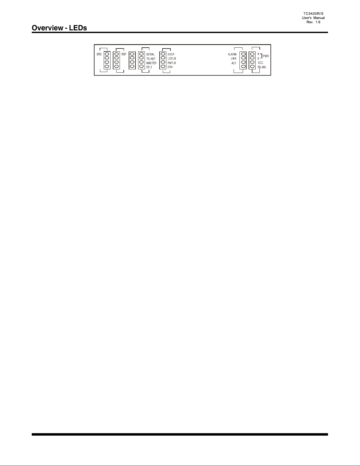
The TC3420 supports RS-232 interfaces (TxD and RxD). Seventeen LEDs are provided on the front panel
for all broadcast, response signals, Activity, Power and Link.
Power is 12VDC, optional 24VDC, -48VDC or 115/230VAC with an external power cube. Electrical
connectors are DB-9F, 10Base-T connectors are RJ-45F.
*Note: For future release.
- 4 -
1 2 3 4
- 5 -
"PWR A/B" LED: It is on when power is present at PWR A/B connector on rear panel.
"VCC" LED: It is on when adequate power is being derived from the power source.
"RS-485" LED:* It is on when the TC3420 is set for RS-485. (Internal SW2-8, On)
It is off when the TC3420 is set for RS-422. (Internal SW2-8, Off)
"Alarm" LED: It will light or flash under the following conditions.
1. Solidly lit when no Ethernet signal is detected. “LNK” LED will also flash.
2. Flashing when either the LOCLB, RMTLB or SIG GEN diagnostic mode is enabled.
“Link” LED: It is on when proper Ethernet signal is detected at the RJ-45 port. Flashing when no
Ethernet signal is detected at the RJ-45 port.
“ACT” LED (Activity): It will flash when data traffic is detected at the Ethernet port. It is normal
that the "ACT" LED will blink occasionally.
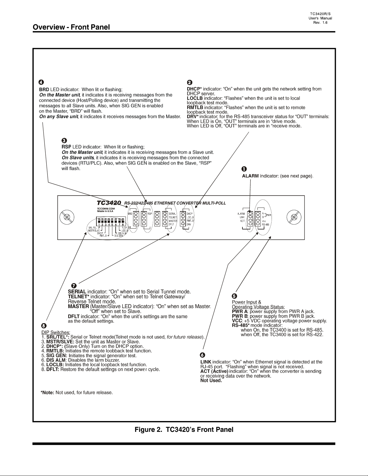
"DHCP" LED:* The DHCP option is available for slave unit only. The LED will flash when the unit is
getting the network information from the DHCP server and it is On when the unit gets the
information. The LED is Off for the master unit or when DHCP option is not set.
“LOCLB" LED (Local loopback): It flashes when the local loop back function is turn On.
“RMTLB" LED (Remote loopback): It flashes when the remote loop back function is turn On.
"DRV" LED: *It is on when the TC3420 is in “drive mode.
It is off when the TC3420 is in “receive mode.
“SERIAL” LED: It is on when the unit is set to Serial Tunnel mode.
“TELNET” LED: *It is on when the unit is set to Telnet Gateway or Reverse Telnet
mode.
*Note: Not used, for future release.

- 6 -
"MASTER" (Master/Slave) LED:
When "On", it indicates the TC3420 is set as Master.
When “Off", it indicates the TC3420 is set as a Slave.
When "Flashing", it indicates the IP is set to the factory default. Need to power cycle the unit
and set the DFLT dip switch back to the up position to make default IP effective.
“DFLT" LED (Default): When lit, it indicates the unit's IP is set to factory default:
Master: IP: 192.168.254.123, Subnet Mask: 255.255.255.0
Slave: IP: 192.168.254.124, Subnet Mask: 255.255.255.0
“BRD” LED indicator: When lit or flashing,
On the Master unit, it indicates it is receiving messages from the connected device (Host/Polling
device) and transmitting the messages to all Slave units. Also, when SIG GEN is enabled on the
Master, “BRD” will flash.
On any Slave unit, it indicates it receives messages from the Master.
“RSP” LED: When lit or flashing;
On the Master unit, it indicates it is receiving messages from a Slave unit.
On Slave units, it indicates it is receiving messages from the connected devices (RTU/PLC).
Also, when SIG GEN is enabled on the Slave, “RSP” will flash.
- 7 -
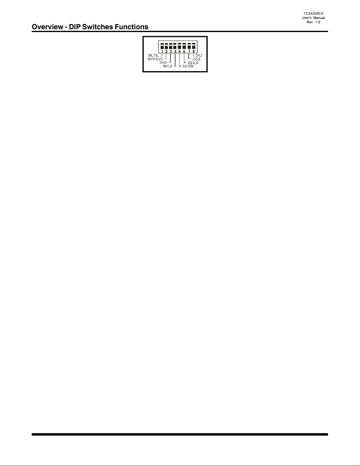
1. SRL/TEL*: Set the unit to Serial Tunnel mode (up position.)
Set the unit to Telnet Gateway or Reverse Telnet mode (down position.)
The changes apply on the next power cycle.
*Note: (Telnet is Not used, for future release)
2. MSTR/SLVE: Set the unit as Master (up position) or Slave (down position.) The
changes apply on the next power cycle, reset needed.
3. DHCP*: Turn on (down position) the DHCP option. (Slave only.) The changes
apply on the next power cycle, reset needed. Please refer to the "DHCP"
section for details.
4. RMTLB: Turns on the Remote Loop back test function.
5. SIG GEN: Signal Generator. Turns on the signal generator test function.
6. DISALM: Disable Alarm. It will disable the on board alarm buzzer (down position). It will
not clear the “alarm" condition and the "ALARM" LED will still be solid or
flashing during the “alarm” condition. However, the buzzer will be off and the dry
contact will be open.
7. LOCLB: Turns on the Local Loop back test function. Loop back the RS-232/422*/485*/
Analog* signal.
8. DFLT: Default. When set to the "On" (down position,) the unit will restore the default
settings on the next power cycle for either Master or Slave unit. It is used during
the initial setup or the IP address is lost.
If the “DFLT” switch is On, “MASTER” LED will flash.
Please refer to Chapter 3 on the manual for detail instructions.
*Note: Not used, for future release.
1 2 3 4
- 8 -
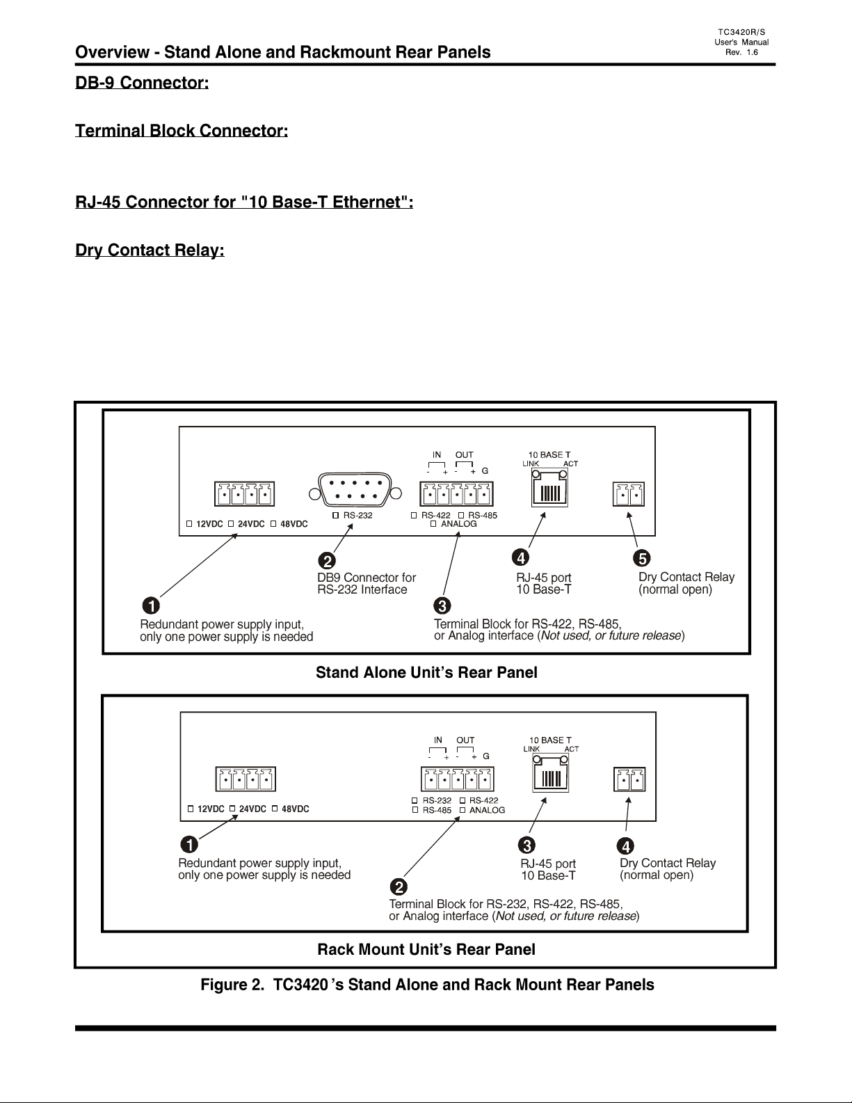
For Stand Alone units, connect this port for RS-232 connection.
Connect this port for RS-232, RS-422*, RS-485* or Analog* connection.
NOTE: For RS-232 connections, use the IN(-) pin for RxD, OUT(-) pin for TxD and G pin for signal ground.
Connect this port using a twisted pair Ethernet cable to the local network.
The Dry Contact Relay is normally in the “Open” position. It will force the relay to a "Close" position
under the following conditions:
1. Alarm is on (e.g. 10 Base-T signal lost).
Note: This function can be disabled by setting the front panel "DISALM" switch to on (down) position.
2. The dry contact relay will close during power up for a few seconds.
*Note: Not used, for future release.
PWR
A
PWR
B
ALM RLY
+ - + -
PWR
A
PWR
B
ALM RLY
+ - + -
- 9 -
Before unpacking any equipment, inspect all shipping containers for evidence of external damage caused
during transportation. The equipment should also be inspected for damage after it is removed from the
container(s). Claims concerning shipping damage should be made directly to the pertinent shipping agencies.
Any discrepancies should be reported immediately to TC Communications' Customer Service Department.
The TC3420 should be located in an area that provides adequate light, work space, and ventilation. Avoid
locating it next to any equipment that may produce electrical interference or strong magnetic fields, such as
elevator shafts or heavy duty power supplies. As with any electronic equipment, keep the unit from excessive
moisture, heat, vibration, and freezing temperatures.
Each TC3420 is powered by an external DC power adapter rated 12VDC @1.2A. The actual power
consumption is approximately 600mA.
Either a power adapter or power card can be utilized to supply the power to the TC3420. The power terminal
block connector can be plugged into any power jack on the rear panel. Since each TC3420 unit is equipped
with a power redundancy capability, the power LEDs on the front panel will light according to which power
jack it is connected to.
- 10 -
All units come with either Default Master or Default Slave settings. To properly restore the default settings,
please follow the following steps.
For Master:
1. Power off the unit.
2. Set the "DFLT" to on (down) position.
3. Set the unit as Master. "MSTR/SLVE" to up position.
4. Power up the unit and wait for 2 seconds.
5. Set the "DFLT" switch back to off (up) position.
Master IP: 192.168.254.123 Subnet: 255.255.255.0
For Slaves:
1. Power off the unit.
2. Set the "DFLT" to on (down) position.
3. Set the unit as Slave. "MSTR/SLVE" to down position.
3. Power up the unit and wait for 2 seconds.
4. Set the "DFLT" switch back to off (up) position.
Slave IP: 192.168.254.124 Subnet: 255.255.255.0
The "DFLT" LED on the front panel will turn on if the saved settings are the same as the default settings.
In order to configure the TC3420 that is, set to default, the user needs to use a PC with a web browser installed
Furthermore, the PC's IP address must be set within the range of 192.168.254.1 to 192.168.254.254, and with
a Network Mask of 255.255.255.0. If your PC does not have a compatible IP Address and Network Mask
,or you are not sure about the settings, please refer to the "PC Configuration" section for more detail.
To configure the TC3420, simply enter the IP address of the TC3420 in the Web browser's address box. For
Example, if the unit is set as Default Master, enter the following
http://192.168.254.123
(Attention: Contact your local area network administrator if you are unsure about the settings. Improper
settings may result in disruption of the existing network.)

- 11 -
Static IP:
Master unit's IP address must be Static. The IP address should be entered at the "IP address" field on the
"Settings" page.
Slave unit's IP address can be Static or Dynamic. For static IP setting, the IP address should be entered at
the "IP address" field on the "Settings" page.
Master Example:
TC3420: (Master)
TC3420: (Slaves)
Slaves Example:
- 12 -
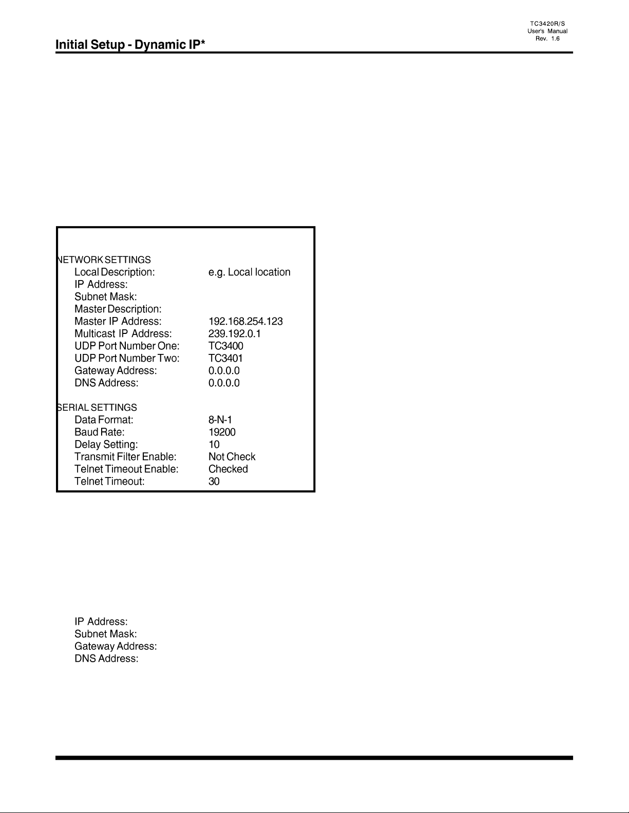
Dynamic IP (DHCP)*:
DHCP (Dynamic Host Configuration Protocol) option is for Slave unit only. It enables the Slave unit to get
a temporary or permanent IP addresses (out of a pool) from a DHCP server.
In order to use the DHCP function, there should be a DHCP server residing at the user's local area network.
If DHCP server is not available, the Slave unit's IP address must be Static. Please refer to the "Static IP"
section for more information.
Before you turn on the DHCP option, you need to enter the Master’s IP address at the “Remote IP” field
on the "Settings" page for the Slave Unit.
Example:
TC3420: (Slaves)
Please do the following after the "Master IP" has been set on the Slave units.
1. Power off the unit.
2. At the front panel, set "DHCP" DIP switch to on (down) position.
3. Power up the unit.
The following fields will be replaced by the data getting from DHCP server automatically, and user's data
will be ignored.
The “DHCP” LED will flash when the unit is obtaining the network settings from the DHCP server and the
LED turns solid after the unit gets the settings.
*Note: Not used, for future release.
- 13 -
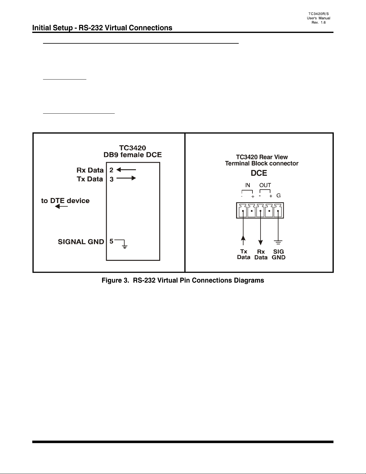
DB9 Female or Terminal Block RS-232 Virtual Pin Connections
The DB9 or Terminal Block RS-232 pin connections for the Master and Slave units are the same as depicted
on the diagrams below.
DB9 connector:
Pin 3, receives the transmitted data from the user's RS-232 device. Pin 2, transmits the data back to the user's
RS-232 device. Pin 5, is used for the signal ground.
Terminal block connector:
For RS-232 connections, use the IN(-) pin for RxD, OUT(-) pin for TxD and G pin for signal ground.

- 14 -
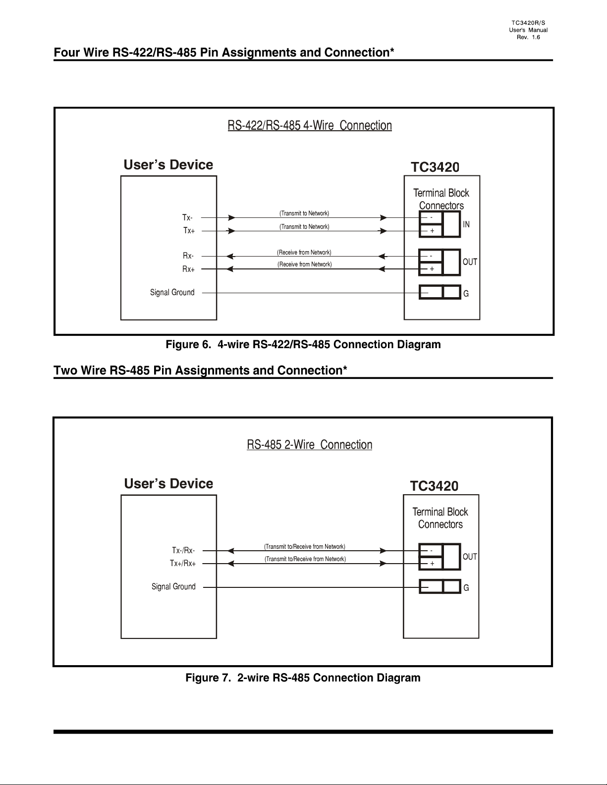
Two-wire RS-485 is a half-duplex operation, which means transmit and receive operations take turns; they
do not operate concurrently. From the user’s point-of-view, the channel is in receiving mode when no data
is transmitted from the remote unit. The local RS-485 transceiver will change to transmitting mode (Tx mode)
upon receiving the first bit of data from remote unit. The local RS-485 transceiver will stay in Tx mode until
a predetermined period (transition time; generally used by the customer's device) elapses after the last bit
is received from the remote unit. The TC3420 automatically adjusts internally for that specific transition time.
(See figure 4)
Four-wire RS-485 is a full-duplex operation, which means transmit and receive operations function
concurrently. From the user's point-of-view, both channels are in the receiving or transmitting mode at all
times. (See figure 5)
The RS-485 Driver/Receiver transition time is determined automatically by the TC3420 unit internally. The
local unit's RS-485 transceiver changes to transmit (Tx) mode upon receiving the first bit of data from the
remote unit. The transition time is the amount of time before the local unit's RS-485 transceiver will revert
to the high-impedance receiver mode after the last bit is received from the remote unit. The RS-485 transition
time automatically adjusts internally by the unit, according to the user's device timing.
*Note: Not used, for future release.
- 15 -
Terminal block connectors are provided on rear panel of the TC3420 for the RS-422*/RS-485* signal
connections. The pin assignments are illustrated below. Pins IN(-) & IN(+) are inputs and Pins OUT(-) &
OUT(+) are outputs.
Terminal block connectors are provided on rear panel of the TC3420 for the 2 wire RS-485 signal
connections. The pin assignments are illustrated below. Pins OUT(-) & OUT(+) are inputs/outputs.
*Note: Not used, for future release.

- 16 -
There are other eight DIP switches located at the PC board and can not be accessed from front panel. These
switches are usually only used during installation.
SW2-1: Not used.
SW2-2: Not used.
SW2-3: Not used.
SW2-4: Not used.
SW2-5: Not used.
SW2-6: Not used.
SW2-7: Not used.
SW2-8: Off: The TC3420 is setup for an RS-422* application.
On: The TC3420 is setup for an RS-485*, 2/4 wire application.
The ground connector should connect to the user's device's signal ground.
For an RS-485 application, the transition time is set automatically by the TC3420 once a baud rate is selected
from the pull-down field on figure 16 on page 23. The baud rate is set according to the customer's application
needs and the TC3420 will adjust accordingly. For example, if you know the async data baud rate of your
application is for a 9600 baud, then the TC3420 will adjust automatically.
A termination resistor is usually necessary for RS-422 and RS-485 applications. Without proper termination,
the error rate of data transmission may be high due to an “echo” effect on the electrical connection. With
the addition of a termination resistor at the beginning or end of the electrical bus, this echo effect is greatly
reduced. The termination resistors are 100 to 130 ohm resistors located on the interface module inside the
TC3420. Two jumpers, identified as board locations “W1” & “W5” control the termination resistance on each
unit. “W5” controls the resistance for the unit’s receiver, while “W1” controls the transmitter’s resistance.
Proper line termination is usually accomplished by leaving the “W5” jumper intact at both ends of the link.
There is no termination resistor required for RS-232 applications.
*Note: Not used, for future release.
- 17 -
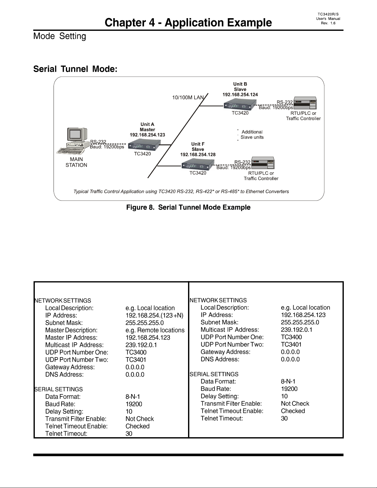
TC3420 can be used in three different modes (Serial Tunnel, Telnet Gateway* or Reverse Telnet*)
depending on the user's application.
In this mode, one Master TC3420 and (N) Slave units are used, and all of them are connected to serial RS-
232 devices.
1. Set one unit as a Master, and the others as Slaves using the front panel DIP switches. (Restart Require)
2. Set all units to Serial (SRL) mode using the front panel DIP switches. (Restart Require)
3. Use the Web Configuration Interface to enter the appropriate network and serial settings.
Example:
Slave TC3420s (Units B, C, D, etc) Master TC3420 (Unit A)
*Note: Not used, for future release.
- 18 -
1. Connect a computer and TC3420 on the same network.
2. Power up the TC3420 and the “LINK” LED should be on. (You can disable the alarm by
setting the "DISALM" to the down (on) position.)
3. Start your Web browser.
4. In the Address box, enter the IP address of the TC3420. For example, if the unit is set to
default Master, enter: http://192.168.254.123
If the unit is set to default Slave, enter: http://192.168.254.124
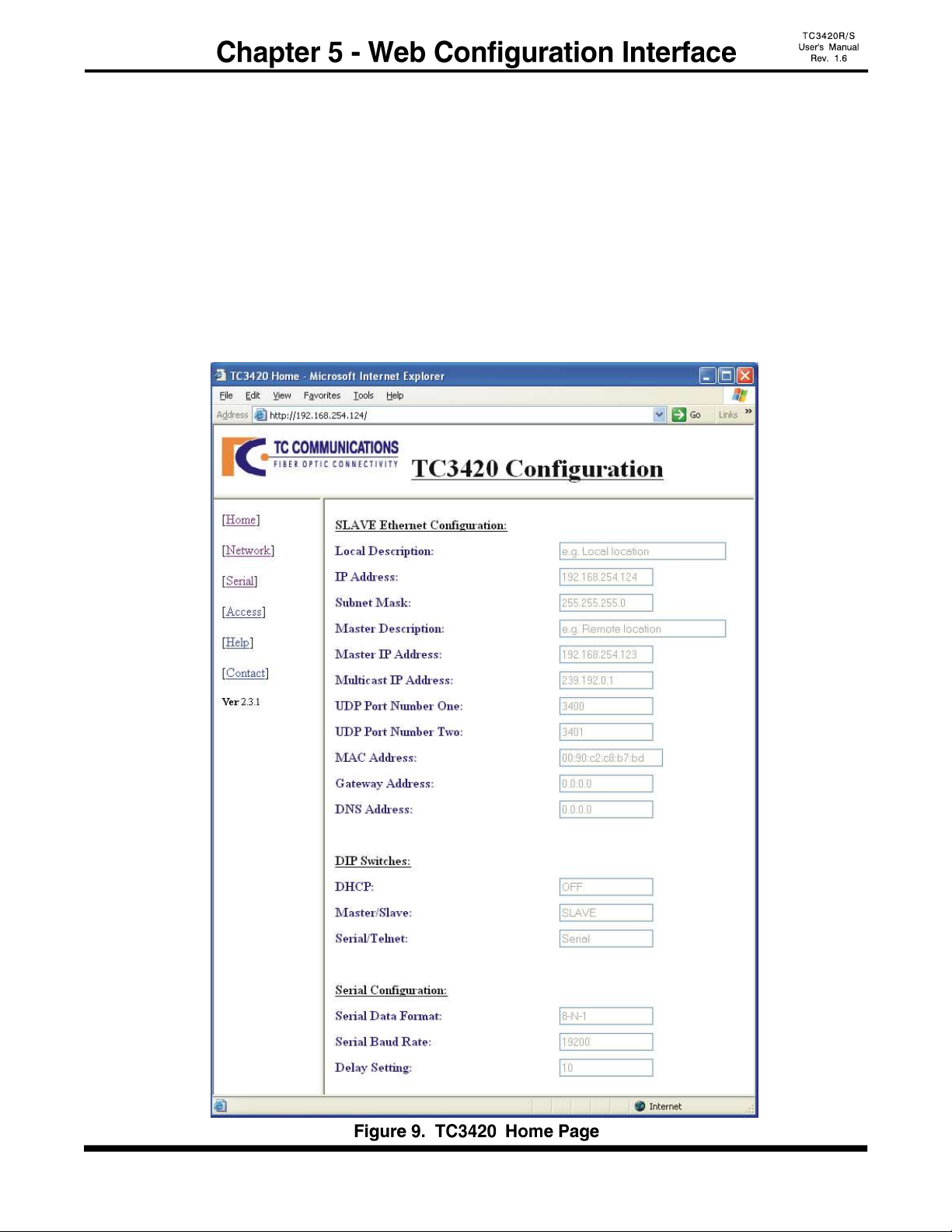
5. Once connected, you should see a dialog box as in figure 10, next page. Enter the username &
password and click enter, then you will see the following figure 9.
6. Click the links at the left of the page to navigate to the desired section.
Note: The Web Configuration Interface will not be accessible while the TC3420's are transmitting or
receiving serial data. Otherwise, it is accessible. (Such as when the units are idle)
(Please refer to "Testing & Trouble shooting" section, if not connected)

- 19 -
If you are being asked for a username and password on any of the pages, use the following:
Default user name: user
Default password: password
You can change the user name and password by clicking on the "Access" link at the home page.
Click the Browser's "Back" button to cancel all the changes.
Click the "Save" button to save the changes.
Click the "Reset" link to apply the new access setting at the "Access Configuration" page.
- 20 -
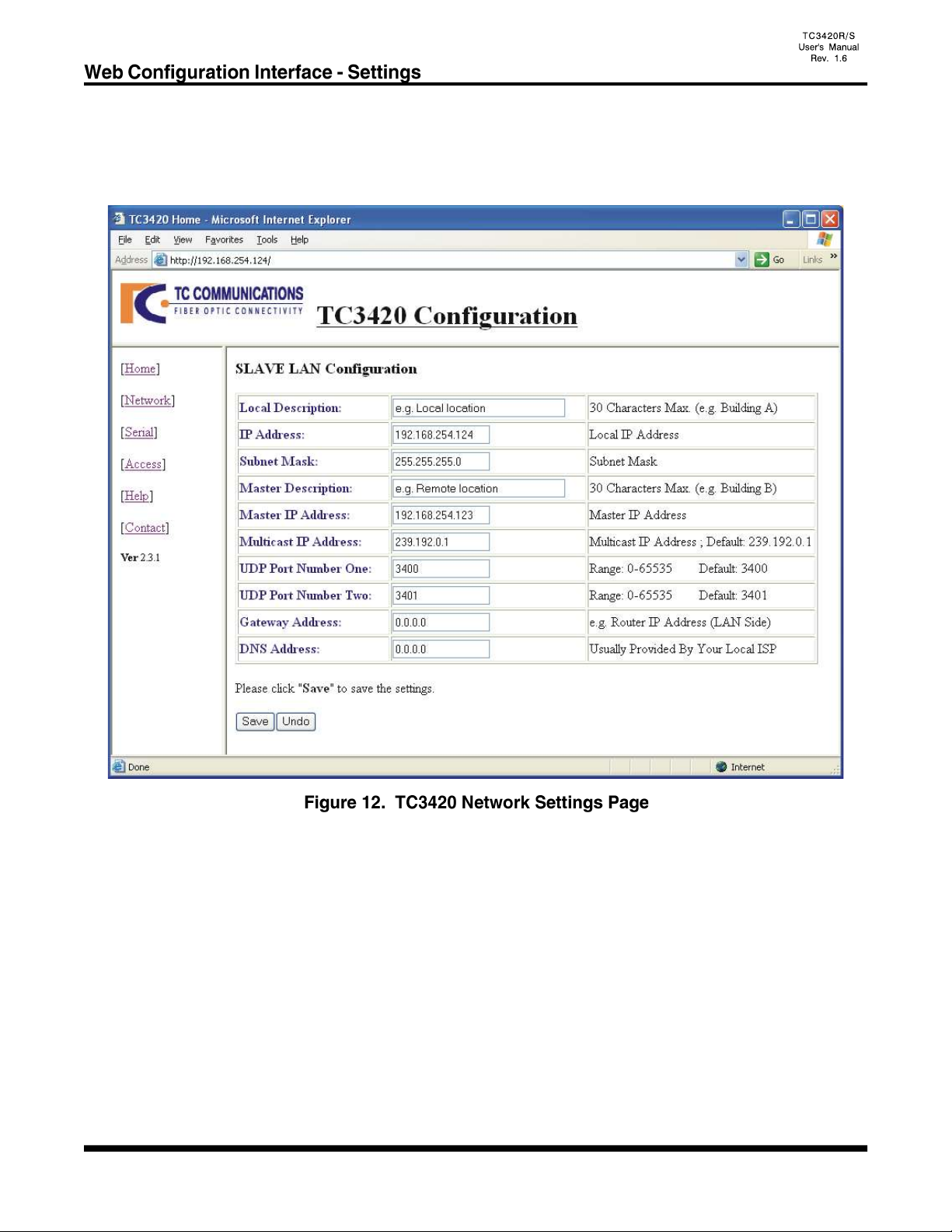
Click on the "Network" link at the home page and you should see the following "LAN Configuration" page.
Note: If the unit being configured is a Master, then the web pages will display "MASTER LAN Configuration"
and will be slightly different than those of the Slave units.
This manual suits for next models
1
Table of contents
Other TC Communications Media Converter manuals

TC Communications
TC Communications TC3026 User manual

TC Communications
TC Communications TC3005 User manual

TC Communications
TC Communications TC3025 User manual

TC Communications
TC Communications TC3006 User manual

TC Communications
TC Communications TC3212 User manual

TC Communications
TC Communications TC3301 User manual

TC Communications
TC Communications TC3020R User manual


