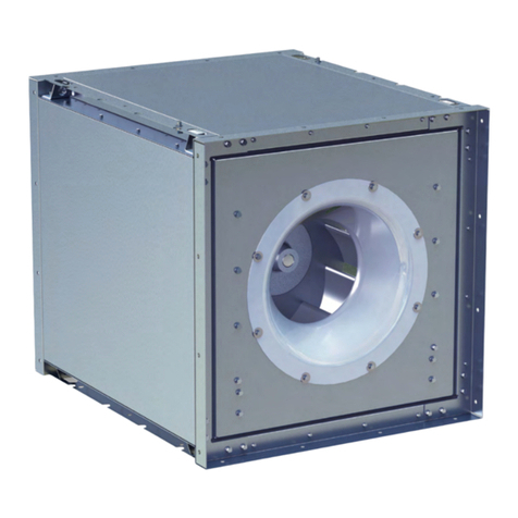
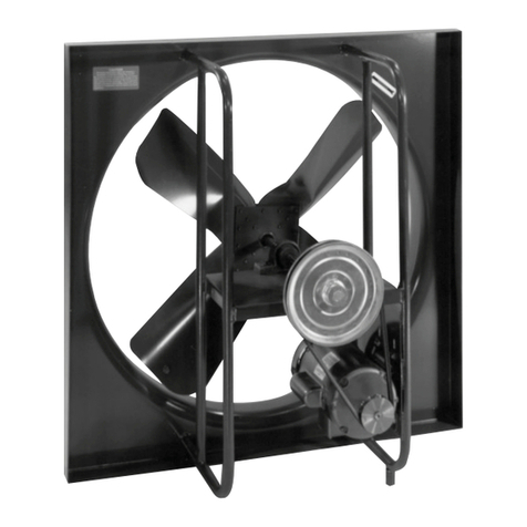
TCF ATAD Instruction manual

Introduction
The purpose of this manual is to provide instructions that
complement good general practices when installing or operating
fans manufactured by Twin City Fan & Blower. It is the responsibility
of the purchaser to provide qualified personnel experienced in the
installation, operation and maintenance of air moving equipment.
As always, follow good safety practices when installing,
maintaining and operating your air moving equipment. A variety
of safety devices is available. It is the user’s responsibility to
determine adequate safety measures and to obtain the required
safety equipment.
Shipping and Receiving
All Twin City Fan & Blower products are carefully constructed
and inspected before shipment to insure the highest standards of
quality and performance.
Compare all components with the bill of lading or packing list to
verify that the proper unit was received.
Check each unit for any damage that may have occurred in
transit. Any damage should be reported immediately to the carrier
and the necessary damage report filed.
Handling
Handling of all air moving equipment should be conducted by
trained personnel and should be consistent with safe handling
practices. Verify the lift capacity and operating condition of
handling equipment.
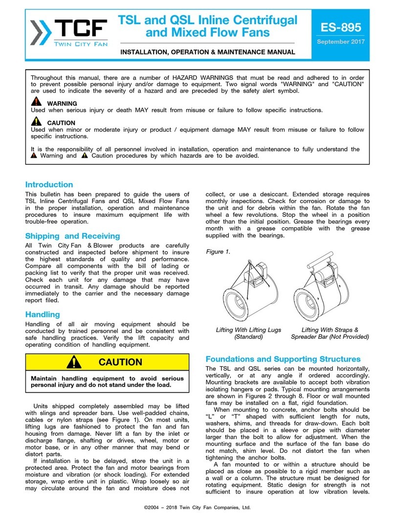
Units shipped completely assembled may be lifted with slings
and spreader bars. Use well-padded chains, cables or nylon straps.
On most units, lifting lugs are provided for attaching chains. Lift the
fan in a fashion that protects the fan and fan coating from damage.
Never lift a fan by the inlet or discharge flange, shafting or drives,
impeller, motor or motor base, or in any other manner that may
bend or distort parts.
If fan installation is to be delayed, store the unit in a protected
area. Protect the fan and motor bearings from moisture and
vibration (or shock loading). For extended storage, wrap entire unit
in plastic.
Extended storage requires monthly inspections. Check for
corrosion or damage to the unit and for debris within the fan.
Rotate the fan impeller a few revolutions. Stop the impeller in a
position other than the initial position. Grease the bearings every
month with a grease compatible with the grease supplied with the
bearings.
Foundations and Supporting
Structures
Typical mounting arrangements are shown in Figures 4 and 5 on
page 4. Floor mounted fans should be installed on a flat, level, rigid
concrete foundation. They require the mass of the foundation to be
at least three times that of the fan assembly. The plan area should
be no more than twice that required by the equipment. Foundations
with larger areas should have correspondingly larger mass. Anchor
bolts should be “L” or “T” shaped with sufficient length for nuts,
washers, shims and threads for draw-down. Each bolt should be
placed in a sleeve or pipe with a diameter larger than the bolt to
allow for adjustment. When the mounting surface and the surface
of the fan base do not match, shim or make allowance for grouting.
Do not distort the fan when tightening the anchor bolts.
©1991 – 2022 Twin City Fan Companies, Ltd.
ES-191
August 2022
Tubeaxial, Vaneaxial
& Duct Fans
INSTALLATION, OPERATION & MAINTENANCE MANUAL
Models
ATAD, ATAB, FPAC, FPDA, TCBS, TCPM, TCSM, TCVA, TCTA, TCVS, TCTS & TCVX
Maintain handling equipment to avoid serious personal injury.
CAUTION
Throughout this manual, there are a number of HAZARD WARNINGS that must be read and adhered to in order to prevent possible personal injury
and/or damage to equipment. Two signal words "WARNING" and "CAUTION" are used to indicate the severity of a hazard and are preceded by
the safety alert symbol.
WARNING
Used when serious injury or death MAY result from misuse or failure to follow specific instructions.
CAUTION
Used when minor or moderate injury or product / equipment damage MAY result from misuse or failure to follow specific instructions.
NOTICE
Indicates information considered important, but not hazard-related.
It is the responsibility of all personnel involved in installation, operation and maintenance to fully understand the
Warning and Caution procedures by which hazards are to be avoided.

2 Twin City Fan & Blower Engineering Supplement: ES-191
Fans mounted to or within a structure should be placed as
close as possible to a rigid member such as a wall or column. The
structure must be designed for rotating equipment; static design
for strength is not sufficient to insure proper operation. Supports
for suspended fans must be cross-braced to prevent side sway.
Structural resonance should be at least 20% from fan operating
speed. Vibration isolators should be used where applicable.
Any ducting should have independent support; do not use the
fan to support ducting. Isolating the fan from ductwork with flex
connections eliminates transmission of vibration. Fans handling hot
gases require expansion joints at both the inlet and discharge to
prevent excessive loads caused by thermal growth.
Fan Installation, Factory Assembled
Units
Follow proper handling instructions as given earlier.
1. Move the fan to the final mounting position.
2. Remove skid, crates and packing materials carefully.
3. Place vibration pads or isolation base on mounting bolts. Line up
holes in fan base with bolts.
4. Place fan on mounting structure. Carefully level the unit using
shims as required at all mounting hole locations. Bolt down the
unit.
5. Any grout may now be used. Bolt the fan in position before
applying grout. Do not depend upon grout to support rotating
equipment.
6. Continue with Operations Checklist.
General Motor Maintenance
The three basic rules of motor maintenance are: keep the motor
clean, keep it dry and keep it properly lubricated.
Blow dust off periodically (with low pressure air) to prevent the
motor from overheating.
Some smaller motors are lubricated for life. Motors less than 10
hp running about eight hours a day in a clean environment should
be lubricated once every five years; motors 15 to 50 hp, every 3
years; and motors 50 to 150 hp, yearly. For motors in a dusty or
dirty environment or running 24 hours a day, divide the service
interval by 2. If the environment is very dirty or high temperatures
exist, divide the service interval by 4. Lubrication requirements are
normally attached to the motor. Do not overlubricate.
Drive Maintenance
V-belt drives need periodic inspection and occasional belt
replacement. When inspecting drives, look for dirt buildup, burrs or
obstructions that can cause premature belt or drive replacement.
If burrs are found, use fine emery cloth or a stone to remove them.
Be careful that dust does not enter the bearings. Check sheaves for
wear. Excessive slippage of belts on sheaves can cause wear and
vibration. Replace worn sheaves with new ones. Carefully align
sheaves to avoid premature sheave failure.
Inspect the belts for wear. If fraying or other wear is observed to
be mostly on one side of the belts, the drives may be misaligned.
Reinstall the drives according to the following instructions:
1. Slip (do not pound) the proper sheave onto its corresponding
shaft.
2. Align sheaves with a straightedge
extended along the sheaves, just
making contact on the outside
perimeters of both sheaves. (See
Figure 1.)
3. Tighten sheave bolts.
4. Adjust the motor position to obtain
slack. Install and tighten belts. Use
a matched set of belts. Using a pry
will damage belts. Never use belt
dressing on any belts.
5. Tighten belts to proper belt
tension. Ideal tension is just
enough so that the belts do not slip under peak load. Recheck
sheave alignment.
6. New belts require a break-in period of operation so recheck the belt
tension after a few days of operation.
7. When replacing belts replace the entire set and follow the
procedure above.
Drive Adjustment
On small fans, the belt tension is adjusted by loosening the
four nuts on top of the motor plate and turning the four nuts
underneath the motor plate to achieve the proper belt tension.
Tighten the top four nuts to hold the motor plate in place. Care
should be taken to maintain drive alignment as described above.
Large fans use a pivoting motor mounting plate. Adjust the belt
tension by loosening the two nuts and bolts on the pivoting side of
the motor plate, and the nuts that hold the eyebolts to the motor
plate on the other side. Turn the nuts on the eyebolts that are
underneath the motor plate to achieve the proper belt tension and
then tighten the top nuts and the pivot side nuts and bolts. When
tightening the nuts that are on the eyebolts, take care to maintain
proper drive alignment.
Positioning the motor plate at too high of an angle may result
in the belts rubbing against the belt tube inside the fan. The motor
plate pivot bolt must be moved up or down to the next hole to keep
the drives centered in the belt tube. The ideal motor plate position
is perpendicular to the belt tube centerline.
Figure 1.
Sheave Alignment
Straightedge
Reversing the sheaves (placing the fan sheave on the
motor shaft) can overspeed the impeller and cause
structural failure.
CAUTION

Twin City Fan & Blower Engineering Supplement: ES-191 3
Bearing Lubrication
Proper lubrication of belt drive bearings helps assure maximum
bearing life. All fans are equipped with decals indicating relubrication
intervals for normal operating conditions. However, conditions at
every installation are different and the frequency of relubrication
should be established accordingly. Figure 2 shows the relubrication
schedule for ball bearings. Figure 3 shows the relubrication
schedule for solid pillow block spherical roller bearings.
Lubrication intervals should be doubled on fans with vertical
shafts.
On high moisture applications, the relubrication frequency may
need to be doubled or tripled to adequately protect the bearings.
Carefully replace the joint sealant under the bearing access cover
whenever the bearings on high moisture fans are serviced.
Observation of the condition of the grease expelled from the
bearings at the time of relubrication is the best guide as to whether
regreasing intervals and the amount of grease added should be
altered.
Greases are made with different bases. There are synthetic base
greases, lithium base, sodium base, etc. Avoid mixing greases with
different bases. They could be incompatible and result in rapid
deterioration or breakdown of the grease.
All bearings are filled with a lithium based grease before leaving
the factory. When the fans are started, the bearings may discharge
excess grease through the seals for a short period of time. Do not
replace the initial discharge because leakage will cease when the
excess grease has worked out. Bearings have a tendency to run
hotter during this period and should not be a cause for alarm unless
it lasts over 48 hours or gets very hot. When relubricating, use a
sufficient amount of grease to purge the seals. Rotate bearings
during relubrication where good safety practice permits.
Impeller and Shaft Maintenance
The buildup of material on axial flow impellers can adversely
affect fan performance. While fans that handle clean, fresh air
seldom need cleaning, occasionally check fans used for industrial
purposes for material buildup on the impeller. This material can
come off in large chunks, throwing the impeller out of balance.
Clean the impeller and, on vaneaxial fans, the turning vanes; when
appropriate, apply new coatings.
If the impeller is removed for any reason, make sure that it
is securely attached to the shaft before restarting the fan. If the
impeller is attached to the shaft by means of a Trantorque®bushing,
use the tightening torque values shown in Table 1.
Table 1.
TRANTORQUE®SHAFT SOCKET TORQUE TORQUE
SIZE DIA. SIZE (IN. LBS.) (FT. LBS.)
7⁄8
7⁄811⁄2 850 71
11⁄811⁄813⁄41550 130
13⁄813⁄82 1700 141
15⁄815⁄821⁄42800 233
17⁄817⁄821⁄23900 325
21⁄821⁄823⁄45300 440
23⁄823⁄83 5600 470
27⁄827⁄831⁄26600 550
Note: These torque values are to be obtained with a calibrated torque wrench. DO
NOT apply any lubricant to any part of the Trantorque®hub. DO NOT use an anaerobic
thread adhesive such as Loctite®on the threads.
Figure 2. Ball Bearing Relubrication Schedule
Figure 3. Solid Pillow Block Spherical Roller Bearing
Relubrication Schedule
*Suggested lubrication interval under continuous operation in adverse loading or with
elevated temperatures. For operation less than 24 hours per day or under ideal conditions,
lubrication frequency may be reduced. Relubricate while running, if safety permits, until
some purging occurs at seals. Adjust lubrication frequency depending on condition of
purged grease. Hours of operation, temperature and surrounding conditions will affect the
relubrication frequency required.
1. Lubricate with a high quality NLGI No. 2 lithium-base grease having rust inhibitors and
antioxidant additives, and a minimum oil viscosity of 500 SUS at 100°F (38°C). Some
greases having these properties are:
Shell - Gadus S2 V100 2 Mobil - Ronex MP
Mobil - Mobilith SHC100 Mobil - Mobilith SHC220
2. Lubricate bearings prior to extended shutdown or storage and rotate shaft monthly
to aid corrosion protection.
3. Any lubrication requirements noted on the general assembly drawing supersede
requirements found here.
Fans with Unit Roller Bearings
Relubrication Schedule (Weeks)*
Spherical Roller Bearing - Solid Pillow Blocks
Shaft DIA Speed (RPM)
500 1000 1500 2000 2500 3000 3500 4000 4500
1⁄2" thru 17⁄16"
(13 – 35) 644211110.5
111⁄16" thru 23⁄16"
(40 – 55) 4 2 1.5 1 0.5 0.5 0.5 0.5 0.5
27⁄16" thru 37⁄16"
(60 – 85) 3 1.5 1 0.5 0.5 0.25 0.5 – –
315⁄16" thru 415⁄16"
(100 – 125) 2.5 1 0.5 0.25 – – – – –
WARNING
1. This equipment must not be operated without proper guarding
of all moving parts. While performing maintenance be sure
remote power switches are locked off. See AMCA Publication
410 for recommended safety practices.
2. Before starting: Check all set screws for tightness and rotate
impeller by hand to make sure it has not moved in transit.
*Suggested lubrication interval under continuous operation in adverse loading or with
elevated temperatures. For operation less than 24 hours per day or under ideal conditions,
lubrication frequency may be reduced. Relubricate while running, if safety permits, until
some purging occurs at seals. Adjust lubrication frequency depending on condition of
purged grease. Hours of operation, temperature and surrounding conditions will affect the
relubrication frequency required.
1. Lubricate with a high quality NLGI No. 2 lithium-base grease having rust inhibitors and
antioxidant additives, and a minimum oil viscosity of 500 SUS at 100°F (38°C). Some
greases having these properties are:
Shell - Gadus S2 V100 2 Mobil - Ronex MP
Mobil - Mobilith SHC100 Mobil - Mobilith SHC220
2. Lubricate bearings prior to extended shutdown or storage and rotate shaft monthly to
aid corrosion protection.
3. Any lubrication requirements noted on the general assembly drawing supersede
requirements found here.
Fans with Ball Bearings
Relubrication Schedule (Weeks)*
Ball Bearing Pillow Blocks
Shaft DIA Speed (RPM)
500 1000 1500 2000 2500 3000 3500 4000 4500
1⁄2" thru 111⁄16"
(13 – 45) 665332221
115⁄16" thru 27⁄16"
(50 – 60) 654221111
211⁄16" thru 215⁄16"
(65 – 75) 5432111––
37⁄16" thru 315⁄16"
(90 – 100) 4 3 2 1 1 – – – –

4 Twin City Fan & Blower Engineering Supplement: ES-191
Structural Maintenance
All structural components or devices used to support or attach the
fan to a structure should be checked at regular intervals. Vibration
isolators, bolts, foundations, etc., are subject to failure from
corrosion, erosion and other causes. Improper mounting can lead
to poor operation characteristics or fan fatigue and failure.
Check metallic components for corrosion, cracks or other signs
of stress. Concrete should be checked to insure the structural
integrity of the foundation.
Operation Checklist
Verify that proper safety precautions have been followed:
□Electrical power must be locked off.
Check fan mechanism components:
□Nuts, bolts and set screws are tight.
□Mounting connections are properly made and tightened.
□Bearings are properly lubricated.
□Impeller, drive and fan surfaces are clean and free of debris.
□Rotating assembly turns freely and does not rub.
□Sheaves are on the correct shafts, properly aligned and properly
tensioned.
Check fan electrical components:
□Motor is wired for proper supply voltage.
□Motor size is sufficient to power the rotating assembly.
□Motor is properly grounded.
□All leads are properly insulated.
Trial “bump”:
□Turn on power just long enough to start assembly rotating.
□Check rotation for agreement with rotation arrow.
□Listen for any unusual noise.
Run unit up to speed:
□Bearing temperatures <180°F are acceptable after one to two
hours of operation.
After one week of operation:
□Check all nuts, bolts and set screws and tighten if necessary.
□Readjust drive tension if necessary.
Figure 5. Vertical Mounting Arrangements
Airflow Airflow
Airflow Airflow
4 Mounng
Holes
AA
Discharge Down
Floor Mount
Discharge Down
Ceiling Hung
Discharge Up
Floor Mount
Discharge Up
Ceiling Hung
View A
NOTE: Fan can be supported with anchor bolts, vibration isolators or
support rods.
Figure 4. Horizontal Mounting Arrangements
Support
Rods
Suspension
Clips
2 Support
Legs
4 Nuts &
Washers 4 Anchor
Bolts
Fan
Support Rods
Horizontal with
Suspension Clips
Horizontal with
Support Legs
Duct Supported
Installaon

Twin City Fan & Blower Engineering Supplement: ES-191 5
Blade Adjustment on Adjustable
Pitch Vaneaxial Type TCVX
Blade Angle Adjustment
The blades are set at the factory to the blade angle that gives the
performance specified on the order. This angle should be checked
prior to start-up. The patented impeller construction uses friction
and centrifugal force to hold the blades in place. No disassembly of
the impeller is required to change the blade angles. If it is necessary
to change the blade angle, the following procedure should be used:
1. Work safely. Make sure that proper safety precautions have
been followed. Electrical power must be locked off.
2. The adjustment can be made through the inlet on open inlet
fans. On fans with ducted inlets, open the impeller area access
door.
3. Place adjustment tool around end of blade (see Figure 6, to
the right). If necessary, apply “cheater bar” around the 11⁄4"
diameter end for additional leverage.
The blades can be turned by hand on open inlet fans. If
additional leverage is needed, place a wrench on the leading
edge of the blade near the hub. Take care not to mar the surface
of the blade.
4. Prior to adjusting the blade angle, check the performance data
to insure that the motor will not overload.
5. Turn blade to desired angle. See Figure 6. There is an indicator
mark on the hub. Align the Vernier index line on the blade with
the indicator mark on the hub. The Vernier has the characters
3, 4 and 5 with gradation lines in between. (Note: Character
3 is 30°, 4 is 40°, 5 is 50°.) Each gradation is 2.5°. The blade is
adjustable between 25° and 50°.
6. Friction and centrifugal force will hold the blade at the set angle.
No additional adjustment is necessary.
7. Adjust all blades to the same angle.
8. Close the impeller area access door before operating the fan.
5
4
3
Tool AS-14093
Blade Tip
Cheater Bar
Hub
Blade
Leading Edge
Detail "X"
Blade
Trailing Edge
Detail “X”
Vernier Index Line
(Blade As Shown
Is Adjusted To 35°)
Figure 6.
25.0"
0.50"
0.25"
5
4
3
Blade
Hub

6 Twin City Fan & Blower Engineering Supplement: ES-191
Electrical Components
Motor wired for proper voltage and starter
Motor grounded
Appropriate starter and heaters
Leads are properly insulated
Accessories wired per instructions supplied.
Energize
Energize motor long enough to start assembly
rotating, shut down
Verify direction of impeller rotation, rewire if
necessary Note: Refer to Impeller Rotation section
Run the fan up to speed
Check for excess vibration and listen for unusual
noise. Refer to the Vibration Guidelines table in the
Troubleshooting Guidelines section for vibration
limits.
Bearing temperatures should stabilize after a few
hours. Less than 200°F
Note: Use sense of smell to identify possible electrical, belt issues.
After one Week
Verify bolt tightness.
Verify belt tension and adjust as necessary
Initial Fan Check
Inspect fan for damage
Check foundation
Is the fan shimmed
Are the bolts tight
Check to see if the fan is distorted
Note: Applies to direct or isolation mount.
Check fan interior for debris and standing water
Fan Impeller
Impeller clearance checked
Impeller overlap checked
Fasteners tight
Impeller rotates freely
Springs (if equipped)
Springs adjusted properly
Flex joints allow movement
Electrical conduit allows movement
Bearings
Bearings aligned
Bearings greased
Note: Rotate while greasing
Set screws tight (if equipped)
Lube Lines
Lube lines been charged with grease prior to
connecting to bearings
V-Belts (if equipped)
V-belt drives aligned
Sheaves retightened
Belt tension correct
Motor bolts retightened
Accessories
Guards installed correctly, do not rub
VIV/damper opens freely (if equipped)
Other accessories per drawing
Installation/Start-up Checklist
Become familiar with the equipment by looking at the fan assembly drawing for
special instructions and accessories.
Verify that proper safety precautions have been followed.
Electrical power must be locked off.
WARNING
Serial Number:
Completed By:
Date Completed:
NOTICE
Always observe site specific and regulatory safety precautions.

Twin City Fan & Blower Engineering Supplement: ES-191 7
This page intentionally left blank.
This manual suits for next models
11
Table of contents
Other TCF Fan manuals
Popular Fan manuals by other brands

Viessmann
Viessmann Vitovent 300-W Installation and service instructions
Hunter
Hunter 28081 Parts guide

Bastilipo
Bastilipo Tenerife instruction manual

Kichler Lighting
Kichler Lighting Compass 300322 instruction manual
Platinum
Platinum FD-30M instruction manual

Kendal Lighting
Kendal Lighting AC-24060 installation instructions

Mitsubishi Electric
Mitsubishi Electric Lossnay LGH-15RX5-E operating instructions

Casablanca
Casablanca C19xxxK owner's manual
Remington Solar
Remington Solar SF-WF40-BLK manual
Harbor Breeze
Harbor Breeze 0883783 manual
Genesis
Genesis A1WINDOWFAN instruction manual

Black & Decker
Black & Decker BDHV-5018 instruction manual

