TCi 376600 User manual

1
Part # TCI-9006
Revised 9/6/2016
Toll Free: 1.888.776.9824
www.tciauto.com
TCI®Automotive
151 Industrial Dr.
Ashland, MS 38603
Phone: 662.224.8972
TCI®376600
Universal TCC Lock-Up Kit for 700R4 and 2004R
This kit enables hands-free, automatic activation of the Torque Converter Clutch (TCC) along with the
option of manual control.
TCI®376600 Kit Contains:
Qty. Description
One (1) Internal Wiring Harness
One (1) External Wiring Harness
One (1) Vacuum Switch
One (1) Fourth Gear Pressure Switch - 2 terminal, N.O.
Two (2) Splice Connectors
One (1) #4 Machine Screw
Step 1 —Drain transmission oil pan. You will need a pan to catch fluid. Remove transmission oil pan
bolts. When removing bolts, remove so pan will not drop completely off. Instead it will be held in
place so that one side will allow the fluid to be drained. After the fluid has drained, remove the rest of
the bolts and pour out the remaining fluid. If your transmission did not come with a drain plug, you
may want to install a TCI®805800 universal drain plug kit into your pan now that you have the pan
off. Remember To Dispose Of Used Oil In An Environmentally Safe Way.
Step 2 —Remove original internal wiring
harness. Carefully disconnect the wire
connectors from the switches. Remove the wires
from the clips and unplug the wiring harness
from the connector near the detent roller spring.
Pry connector tab away from the plug and pull
the plug down. Do not pull on the wires.
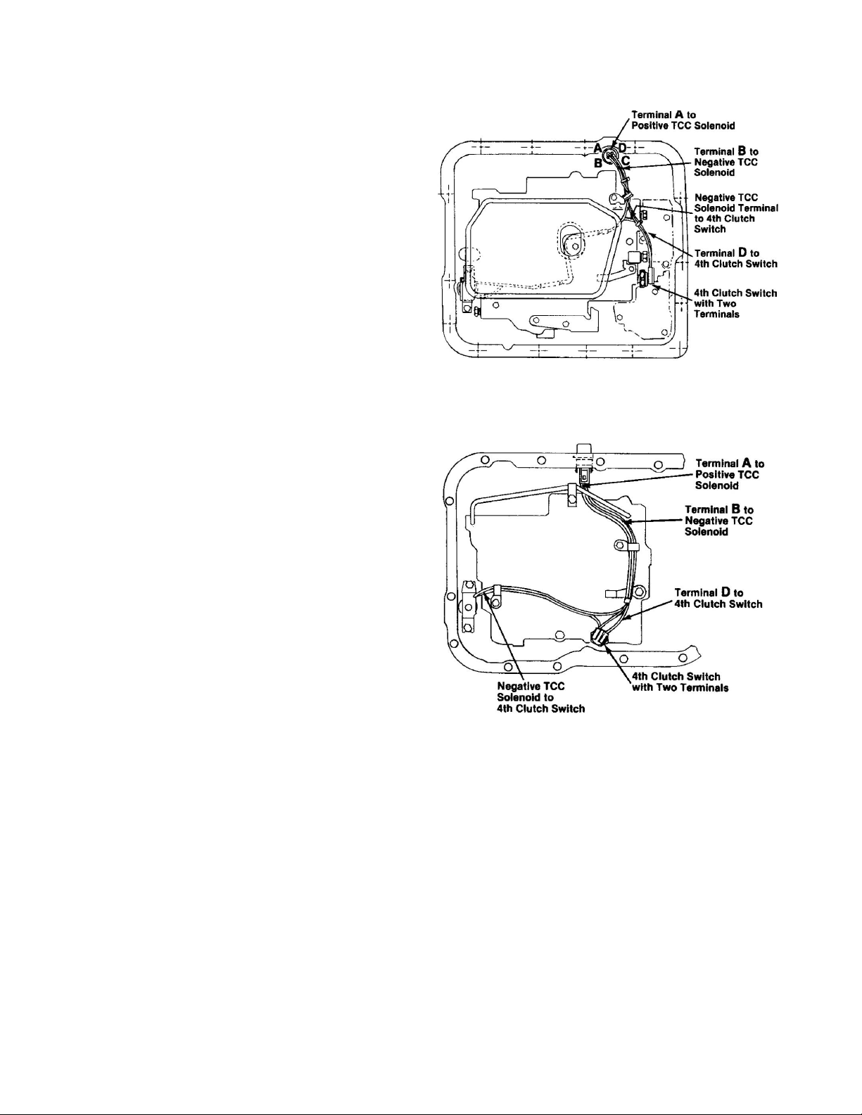
Step 3 —Based on your application, find the
wiring diagram to determine the proper fourth
gear pressure switch location. See Figures 1, 2
and 3. Install the switch and torque to 8 foot-
pounds. Additional OEM switches may be left
in place even though they will not be utilized.
INSTRUCTIONS
Figure 1: 700R4 Street/Strip Wiring Diagram
2
Part # TCI-9006
Revised 9/6/2016
Toll Free: 1.888.776.9824
www.tciauto.com
TCI®Automotive
151 Industrial Dr.
Ashland, MS 38603
Phone: 662.224.8972
Step 4 —Installation of TCI Wiring Harness:
Most applications will accept the OE solenoid.
All two-wire solenoids are acceptable. If you
have a solenoid with only one wire, it cannot be
used. You may purchase the proper solenoid
from GM, part number 8654126. Using your
OEM, two-wire solenoid, cut both wires
allowing about 2-1/2" for splicing to the TCI®
wiring harness. (Note: Look closely at the black
plastic connector on the new TCI®harness.
Notice that each terminal position is labeled A
through D. This instruction will refer to these
positions so that your connections are made
properly.) To connect your solenoid to the TCI®
wiring harness, use the splice connectors
provided. Connect the positive solenoid wire to
the wire going to Terminal A on the wiring
harness, then connect the negative solenoid wire
to the harness wire going to Terminal B.
Install wiring harness and solenoid into the
transmission. Torque the solenoid bolts to 8
foot-pounds. Plug the two pressure connectors
into the fourth pressure switch on the valve
body. Reinsert the black plastic transmission
case connector into the transmission. If you are
working with a 700R4, you may want to transfer
your OEM plastic wire retainer from your
factory wiring harness to the TCI®wiring
harness in order to keep wires neatly in place.
Step 5 —Figure 4 shows how the external
wiring harness is intended to be connected. To
use the #4 machine screw to retain the switch to
the case, a new 3/32" hole must be drilled in the
mount boss. If floor pan clearance is a problem
then secure the ring terminal to the mount boss on the case to provide a good ground and secure the
switch to the wiring harness with electrical tape so that it does not bang around. Some 2004R’s may
have an interface problem between the TCI®harness and the OEM case connector. To correct this
problem, obtain case connector number 8634383 from a GM dealer. This will allow the TCI harness to
snap into place. Using 18-gauge wire, run a 12-volt source to the red wire on the harness (Terminal A).
Connect the vacuum switch to a ported vacuum source on the carburetor or throttle body. (If you find
that the TCC operation is erratic in your application, then you may try moving the vacuum source to
the manifold.) The TCC is now set to engage automatically in 4th gear only when engine vacuum is
Figure 2: 700R4 Competition/Full Manual
(376010 valve body) Wiring Diagram
Figure 3: 2004R Street/Strip or
Competition/Full Manual
(386010 valve body) Wiring Diagram

3
Part # TCI-9006
Revised 9/6/2016
Toll Free: 1.888.776.9824
www.tciauto.com
TCI®Automotive
151 Industrial Dr.
Ashland, MS 38603
Phone: 662.224.8972
greater than 8-10 inches. The converter clutch will
release when the transmission is down shifted out
of 4th gear or engine vacuum falls due to increased
throttle.
Step 6 —Refer to Figure 5. If you desire more
control over the TCC you have a few options:
Option 1 will allow you to manually lock up the
torque converter in 2nd gear, 3rd gear and/or 4th
gear by running the green wire (Terminal B) to a
grounded dash mounted toggle switch.
Option 2 is for drivers that may want to shut down
the TCC system through a second dash mounted
toggle switch between to the red wire on the TCI®
external harness (Terminal A) and the switched 12-
volt source. Now, you may manually turn the lock
up system completely on and off.
Option 3 is for those who desire immediate release
of the TCC when braking. For this, you'll need an
OEM brake pedal switch with a normally closed
circuit. Run your switched 12-volt source through
the brake switch and then to the red wire on the
TCI®external harness.
Step 7 —Reinstall Transmission Pan: Install a
new filter. Remove any pan gasket material that
may have been left on the transmission case/pan
during pan removal. Always replace transmission
pan gasket when reinstalling pan. Refill
transmission with ATF being sure not to overfill.
Red wire -
switched
12V
Figure 4: External Wiring Configuration
Green wire -
optional; see
Step 6
Black wire -
through switch
to ground
D
B
A
4th clutch switch
(N.O.)
TCC Solenoid
(N.O. Oil Path)
Engine Vacuum
Switch (N.O.)
BLK
GRN
RED
Optional Switch 2 & 3
Optional Switch 1
Switched 12V
Figure 5 - Electrical Schematic for
All 700-R4s & 200-4Rs

4
Part # TCI-9006
Revised 9/6/2016
Toll Free: 1.888.776.9824
www.tciauto.com
TCI®Automotive
151 Industrial Dr.
Ashland, MS 38603
Phone: 662.224.8972
Frequently Asked Questions About 376600
Q: Will this kit work in conjunction with my OEM computer (ECM)?
A: With the 376600 installed properly your ECM will no longer interface with the transmission. Do
not attempt to plug the OEM wiring harness from your computer into the transmission with this kit
installed! It is not compatible! The ECM will continue to control the vital engine functions even
though it is no longer controlling your torque converter lockup.
Q: How do I know which wire is which on the new TCI®internal wiring harness?
A: If you look closely at the sides of the black connector that is holding all three wires you will see the
letters A, B, C and D at each wire location. These correspond to the wiring diagrams shown in the
376600 instruction sheet.
Q: I want to install this on a 1993 700-R4 but the connectors don’t match. What can I do?
A: This kit can work on a 1993 700-R4 with some additional ingenuity. Using a paper clip or similar
piece of wire, the individual wires can be removed from the plastic connectors by depressing the lock
tabs on the crimped terminal inside the connector. Transfer the wires from the TCI®wiring harness to
your 5 terminal connectors. As long as you transfer the wires from TCI®location A to your location A,
etc. there will be no problems. Also, note that if your wire A runs directly from the case connector to
the solenoid positive terminal without first going through a pressure switch than it can simply be left in
place because that is how the 376600 is wired as well.
Q: What do I do with the other pressure switches that are on my valve body?
A: The simple thing to do is just leave them in place even though they are not hooked up. They cannot
be removed unless you replace them with 1/8" pipe thread plugs.
Q: What do I do with the extra green wire on the external wiring harness?
A: As mentioned in Step 5 the green wire is a supplemental ground for the electric circuit and it is
strictly optional. By routing this through a dash mounted toggle switch you can override the fourth
clutch pressure switch and the vacuum switch and force lockup in second, third or fourth gears
manually. One example would be if you were towing in drive (third) and would like to utilize the
torque converter clutch. Remember that this is on the ground side of the circuit. Putting 12 volts on
this wire may short out your solenoid.
Q: If I have a one-wire solenoid, why can’t I use it?
A: The TCI®wiring setup does all of the switching on the ground side of the circuit. A one wire
solenoid is self-grounded and therefore not able to be wired into the TCI®376600.
Q: How do I know if my solenoid is good?
A: The first step in determining if your solenoid is serviceable is to test the electric coil. You will need
a simple test meter that can check resistance. Resistance is measured in Ohms and uses the following
symbol: . This is important to check because some of the most frequent problems arise from the use
of a solenoid that is electrically shorted out internally. A good solenoid will measure between 24.5
and 26.5. If you get a reading outside this range then the solenoid should be replaced. If the solenoid

5
Part # TCI-9006
Revised 9/6/2016
Toll Free: 1.888.776.9824
www.tciauto.com
TCI®Automotive
151 Industrial Dr.
Ashland, MS 38603
Phone: 662.224.8972
checks well, electrically, it can also be tested for mechanical function. With no power applied, you
should be able to blow air through the end of the solenoid. Then put power to the solenoid (12V to
positive side & ground the negative side) and the coil should force the checkball onto its seat,
preventing air from going through the solenoid. Also be sure to inspect the condition of the rubber 0-
ring on the end of the solenoid. It needs to provide a good seal inside the bore where it is housed.
Replace if necessary.
Q: I checked my solenoid but I keep blowing fuses when the system tries to activate. What should
I do?
A: If the solenoid is not internally shorted then the problem is most likely a pinched or exposed wire
on the positive side of the circuit. An easy method to check for a short in the system without first
removing the transmission oil pan is to disconnect your power supply from the red wire on the TCI®
external wiring harness and measure the resistance between the red and the green wire. It should be
between 24.5and 26.5. If you get a reading of 0, then the short is located within the oil pan. If the
reading is OK, check the resistance from your power supply to ground. There should not be any
continuity between your power source and ground.
Q: The system is functioning properly as far as I can tell, but the torque converter won’t lock up.
What’s wrong?
A: The wiring harness and solenoid only comprise a fraction of the entire lock-up system on your
transmission. In order for the system to work properly the converter clutch valve in the pump must be
operable, the friction lining and apply piston in the torque converter must be in working order, the 0-
ring on the end of the input shaft must be in good condition and some valve bodies even have an
additional converter clutch valve in them as well which must be functioning.It is possible for anyone of
the aforementioned components to malfunction causing the lock-up system not to work. Have a
qualified technician help if you suspect something else is wrong.
Q: What is the setting on the vacuum switch?
A: The vacuum switch comes factory preset to close at 8 - 10 inches of Hg. This means that in order
for the solenoid to be activated the switch must get 8 - 10 in. Hg. or higher. If you find that the torque
converter lockup experiences "busyness" (shuttles on and off rapidly) at cruise conditions it is probably
because your engine vacuum under that particular condition is right where the switch turns on and off.
This can be verified with an engine vacuum gauge.
If you have a "busyness" problem the switch can be reset. Remove the switch from your transmission.
Locate the small dimple in the center of the switch on the side marked "World Magnetics". Using a
1/8" drill bit, by hand, gently remove the potting material to expose the adjustment screw. Using a
small Allen wrench, turn the adjustment screw: clockwise to raise the vacuum required to close the
switch and counterclockwise to lower it. The adjustment screw is sensitive so it does not need to be
moved very much to make a difference. A small dab of silicone will seal the adjustment screw when
you are done.
Q: Can I activate the torque converter clutch in low gear?
A: No. The transmissions are designed by General Motors to enable the lock-up system only after the
second gear shift has occurred.
Other TCi Industrial Equipment manuals


