TCL TRF-436W User manual

Refrigerator Service Manual
TRF-436W
TCL Home Appliances (HeFei) Co., Ltd.

Contents
1.Product Instruction
2.Exploded View of Product Structure
3.Refrigeration system
4.Electrical system
5.Product operation rules
6.Maintenance instructions
7.Guidelines for disassembly of some structural parts

1.Product Instruction
The appearance and modeling is as follows:
•3-gear temperature change
•Computer temperature control
•R600a refrigerant
•Variable frequency
Product features:

2.Exploded view of product structure

Complete-machine parts list
S/N
Description
Qty.
1
Right Door Assembly of Refrigerator Compartment
1
2
Left Door Assembly of Refrigerator Compartment
1
3
Upper Door Assembly of Freezer Compartment
1
4
Lower Door Assembly of Freezer Compartment
1
5
Freezer Door Seal/Cold-Resistant High-Elastic PVC
1
6
Freezer Door Seal/Cold-Resistant High-Elastic PVC
1
7
Bottle Holder
2
8
Bottle Holder
4
9
Refrigerator Door Seal
2
10
Turnover Beam Assembly
1
11
Slideway Support Iron Assembly
2
12
Freezer Lower Drawer
1
13
Freezer Upper Drawer
1
14
Variable-Temperature Drawer Assembly
1
15
Variable-Temperature Glass Coverplate Assembly
1
16
Glass Shelf Assembly
3
17
Toplight Assembly
1
18
Refrigerator Air Duct Cover Plate Assembly
1
19
Air Duct Assembly of Freezer Compartment
1
20
Lower Hinge Assembly
2
21
Fin Evaporator Assembly
1
22
Middle Hinge
1
23
Middle Hinge
1
24
Upper Hinge
1
25
Upper Left Hinge
1
26
Upper Right Hinge Cover
1
27
Upper Left Hinge Cover
1
28
Upper Beam Cover
1
29
Foam Box/Dark Grey
1
30
Main Control Board
1
31
Main Control Board Cover
1
32
Compressor Assembly
1
33
Compressor Rear Cover
1
34
Compressor Base Plate
1

3.Refrigeration system
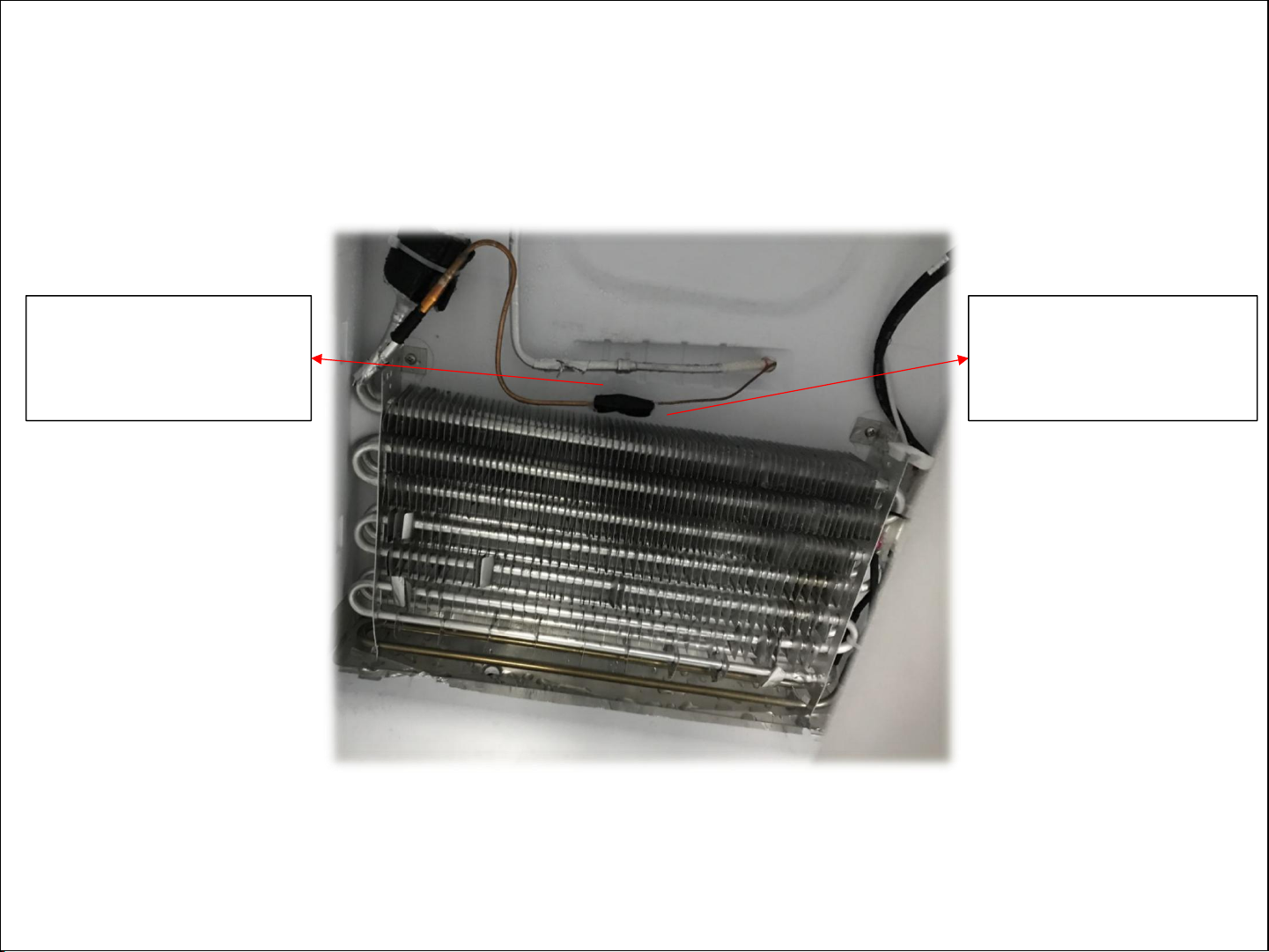
The refrigeration circulating system is as shown in the figure. TRF-436WEXPA+ is a single-system
full air-cooling frost-free refrigerator. The components of the refrigeration system are, in order,
compressor, evaporation coil, condenser, anti-condensation pipe, filter drier, capillary tube, fin
evaporator, return pipe and return transition pipe in the direction of refrigerant flow. The
schematic diagram of refrigeration is as follows:
Compressor
Filter drier
Capillary tube
Condenser
Anti-condensation pipe
Fin evaporator
Evaporation coil

Schematic diagram for compressor chamber pipe welding
Exhaust pipe and
evaporation coil inlet
(copper-steel)
Evaporation coil
outlet and anti-
condensation pipe
inlet (steel-steel)
Condenser outlet and
filter drier inlet (steel-
copper)
Filter drier outlet and capillary
tube inlet (copper-copper)
Return pipe outlet and return transition
pipe inlet (copper-copper)
Return transition pipe outlet and
suction pipe (copper-copper)
Process pipe
connection
(copper-copper)
Anti-condensation
pipe outlet and
condenser inlet
(steel-steel)

Schematic diagram for freezer compartment pipe welding
Fin evaporator outlet and
return pipe inlet
(aluminum-aluminum)
Capillary tube outlet and
fin evaporator inlet
(copper-copper)

4.Electrical system
Electrical controlling circuit diagram

5.Product operation rules


Door alarm
When the refrigerator or freezer door is not well closed or open for over 1 minute, the buzzer siren will send off
sound. Press down any key to stop alarming and the siren sounds “beep, beep, beep” again after I minute;
close refrigerator or freezer door to stop alarming.
Freezer compartment temperature reminder
When the temperature of freezer compartment is higher than -12℃, the corresponding temperature area
is lit, the digital area flashes. Press down any key to display temperature of freezer compartment when the
power is on, press again or wait for 10 seconds to restore normal display state.
Display protection function
The refrigerator will enter display protection function without any key operation for 30 seconds, and the key board is
locked automatically . Under display protection mode, press any key to exit display protection function.

6.Maintenance instructions
Before maintenance, it is necessary to get more information about the actual service
condition of the user first, and then take corresponding measures.
Service condition of the user
Guidance and handling
1. Installation
environment
No clearance around.
Surrounding clearance: Over 10cm at the back and
30cm at the top, and maintain ventilation
Unsteady installation
Install it on a flat ground and adjust the adjustable
feet.
Unsuitable installation site
Change the installation site or keep the
surrounding ventilation.
2. Service condition
Too much food stored.
The circulation of cold air in the refrigerator is
affected. Please explain the relevant contents in
the instruction manual to the user.
The stored food contains too much
water
The cold air source is blocked by stored
food
Refrigerator door is opened frequently
Try to reduce the frequency of opening the door
Unsuitable setting position of
temperature-setting dial
Set the temperature-setting dial at the
appropriate position.

Common faults of electric fittings
S/N
Fault description
Causes
Treatment
1
Freezer compartment
defrosting heater fault
Poor terminal connectors
Check each connecting terminal to ensure reliable connection
Defrosting heater fault
Use a multimeter to measure the resistance at both ends of the
heating tube, which should be about 285 Ω under normal conditions
Temperature fuse fault
Use a multimeter to measure both ends of the defrosting fuse, it
should be in conducting state
2
Unqualified grounding
resistance
The grounding wire screws of the
compressor are loose, or the
grounding wire screws of the
power cord are loose
Check the grounding of the compressor and tighten the screws;
Check the fastening of the power cord grounding screws
3
The whole machine has
no power after the power
cord is connected
The connector is loose
Check the connection of the corresponding connectors against the
physical wiring diagram
Main control board fault
Check the power input of the main control board. If the input is
normal, replace the main control board
4
Compressor does not
start
Poor terminal connection
Check the split inverter board’s signal lines, input voltage, output
voltage and the compressor connecting terminals with reference to
the physical wiring diagram, to see whether the connection is normal
Main control board fault
Detect the frequency conversion signal output end of the main
control board with an oscilloscope. If there is no output signal,
replace the main control board
Compressor fault
Under the condition that all the above are normal, remove the
triangle connector of the compressor, connect to a new compressor
and power it on. If the compressor starts normally, replace the
compressor

Faults of main electrical parts:
Electrical parts
Fault description
Troubleshooting method
Maintenance plan
The freezing fan
does not rotate
Poor compartment
refrigeration effect
1. Stick a magnet at the upper cover door switch.
After the light goes out, feel with hand whether
there is cold air blowing out from the refrigerator
air duct
2. Press the door switch of the freezer
compartment manually to feel with hand whether
there is cold air blowing out of the freezer air duct
Check the terminal connectors for
poor contact, and replace the fan
assembly
The electric damper
cannot be closed
Refrigerator
compartment is
too cold or frozen
1. Open the refrigerator air duct assembly, enter
the service program at the same time, and
manually open the electric damper to determine
whether the electric damper is normal and
controlled
Replace damper
Lighting lamps
Lamps do not light
1. Check whether the connector is connected well
2. Check whether the lamp connector on the main
control board is outputting normally
3. No lamp is lit up. Check the door switch and the
communication line
4. Some lamp beads are not lit up. Replace the
lamp board
Replacement and maintenance
Steel tube heater
It doesn't work or
defrost
1. Use multimeter to detect the resistance value of
the steel tube heater; 2. Check whether the relay
on the main control board cannot be engaged
Replacement and maintenance

1. Hold down the adjustable slide of the
turnover beam by hand;
Dismounting of turnover beam assembly
2.Rotate the turnover beam assembly; 3.Loosen the adjustable slide of the
turnover beam and remove the two screws
as shown in the figure.
4.Lift up the two hanging buttons
under the turnover beam assembly for
separation;
5.Separate the upper shaft from the door, and
then disconnect the terminal to complete the
dismounting of the turnover beam;
6.Guidelines for disassembly of some structural parts

1. Remove the three screws shown in the figure;
Dismounting of upper cap
2. Push both ends of the upper cap, and push the upper cap upwards
to separate it from the compartment to complete the dismounting;
3. Pay attention to clamping the six buckles shown in the following figure into the corresponding
position limits of the cap in the course of re-assembling;

1. Remove one screw in the frame shown in the figure;
Dismounting of toplight
2. Detach the five buckles as shown in the figure. The two rear movable buckles need to
be detached first, and then the three front fixed buckles need to be separated.

1. Remove the two screws as shown in the figure and
pull the upper edge of the air duct to separate the air
duct cover plate from the compartment;
Dismounting of the refrigerating air duct and smart damper
2. Pull out the buckles on the upper part and both sides
of the refrigerating air duct so that they are disengaged
from the compartment;
3. Remove the masking tape from the
protective area of the damper foam.
4. Open the damper foam. 5. Open the foam of the cover plate
to disassemble the top plate of
circular display board.
Table of contents
Other TCL Refrigerator manuals