Rev.
Engineering Dept,China Manufacturing Center,TCL Multimedia
NO Q'ty
A1
B2
C2
D2
Q'ty E4
2F
2G
H
NO.
1
2
3
4
38s
Prepared:Bin Tang Checked by: Approved by:
S.T Total:
PRECAUTIONS
1.The real goods used above items must be the same as BOM list's goods.
2.Operator should wear Gloves when operating.
3.The processes is operated on a strict self-test, to prevent defective products into the next process.
4.Order by serial hit the screw (take a hit one), can not appear tainted play, missed, slip teeth, etc.
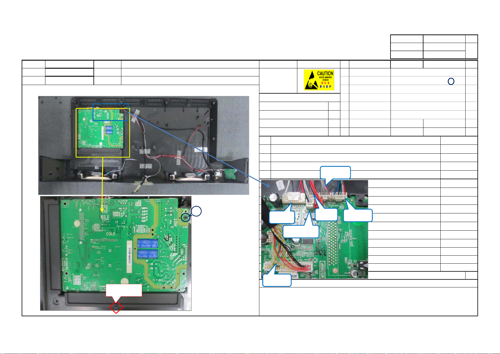
Stick the mylar on the support pin as fig.2.
4)Check the T-CON board must be completely on the lock .
Fix the vesa support(1~2)with screws on the module as fig.2. k=8±1kgf.cm
Fix the base connector (3~6)with screws on the module as fig.2. k=8±1kgf.cm
2)Examine the LOGO is right for the machine .
3)There should be no deformation of the surface shell, de-oiling, no scratching and other
undesirable phenomena.
Take out screen module on the workpalce shown in the left pictures,then check as follow:
1)To be sure that the LCD panel can not have a scratch, cracks or damage and other
adverses,then put it on sponge pad without any foreign matter.
PROCESS DESCRIPTION Oper.Parameter
Pair of Electrostatic Gloves
electronic screw driver
FIXTURES & INSTRUMENTS 62-529910-0HJ
Name 64-B40060-104G
base connector
screw for base connector
Ass'y No.
H7-KD270NZG-UR0 Section CTV ASSEMBLY 67-M52727-0G0
64-B40060-104G
Model
40D2700B MS08BP-AP
NO. 9/23
T8-40D2700B-LPM10
Customer Oper. Name Process 2 of taking the module
1.0
odified Date:
Remark Electrostatic Mark
WORK INSTRUCTION
File No.:
Part Number Description Specification
screw for vesa support
vesa support
OS-C000390.00
Issue Date:2015/11/13
module
Fig.1
1 2
Fig.2
3
4
anchorpoint
baseconnector