TCRS AC30TON Service manual

30 TON AC
OPERATING AND SERVICE MANUAL
STARTING S/N AC030-21-00001
REV -

1
TABLE OF CONTENTS
Page No.
Description
1
Table of Contents
2
Safety Information
5
Technical Data Specifications
6
Operator Control Panel
8
Operation and Service
9
Troubleshooting
10
Electrical Schematic
12
Electrical Panel Layout
13
Piping Schematic
14
Structural\Sheet Metal BOM
Contact TCRS at 440-658-2020

2
Important Safety Information
Most accidents that involve product operation, maintenance and repair are caused by failure to observe
basic safety rules or precautions. An accident can often be avoided by recognizing potentially hazardous
situations before an accident occurs. A person must be alert to potential hazards, including human factors
that can affect safety. This person should also have the necessary training, skills and tools to perform these
functions properly.
Improper operation, lubrication, maintenance or repair of this product can be dangerous and could
result in injury or death.
Do not operate or perform any lubrication, maintenance or repair on this product, until you verify
that you are authorized to perform this work, and have read and understood the operation,
lubrication, maintenance, and repair information.
Safety precautions and warnings are provided in this manual and on the product. If these hazard warnings
are not heeded, bodily injury or death could occur to you or to other persons.
The hazards are identified by the “Safety Alert Symbol” and followed by a “Signal Word” such as
“DANGER”, “WARNING” or “CAUTION”. The Safety Alert “WARNING” label is shown below.
The meaning of this safety alert symbol is as follows:
Attention! Become Alert! Your Safety is involved.
The message that appears under the warning explains the hazard and can be either written or pictorially
presented.
A non-exhaustive list of operations that may cause product damage are identified in this publication.
TCRS cannot anticipate every possible circumstance that might involve a potential hazard.
The warnings in this publication and on the product are, therefore, not all inclusive. You must not
use this product in any manner different from that considered by this manual without first satisfying
yourself that you have considered all safety rules and precautions applicable to the operation of the
product in the location of use, including site-specific rules and precautions applicable to the
worksite. If a tool, procedure, work method or operating technique that is not specifically
recommended by TCRS is used, you must satisfy yourself that it is safe for you and for others. You
should also ensure that you are authorized to perform this work, and that the product will not be
damaged or become unsafe by the operation, lubrication, maintenance or repair procedures that
you intend to use.
The information, specifications, and illustrations in this publication are on the basis of information that was
available at the time that the publication was written. The specifications, torques, pressures,
measurements, adjustments, illustrations, and other items can change at any time. These changes can
affect the service that is given to the product. Obtain the complete and most current information before you
start any job.
When replacement parts are required for this
product, TCRS recommends using parts with
equivalent specifications including, but not limited
to, physical dimensions, type, strength and material.
Failure to heed this warning can lead to premature
failures, product damage, personal injury or death.
Contact TCRS at 440-658-2020

3
Universal Warning
Do not operate or work on this equipment unless
you have read and understand the instructions
and warnings in the Operation and Maintenance
Manuals. Failure to follow the instructions or heed
the warnings could result in serious injury or
death.
Electrical Shock
The safety message for electrical shock is located on the control panel.
WARNING! Shock/Electrocution Hazard! Read
and understand the instructions and warnings in
the Operation and Maintenance Manual. Failure to
follow the instructions or heed the warnings
could cause serious injury or death.
Additional Messages
There are several warning labels on this unit. Please be aware of all warning labels.
Make sure that all of the messages are legible. Clean the messages or replace the messages if the words or images are
unreadable. When you clean the messages, use a cloth, water and soap. Do not use solvent, gasoline, or other harsh
chemicals to clean the messages. Solvents, gasoline, or harsh chemicals could loosen the adhesive that secures the
messages. Loose adhesive will allow the messages to fall off.
Replace any message that is damaged, or missing. If a message is attached to a part that is replaced, install a message on
the replacement part.
General Hazard Information Attach a “Do Not Operate” warning tag to the start switch or controls before the
unit is serviced or repaired. Attach the warning tags to the unit and to the operator
control station. When appropriate, disconnect the starting controls. Do not allow
unauthorized personnel on the unit, or around the unit when the unit is being
serviced. Cautiously remove the following parts. To help prevent spraying or
splashing of pressurized fluids, hold a rag over the part that is being removed.
•Gage ports
•Breathers
•Drain plugs
Use caution when cover plates are removed. Gradually loosen, but do not remove
the last two bolts or nuts that are located at opposite ends of the cover plate or the
device. Before removing the last two bolts or nuts, pry the cover loose in order to
relieve any spring pressure or other pressure.
Wear a hard hat, protective glasses, and other protective equipment, as required.
Do not wear loose clothing or jewelry that can snag on parts of the unit.
Ensure that all protective guards and all covers are secured in place on the unit.
Never put maintenance fluids into glass containers. Glass containers can break.
Use all cleaning solutions with care.
Report all necessary repairs.
Contact TCRS at 440-658-2020

4
Unless other instructions are provided, perform maintenance under the following conditions:
The unit is powered down and cannot be started.
The protective locks on the controls are in the locked out position.
Do not attempt any repairs that are not understood. Use the proper tools.
Replace any equipment that is damaged or repair the equipment.
Pressurized Air and Water
Pressurized air and/or water can cause debris and/or hot water to be blown out which could result in personal injury.
The maximum air pressure for cleaning purposes must be reduced to 205 kPa (30 psi) when the air nozzle is deadheaded and
used with effective chip guarding (if applicable) and personal protective equipment. The maximum water pressure for cleaning
purposes must be below 275 kPa (40 psi). When pressurized air and/or pressurized water is used for cleaning, wear protective
clothing, protective shoes, and eye protection. Eye protection includes goggles or a protective face shield. Always wear eye
protection for cleaning the cooling system. Avoid direct spraying of water on electrical connectors, connections, and
components. When using air for cleaning, allow the machine to cool to reduce the possibility of fine debris igniting when
redeposited on hot surfaces.
Fluid Penetration
Always use a board or cardboard when you check for a leak. Leaking fluid that is under pressure can penetrate body
tissue. Fluid penetration can cause serious injury and possible death. A pinhole leak can cause severe injury.
If fluid is injected into your skin, you must get treatment immediately. Seek treatment from a doctor that is familiar with this
type of injury.
Containing Fluid Spillage
Care must be taken to ensure that fluids are contained during performance of inspection, maintenance, testing,
adjusting, and repair of the product. Be prepared to collect the fluid with suitable containers before opening any
compartment or disassembling any component containing fluids. Dispose of all fluids according to local regulations and
mandates.
Dispose of Waste Properly
Improperly disposing of waste can threaten the environment. Potentially harmful fluids should be disposed of according to local
regulations. Always use leak proof containers when you drain fluids. Do not pour waste onto the ground, down a drain, or into
any source of water.
Burn Prevention
Do not service an operating unit. Allow the compressor to cool before any maintenance is performed.
Contact TCRS at 440-658-2020

5
Technical Data Specifications
Model Number
AC30TON
Serial Number
AC030-21-00001
Capacity
360,000 BTUH
Voltage
480V 3PH 60Hz
FL Amps - Cooling
82 AMPS
Interrupt Rating
10KAIC
Minimum Circuit
Ampacity
125 AMPS
Enclosure Type
Type 3R
Control
110V
Control
24V DC
Compressor
H.P.
20 HP x 2
FLA
32 AMPS x 2
X 2
Circuit Protection
32 AMPS each
Condenser Fan Motor
WATTS
2700 WATTS x 2
FLA
4 AMPS x 2
Circuit Protection
10 AMPS each
Blower Motor
WATTS
3100 WATTS x 2
FLA
5 AMPS x 2
Circuit Protection
10 AMPS each
Condensate Pump
H.P.
1/150 HP
FLA
1 AMP
Circuit Protection
2 AMPS
Control Transformer
Rating
500 VA
Primary Fuse
ATQR4
Secondary Fuse
ATQR4
Refrigerant
R-410A
Charge system 1 & 2
12 LBS. x 2
High Press Cut Out
610 PSIG
Low Press Cut Out
40 PSIG
Oil
Bitzer BVC32 180oz.
DBA @20’
73 DBA
Weight
2250 LBS.
Made in USA
Contact TCRS at 440-658-2020

Operator Control Panel
Main Disconnect Switch – Turns main power on to the entire system and is protected by the
main circuit breaker.
HMI MAIN screen - Control system functions.
POWER ON\OFF touch button – Enable System Power and control.
BLOWER SET touch setting – Set blower speed from 50% to 100%
TEMP SET touch setting- Set desired temperature setpoint.
RETURN, SUPPLY, REMOTE touch button -- Select which sensor will be monitored.
BLOWER touch button – Start blower.
SYS 1&2 COMP ON\OFF touch button -- Start\stop system 1&2 compressor.
FAULT touch button –RED when fault is active, press to display Fault screen.
Config touch button – Password protected to set initial system settings.
Monitor touch button – Press to display Monitor screen.
FAULT Sc reen
Fault indication lights turn red when fault is active and stop system operation.
PHASE MONITOR - Main power phasing and phase loss status.
BLOWER 1&2 - Blower motor 1&2 status.
CONDENS FAN 1&2 – Condenser motor 1&2 status.
HIGH PRESS CO TRIP – System pressure above High Pressure Cut Out.
MOTOR OVERLOAD – Compressor system 1&2 status.
HIGH PRESSURE SW – System pressure 1&2 above limit, tripped mechanical switch.
LOW PRESSURE SW – System pressure 1&2 below limit, tripped mechanical switch.
Contact TCRS at 440-658-2020
6

7
Configuration Settings Screen –Password protected to set initial system settings
Head Press Setpoint –Target pressure that condenser fan will adjust to maintain
High Press Cutout –Pressure that system should not run above and will shut down
Temp Offset –Temperature offset above setpoint when system will start
Select Temp Display –Selects temperature display units (Celsius or Fahrenheit)
COND AUTO –Switches condenser fan to manual mode for testing. Set 0-100
Monitor Screen –Monitor the Suction (Low) Pressure and Discharge (High) Pressure.
For System 1&2
Contact TCRS at 440-658-2020

8
Operation and Service
Designed Performance Features
Air conditioning system design requirements:
1.
To be located outside of the conditioned space by the use of 2 -20 inch flexible supply air ducts and
2 -20 inch flexible return air ducts.
2.
To operate in outdoor temperatures from 0° F to 100° F.
3.
To operate from local utility power, generated power, or transformer power.
4.
To operate immediately, no warm up time required.
Refrigerant Circuit System 1&2 Components
1.
A fully hermetic scroll compressor with over temperature protection. The scroll compressor is unique
in its ability to start in a flooded liquid state and run with liquid feedback for short periods of time,
although it is not recommended to operate under these conditions continually because of lubrication
concerns.
2.
Vibration absorbers in the compressor suction and discharge lines to minimize working stress on
the refrigerant plumbing.
3.
A condenser cooled by an electronically commutated (EC) fan.
4.
A liquid line filter/dryer to absorb moisture and contaminants.
5.
A liquid line sight glass for monitoring the refrigerant charge and moisture content.
6.
An external equalized thermal expansion valve to properly adjust the refrigerant flow rate to the
evaporator coil for the current heat load conditions.
7.
An evaporator coil to absorb heat from the conditioned air.
8.
A hot gas bypass valve for capacity control and to maintain a set suction pressure of 50-52 psig.
This valve is plumbed from the discharge line to the inlet of the evaporator coil, allowing hot
refrigerant gas to mix with the cool refrigerant liquid and not to overheat the compressor.
9.
High and low pressure switches, used as a safety, to shut down the compressor if discharge
pressure rises above the cutout limit setting or if the suction pressure drops below the cutout limit.
All of the refrigerant circuit components are standard "off the shelf' and are easily recognized by a certified
refrigeration technician.
For operation and service concerns please call:
440-658-2020
Troubleshooting
Caution must be taken when troubleshooting the electrical circuit and should only be performed by a trained service
technician.
Generally, troubleshooting will begin by viewing the Fault screen on the Operator Control Panel.
INDICATION
POSSIBLE
CAUSE
CORRECTIVE
ACTION
Nothing
operates
Main power
Control power
Check voltage and phasing
Check transformer and fusing
Phase Monitor
Fault
Incorrect phasing
Poor Voltage
Switch two of the main power cables
Check for correct supply voltage
Blower Fault
Breaker tripped
Motor failure
Find cause, reset breaker
Verify 480V 3ph is present and 0-10VDC control
voltage is present, replace blower motor
Condenser Fan
Fault
Breaker tripped
Motor failure
Find cause, reset breaker
Verify 480V 3ph is present and 0-10VDC control
voltage is present, replace condenser motor
High Pressure
Cutout Fault
High pressure trip
Check condenser fan operation
Check for restricted condenser air flow
Check for refrigerant over charge
Press High Pressure Fault to reset.
Motor Overload
Fault
Compressor overheated
Allow compressor to cool down
High Pressure
SW Fault
Mechanical High
Pressure switch tripped
Allow High Pressure to drop below 500PSIG
Reset mechanical High Pressure switch
Low Pressure
SW Fault
Mechanical Low
Pressure switch tripped
Check for refrigerant charge
Fault will correct when pressure is above 70PSIG
Only blower
operates
Thermostat
No call for cooling
Verify correct control temp is selected
Verify Setpoint is below current control temp
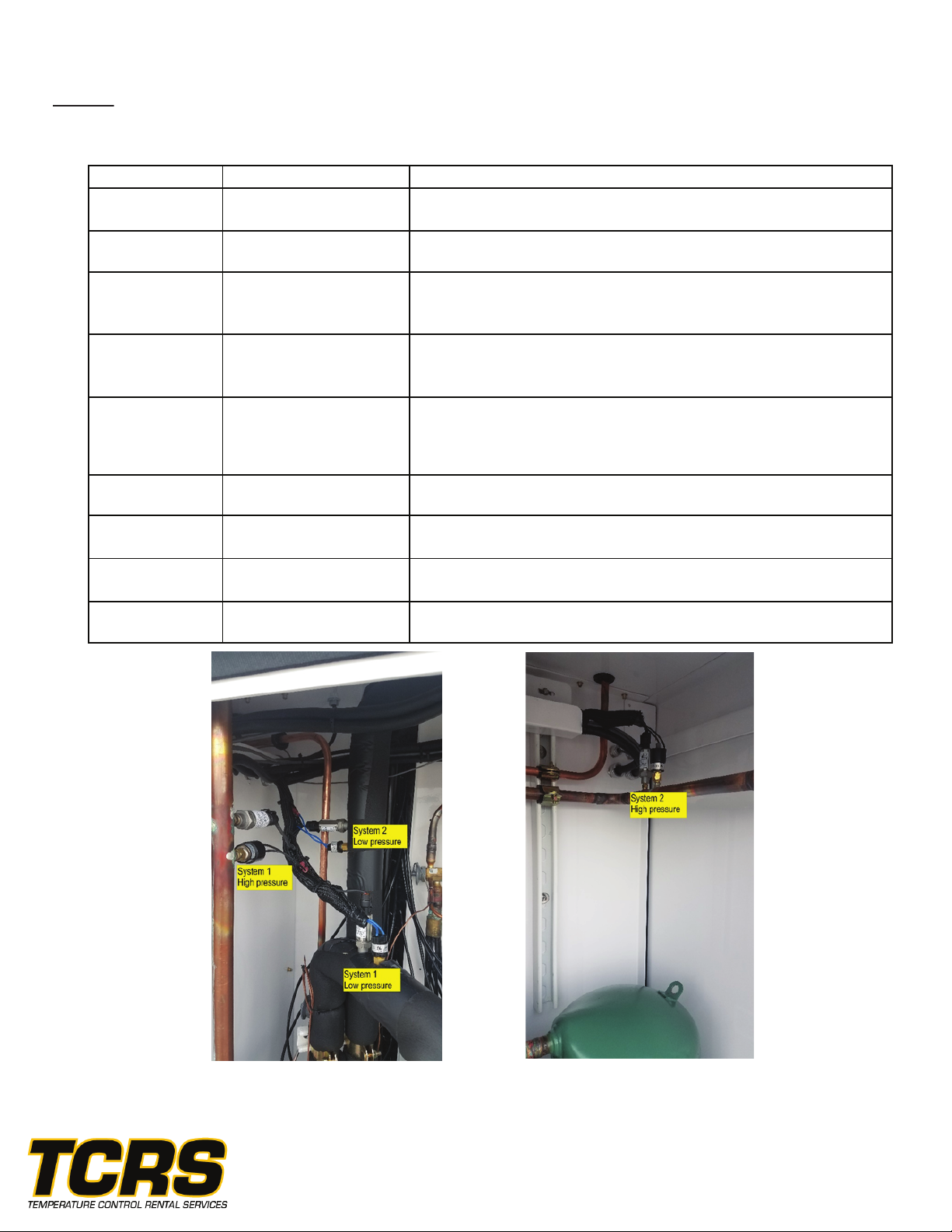
High Pressure and low pressure switches are located in the compressor compartment.
The high pressure switch must be physically reset if pressure exceeds 600psi.
The low pressure switch will reset automatically when pressure is above 80psi.
Contact TCRS at 440-658-2020
9

10
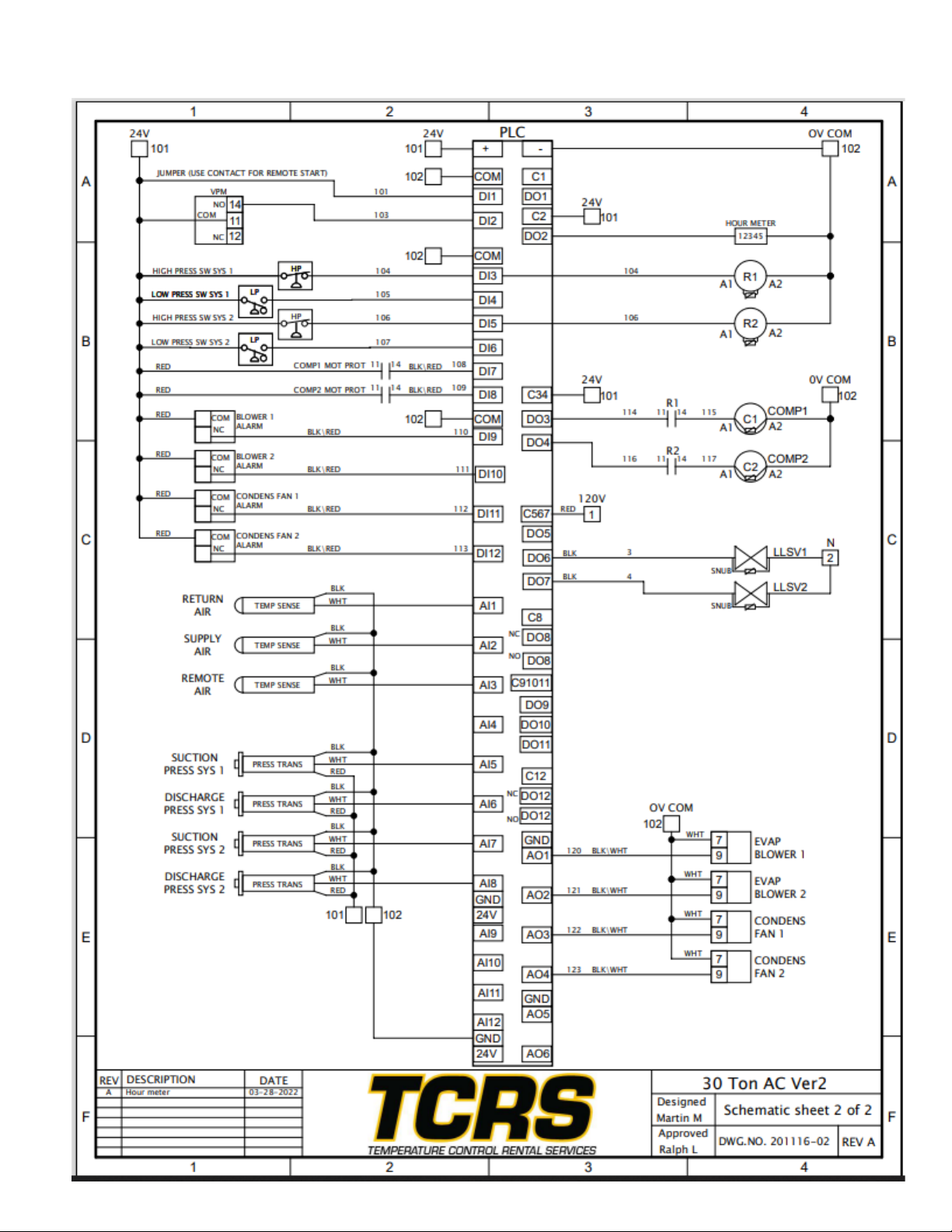
Electrical Schematic
Contact TCRS at 440-658-2020
11
Contact TCRS at 440-658-2020
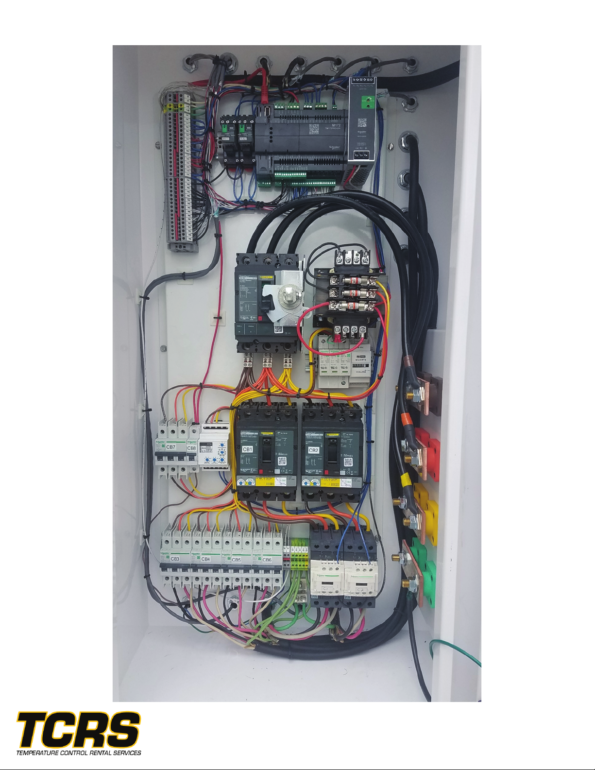
Electrical Panel Layout
12 Contact TCRS at 440-658-2020

13
Piping Schematic
Contact TCRS at 440-658-2020

Contact TCRS at 440-658-2020
Structural\Sheet Metal BOM
14

Contact TCRS at 440-658-2020
15
Table of contents
Other TCRS Industrial Equipment manuals


