TCS FBI4500-0100 User manual

TCS TürControlSysteme AG, TCS Hotline: +49 ( )0 41 94 / 98 81 188 Subject to technical changes.
Product information
PTZ camera interface
FBI4500-0100

2 11/2012
TCS TürControlSysteme AG TCS Hotline: +49 (0) 41 94 / 98 81 188 Subject to technical changes.
FAX: +49 (0) 41 94 / 98 81 29 Mail: hotline@tcsag.de PI_FBI4500-0100.doc 2A
Table of contents
Scope of delivery .................................................................................................................3
Safety instructions................................................................................................................3
General safety regulations ...............................................................................................3
Installation –protective measures....................................................................................3
Terms...................................................................................................................................4
Intended use........................................................................................................................4
Short description..................................................................................................................5
Functional description ......................................................................................................5
Functions at the TCS:BUS®.............................................................................................5
Indication and operating elements................................................................................5
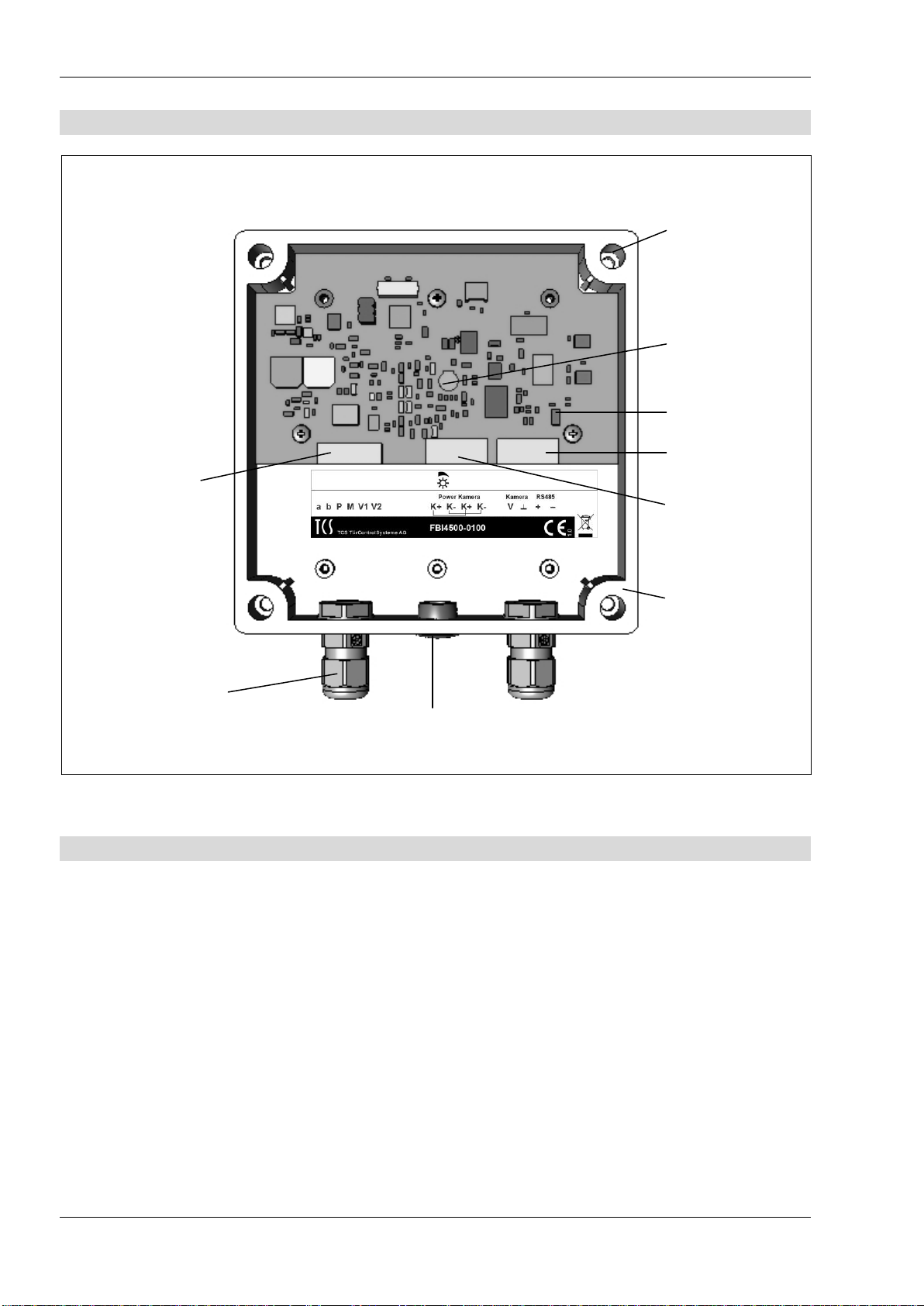
Device overview...................................................................................................................6
Technical data .....................................................................................................................6
Installation............................................................................................................................7
Installation location...........................................................................................................7
Open and close the housing.............................................................................................7
Connect the lines.................................................................................................................7
Connection lines...............................................................................................................7
5-wire special operation ...................................................................................................8
Connect the camera.........................................................................................................8
Voltage supply connection............................................................................................8
Note for the connection of more than one interface......................................................8
Setup the PTZ camera interface as end device............................................................8
Wiring diagram TCS:BUS®system...................................................................................9
Connection diagram.........................................................................................................9
Commissioning ..................................................................................................................10
Commissioning the system ............................................................................................10
Storage in case of a voltage breakdown ........................................................................10
Configuration .....................................................................................................................10
Presettings ex works......................................................................................................10
Configuration options.........................................................................................................10
Preposition of a camera .................................................................................................11
Setup preposition........................................................................................................11
Delete prepositions.....................................................................................................11
Operation....................................................................................................................11
General information on the conduit in TCS video systems ................................................12
6-wire operation..............................................................................................................12
Principle loop resistance.............................................................................................13
Measurement loop resistance.....................................................................................13
Cleaning.............................................................................................................................14
Conformity .........................................................................................................................14
Information on disposal......................................................................................................14
Warranty............................................................................................................................14
Notizes...............................................................................................................................15
Service...............................................................................................................................16

11/2012 3
TCS TürControlSysteme AG TCS Hotline: +49 (0) 41 94 / 98 81 188 Subject to technical changes.
FAX: +49 (0) 41 94 / 98 81 29 Mail: hotline@tcsag.de PI_FBI4500-0100.doc 2A
Scope of delivery
1 x FBI4500-0100
Product information
Safety instructions
General safety regulations
!
Attention! Mounting, installation, commissioning and repair of electronic devices have
to be carried out only by qualified electricians. The latest accident prevention regulati-
ons must be observed.
For working on systems with main connection of 230 V alternating voltage, the safety re-
quirements according to DIN VDE 0100 must be observed.
When installing TCS:BUS®systems, the general safety regulations for telecommunication
systems according to VDE 0800 must be observed. Inter alia:
separated conduit of heavy current and low current lines,
minimum distance of 10 cm in case of a common conduit,
use of separators between heavy and low current lines within shared cable ducts,
use of standard communication lines, e.g. J-Y (St) Y with a diamter of 0.8 mm,
exisiting lines (modernisation) with deviating cross-sections can be used in compliance
with the loop resistance.
Installation –protective measures
!
With suitable measures to protect against lightning, it has to be ensured that a voltage
of 32 V DC is not exceeded at the connections a, b, E, P, M, V1, V2, V, ┴, +, −.

4 11/2012
TCS TürControlSysteme AG TCS Hotline: +49 (0) 41 94 / 98 81 188 Subject to technical changes.
FAX: +49 (0) 41 94 / 98 81 29 Mail: hotline@tcsag.de PI_FBI4500-0100.doc 2A
Terms
6-wire operation
Standard operation mode for TCS video systems, where two separated ground
wires (b and M) are used.
5-wire special
operation
If there are only 5 wires available for the device, so that the M-wire cannot be
connected, a 5-wire special operation is possible.
PTZ camera
If a PTZ camera (Pan Tilt Zoom) has been installed, the image section shown
on the display can be changed by panning horizontally,
tilting vertically as well as by zooming in and out.
preferred position
Preferred camera setting. The position is stored in the camera and can be
configured in the PTZ camera interface via the configuration software con-
figo™ (as of version 1.7.x).
By specific actions at the TCS:BUS®(door call, control function) the positions
can be controlled.
On-Screen-Display
(OSD)
Dropdown menu which is displayed on the screen and can be activated by
pressing the menu or image button of the device.
Intended use
The PTZ camera interface FBI4500-0100 is a device to connect PTZ cameras of other
manufacterers to the TCS:BUS®video system.
The device is suited for surface-mount.
!
Using the PTZ camera interfaces is only useful in combination with a camera, which
can be controlled by the PTZ control commands.
To control the camera, a video indoor station with control keys (resp. navigation but-
tons) LEFT, RIGHT, UP, DOWN is necessary (e.g. series IMMx3x0, ecoos™
IVW22xx, sky™IVW2221 or skyline™IVW3012).
Max. 16 devices and 16 cameras are permitted when using up to 5 video switches
at one TCS:BUS®.

11/2012 5
TCS TürControlSysteme AG TCS Hotline: +49 (0) 41 94 / 98 81 188 Subject to technical changes.
FAX: +49 (0) 41 94 / 98 81 29 Mail: hotline@tcsag.de PI_FBI4500-0100.doc 2A
Short description
Functional description
The PTZ camera interface, connected to a PTZ camera, can be operated as stand-
alone camera or allocated to a (video) front-door station at the TCS:BUS®.
The device provides the video image of the connected PTZ camera via two-wire video
signal.
The interface controls the PTZ camera via a standard RS485 connection. Supported
types of protocol: Pelco D, Pelco P and Samsung.
Functions at the TCS:BUS®
By navigating with the control keys (resp. Navigation buttons) LEFT, RIGHT, UP,
DOWN at the indoor station, a specific section of the image can be selected via a
PTZ camera.
With the protocol “topstitch“ or with the “control function“ preferred positions can be
controlled.
The configuration software configoTM supports the devices as of version 1.7.x.
Indication and operating elements
Potentiometer
A two-wire video sender converts the asymmetric camera
signal into symmetric signal, which can be used in the
TCS video system. This can be displayed on all video
indoor stations. With the potentiometer, the video level is
manually adjustable:
Turning right: increase the output level
Turning left: reduce the output level

6 11/2012
TCS TürControlSysteme AG TCS Hotline: +49 (0) 41 94 / 98 81 188 Subject to technical changes.
FAX: +49 (0) 41 94 / 98 81 29 Mail: hotline@tcsag.de PI_FBI4500-0100.doc 2A
Device overview
Device without cover
Technical data
Input voltage (P-wire): +26 V DC (power supply and control unit)
Housing: plastics, transparent cover
Dimensions (in mm): H 130 x W 130 x D 35
Weight 305 g
Degree of protection: IP65
Acceptable ambient temperature: −20 °C to +50 °C
Input current: I(a) = 0.4 mA
Input current: I(P) = 25 mA (stand-by)
Max. input current: I(Pmax) = 40 mA
Video signal input: 75 Ohm, asymmetric 1 Vss FBAS
Output level (2-wire video signal): −3 dB to +9 dB (manually adjustable)
6-wire technique necessary!
Connection
terminal
TCS:BUS®
Jumper
4 x Cover
screws
IP65
Housing with
transparent co-
ver
Potentiometer
video level
Connection
terminal
loop-through
Connection ter-
minal camera
2 x Cable gland
(M12 screws)
Dummy plugs

11/2012 7
TCS TürControlSysteme AG TCS Hotline: +49 (0) 41 94 / 98 81 188 Subject to technical changes.
FAX: +49 (0) 41 94 / 98 81 29 Mail: hotline@tcsag.de PI_FBI4500-0100.doc 2A
Installation
Installation location
The PTZ camera interface is suitable for the inner and outer installation
(housing IP65).
!
When installing the device outdoors, please observe that the cable gland (M12
screw connection) must be facing downwards!
Please observe the documentation of the camera manufacturer !
Open and close the housing
Loosen the cover screws of the PTZ camera interface. Remove the cover.
Use the lower cover to mark out the four attachment holes at the corners of the housing.
!
Do not use the lower cover as drilling template as it may cause damage to the de-
vice!
Drill the marked holes and insert dowels into the wall if necessary. Screw the housing
firmly to the wall.
Guide the connection lines through the cable gland (M12 screws).
Close the housing only after the installation and configuration.
Connect the lines
Connection lines
The connection of the connection line is attained by a M12 screw connection.
Use only one cable with jacket, diameter 3.5 to 7 mm per screw connection.
Cross-sections for connection lines
Connection TCS:BUS
Permitted cross-section (diameter)
Max. number of wires per terminal contact
Connections camera
Permitted cross-section (diameter)
Max. number of wires per terminal contact
0.32… 2.1 mm2(Ø 0.3 … 1.6 mm)
each 2 x Ø 0.8 mm or 3 x Ø 0.6 mm
0.08… 1.3 mm2(Ø 0.32 … 1.3 mm)
each 2 x Ø 0.8 mm or 3 x Ø 0.6 mm

8 11/2012
TCS TürControlSysteme AG TCS Hotline: +49 (0) 41 94 / 98 81 188 Subject to technical changes.
FAX: +49 (0) 41 94 / 98 81 29 Mail: hotline@tcsag.de PI_FBI4500-0100.doc 2A
5-wire special operation
5-wire special operation only with
jumper from the b- to the M-wire in
case of max. 3 devices per door
communication system are permitted.
!
The installation of a jumper between the b- and the M-wire is only permitted when ob-
serving several conditions. Regarding a solution for your special project, please con-
tact our technical hotline.
Connect the camera
Please observe the documentation of the manufacturer!
Voltage supply connection
!
The voltage supply of the PTZ camera is not realised via the PTZ camera interface
and not via the TCS:BUS®.
The PTZ camera is to supply separately with a power supply unit which is suitable
for the camera.
To connect the special voltage supply, the terminals K Power Kamera can be used
in the FBI4500.
ATTENTION: The terminals K Power Kamera must not exceed 2 A / 26 V!
Note for the connection of more than one interface
!
Max. 16 interfaces and 16 cameras are permitted when using up to 5 video switches at
one TCS:BUS®.
Setup the PTZ camera interface as end device
If the device is installed at the end of a TCS:BUS® video strand, set the matching resis-
tor!

11/2012 9
TCS TürControlSysteme AG TCS Hotline: +49 (0) 41 94 / 98 81 188 Subject to technical changes.
FAX: +49 (0) 41 94 / 98 81 29 Mail: hotline@tcsag.de PI_FBI4500-0100.doc 2A
Wiring diagram TCS:BUS®system
Connection diagram
Place matching
resistor at the
last video
indoor station!
Floor
push
button
Floor
push
button

10 11/2012
TCS TürControlSysteme AG TCS Hotline: +49 (0) 41 94 / 98 81 188 Subject to technical changes.
FAX: +49 (0) 41 94 / 98 81 29 Mail: hotline@tcsag.de PI_FBI4500-0100.doc 2A
Commissioning
Commissioning the system
Install the devices of the system voltage-free and completely.
The PTZ camera interface is to be connected to the TCS:BUS®according to the con-
nection diagram.
Check the a-, b- and P-wire against each other for short-circuits.
Connect the PTZ camera according to the connection diagram.
Switch ON the mains voltage.
The PTZ camera interface is ready for operation.
Storage in case of a voltage breakdown
The data, stored on the EEPROM storage which is integrated into the micro controller is
still available even after a voltage breakdown.
Configuration
Presettings ex works
The device is equipped with an EEPROM which stores the following device settings ex
works:
AS-address camera 1
0
Control function for moving to prepositions
239
Second AS-address for moving to preposition 2 camera 2
deactivated
Automatic Stop protocol
deactivated
Camera address
1
Type of PTZ protocol to control the camera
Pelco D
Baud rate
2400 Bd
Configuration options
Function
Manual
configoTM
version 1.7.x
Video level
x
-
Allocate camera AS-address for moving to preposition 1
-
x
Train / delete preposition of the connected camera
-
x
Allocate control function numbers to each preposition
-
x
Allocate 2nd AS-address for moving to preposition 2
-
x
Allocate control function number for topstitching between the preposi-
tions
-
x
Determine PTZ protocol type (match with the camera type)
-
x
Activate / deactivate the sending of the automatic stop protocol, when
activating: set delay
-
x
OSD camera menu
-
x

11/2012 11
TCS TürControlSysteme AG TCS Hotline: +49 (0) 41 94 / 98 81 188 Subject to technical changes.
FAX: +49 (0) 41 94 / 98 81 29 Mail: hotline@tcsag.de PI_FBI4500-0100.doc 2A
Preposition of a camera
The following settings can be realised with the configuration software configoTM as of ver-
sion 1.7.x.
Setup preposition
Start the configuration software configo™ and create an FBI4500 in your project. Open
the device in configo™.
Activate the image of an indoor station to set up the required image section.
With the control keys (resp. navigation buttons) of this indoor station you can move the
PTZ camera into the required direction (and the required zoom, as far as possible),
or: move the camera directly via configo™.
To store the preposition in the PTZ camera, press the button “Store preset x“.
Delete prepositions
Start the configuration software configo™.
Open the device FBI4500 within the configo™.
To delete the preposition in the PTZ camera, press the button “Delete preset x“.
Operation
With the control keys (resp. navigation buttons) LEFT, RIGHT, UP, DOWN at the video
indoor station you can move to the stored pre-position .
Note:
If a video image was activated and a pre-position selected, the visible image section remains the
same if, at the same time, a door call comes in and the call is accepted.

12 11/2012
TCS TürControlSysteme AG TCS Hotline: +49 (0) 41 94 / 98 81 188 Subject to technical changes.
FAX: +49 (0) 41 94 / 98 81 29 Mail: hotline@tcsag.de PI_FBI4500-0100.doc 2A
General information on the conduit in TCS video systems
6-wire operation
The 6-wire operation is the standard operation mode. It is video operation with two sepa-
rated ground lines (b and M).
The cable routing is determined by the structural conditions and is only limited by the
length.
Observe when selecting the cable length: the loop resistance a-b and M-P must not ex-
ceed a maximum of 8 Ω (table 1).
If the loop resistance exceeds 8 Ω: use multiple wiring of the strands (double drilled
lines).
Optional strand or star shaped wiring.
Do not use more than 20 video indoor stations per strand. For systems with more video
indoor stations, use video distributors (FVY1200, FVY1400).
Up to 64 front-door stations (16 of them video front-door stations) and an unlimited
number of indoor stations can be connected polarity-free (a/b) within a system (polarity-
free only in 6-wire operation). Thus, a suitable power supply and control unit must be
used.
Table 1: Loop resistances
Length of the lines a-b/ M-P
in m
0BLine diameter
0.6 mm
0.8 mm
Loop resistance in Ω
10
1.28
0.71
20
2.55
1.43
30
3.83
2.14
40
5.10
2.86
50
6.38
3.57
60
7.65
4.29
70
5.00
80
5.71
90
6.43
100
7.14

11/2012 13
TCS TürControlSysteme AG TCS Hotline: +49 (0) 41 94 / 98 81 188 Subject to technical changes.
FAX: +49 (0) 41 94 / 98 81 29 Mail: hotline@tcsag.de PI_FBI4500-0100.doc 2A
Principle loop resistance
Measurement loop resistance
None of the devices (AS, IS or FE) should be fur-
ther than 20 Ohm away from the power supply and
control unit (VS).
Rule:
Switch off the 230 V / 50 Hz of the VS.
Install a-b short-circuit at the VS.
All other devices do not disturb the measurement
and can stay connected.
Measure the loop resistance at the strand at a/b
of the last IS or AS.
8 Ohm:
max. 65 m distance AS-VS on 0.6 mm diameter
max. 115 m distance AS-VS on 0.8 mm diameter
AS Front-door station
VS Power supply and control unit
IS Indoor station
FE Extended function
short-circuit
a,b here

14 11/2012
TCS TürControlSysteme AG TCS Hotline: +49 (0) 41 94 / 98 81 188 Subject to technical changes.
FAX: +49 (0) 41 94 / 98 81 29 Mail: hotline@tcsag.de PI_FBI4500-0100.doc 2A
Cleaning
!
Avoid water from entering the device!
Do not use any abrasive detergents!
Clean the device with a dry or slightly wet cloth.
Remove stronger stains with a mild household cleaner.
Conformity
The declarations of conformity are available under www.tcsag.de, Downloads, trade
information.
Information on disposal
The adjoining symbol shows, that the device has to be disposed separately from
domestic waste. The materials used are recyclable. Please do help protecting our
environment and dispose the device via a collection point for electronic scrap.
Dispose the parts of the packaging in collecting tanks for cardboard and paper
resp. plastics.
Warranty
We offer a simplified processing in case of warranty for electricians.
Please note our conditions of sale and delivery, download from www.tcsag.de,
Downloads, trade information.
Please contact the TCS HOTLINE.

11/2012 15
TCS TürControlSysteme AG TCS Hotline: +49 (0) 41 94 / 98 81 188 Subject to technical changes.
FAX: +49 (0) 41 94 / 98 81 29 Mail: hotline@tcsag.de PI_FBI4500-0100.doc 2A
Notes

16 11/2012
TCS TürControlSysteme AG TCS Hotline: +49 (0) 41 94 / 98 81 188 Subject to technical changes.
FAX: +49 (0) 41 94 / 98 81 29 Mail: hotline@tcsag.de PI_FBI4500-0100.doc 2A
Service
Please send your questions and inquiries to
TCS HOTLINE 0 41 94 / 98 81 188
Head quarters
TCS TürControlSysteme AG, Geschwister-Scholl-Str. 7, D-39307 Genthin
Phone.: +49 (0) 39 33 / 87 99 10, FAX: +49 (0) 39 33 / 87 99 11, www.tcsag.de
Table of contents
Other TCS Recording Equipment manuals