TCW Technologies IBBS-12v-3ah-CRT-V User manual

p/n 725.0002 REV 3.0 © 2023 TCW Technologies, LLC.
1
Integrated Back-up Battery System
Model: IBBS-12v-3ah-CRT-V
The Integrated Back-up Battery System, IBBS,is an electronic
system that combines a Lithium-Iron-Phosphate (Li-Fe-PO4) battery
pack, a charger and switching logic in one convenient package. The
IBBS provides an engineered solution to enable an endurance bus for
critical loads found in aircraft. It simplifies the wiring and installation of
a source of back-up power by integrating all of the key elements in a
single enclosure. The IBBS system provides back-up power to critical
electronic loads such as EFIS, GPS, Autopilots, Radios, Electronic
Ignition systems and engine monitor systems.
Integral to the IBBS is a lithium-iron-phosphate battery pack and a
matched charging system to ensure the battery is properly charged
and maintained. The system also includes switching circuitry to
provide a stable source of output power during normal and emergency
operations. The IBBS system also provides signals to other equipment
such as EFIS systems to communicate the operating state of the main
aircraft bus as well as the state of the battery.

p/n 725.0002 REV 3.0 © 2023 TCW Technologies, LLC.
2
The IBBS system connects to the standard aircraft power bus and
provides outputs to critical equipment that require back-up power.
Additionally, the IBBS system provides surge and sag protection for
connected equipment, allowing operation of critical equipment during
engine starting.
The IBBS system is suitable for use with equipment such as Garmin
and Avidyne navigators, G3X series of avionics, Grand Rapids
Technologies EFIS systems, Advanced Flight Systems EFIS, Dynon
EFIS, Aspen Avionics and MGL EFIS, TruTrak Autopilots and EFIS,
Trio Autopilots, JPI and EI engine monitors, SureFly electronic
ignitions, Lycoming EIS electronic ignitions, and ElectroAir electronic
ignitions.
IBBS must be installed using the current aircraft standards and practices as
shown in AC 43.13-2A/1B.
IBBS products are covered by US Patent 8,189,305
Table of Contents
Limitations pg. 3
Installation Information: pg. 3-6
General Product information: pg. 6-7
Battery Capacity details: pg. 8
Normal Product Operation: pg. 9
Emergency Operation: pg. 9
Instructions for Continued Airworthiness: pg. 10-12
Specifications pg. 13
Functional performance, environmental testing pg. 14
Environmental Qualification Statement pg. 15
Connector Pin-out pg. 16
Mounting plate drawing pg. 17
General Wiring diagram pg. 18
Example Wiring diagrams pg. 19-20
Support and Warranty information pg. 21

p/n 725.0002 REV 3.0 © 2023 TCW Technologies, LLC.
3
Limitations:
This article meets the minimum requirements of technical standard order (TSO) C179b.
Installation of this article requires separate approval.
The conditions and tests for TSO approval of this article are minimum performance
standards. It is the responsibility of those installing this article either on or within a specific
type or class of aircraft to determine that the aircraft installation conditions are within the
TSO standards which include any accepted integrated non-TSO function standards. TSO
articles and any accepted integrated non-TSO functions(s) must have separate approval
for installation in an aircraft. The article may be installed only according to 14 CFR Part 43
or the applicable airworthiness requirements.
This article may not be installed as the sole source of power for an instrument or avionic
device that has no other redundancy in the aircraft. (i.e., If an aircraft has one and only one vhf
radio it must have an additional source of power beside the IBBS system to qualify for installation.)
See page 13 for Performance Specifications and potential limitations and ratings under
various conditions, including environmental and application installations. See Item 3
below for installation location limitations.
Installation Information:
1. IMPORTANT NOTE:
Consult the attached wiring diagrams to identify wiring connections appropriate to
the particular installation. Please note, some equipment such as GPS’s and EFIS
systems may be provided with multiple power inputs. These inputs are often
identified as “Aircraft Power 2”.For these installations the output of the IBBS must
be connected to the “back-up” power input of the respective device. For equipment
having only a single power input terminal the IBBS pass-thru power function must be
utilized. (This is typical of devices such as communication radios, transponders,
autopilots, fuel pumps, and electronic ignitions). The IBBS system may be fed from
a bus that remains active during engine starting, such as the master bus or it may be
fed from an avionics bus that is switched off during engine starting.
2. Check that the total connected load (summed value of all four output wires of the
IBBS) is less than the following product ratings:
IBBS-12v-3ah-CRT-V
5 amps maximum continuous current
10 amps peak for radio transmissions and transient loads*
*(30 seconds max duration)

p/n 725.0002 REV 3.0 © 2023 TCW Technologies, LLC.
4
3. Mount the IBBS system to structure in a suitable area of the aircraft utilizing the
practices identified in AC 43.13-2A/1B. Ensure the mounting points and fasteners
are suitable for the weight of the IBBS unit, consult the specifications for details. Do
not mount the IBBS in the firewall forward area. Select an area that is accessible
to allow for future battery servicing. The preferred operating temperature range of
the system is -40 C° to 60 C°, the effective charging temperature range is -40 C° to
40 C° with extended charging times below 0 C°. Select an installation location that
takes these temperatures into consideration.
Note: Rechargeable lithium cells are capable of generating hazardous emissions when
defective or subject to physical or operational abuse. Although the IBBS system is
protected from abusive failure conditions and includes a variety of fail-safe mechanisms,
conditions may occur that could cause a Thermal Runaway (TR) event resulting in the
venting of smoke or fumes and/or liquid from the designated vent port. The vent port must
be routed to the bottom or side exterior of the aircraft via the vent hose.
Locate a suitable flat location measuring at least 3.3”x 12” in area, or in an existing
avionics rack for mounting the IBBS enclosure.
The mounting area must meet one of the following requirements:
i. A piece of 2024-T3 or T42 (alternate 6061-T6 or T62) sheet aluminum at least
0.050” thick material minimum.
Supported by at least 4 fasteners on at least two opposite edges with a
maximum unsupported panel dimension of 12” in one direction and a 15” in the
other direction.
ii. Existing support brackets or rails that are at least 0.032” thick that are part of an
avionics rack and form a flat surface for mounting.
Important mounting notes:
a. The IBBS unit must be installed in the horizontal axis with respect to the
mounting base plate of the unit.
b. Ensure there is sufficient clearance around the IBBS unit for the wiring harness
and vent hose, and ensure sufficient clearance to fuel tanks, fuel lines, oxygen
lines or any other critical systems.
c. Visually inspect the IBBS unit to ensure no damage has occurred to the unit
prior to installation. Do not deform the unit enclosure by means such as drilling,
bending or cutting of the enclosure. Do not open or modify the IBBS unit in any
manner.

p/n 725.0002 REV 3.0 © 2023 TCW Technologies, LLC.
5
Utilize the base plate of the IBBS system to match drill mounting holes to the
aircraft structure. See page 17 for mounting dimensions.
Fasten the IBBS unit to the aircraft structure utilizing 4 pcs of AN3 bolts or AN515R
machine screws and mating lock nuts or nut plates.
Connect up to 48 inches of 3/8”I.D. vent hose to the vent port on the IBBS unit and
secure with hose clamp. Vent hose and hose clamp are provided with the IBBS
unit. The vent hose may be shortened. Do not extend beyond 48”. Secure hose
every 12”with MS21919-WH10 adel clamps (not provided). Do not kink hose,
minimum bend radius for the vent hose is 2”.Route the end of the hose to the
bottom or side exterior of the aircraft.
4. Connect the aircraft wiring according to one of the wiring diagrams shown.
The IBBS must be powered from properly sized circuit breakers or fuses. Ensure
the proper size wire is utilized for the input feed, output supply and ground
connection.
Power Requirements: The IBBS has multiple power inputs.
Pin 5 receives power for charging the internal battery and bus voltage sensing for the
switching logic within the IBBS unit. Pin 5 must be connected to an aircraft power bus.
When the voltage on pin 5 falls below 11 volts the system automatically transfers the load
current on the output pins to the internal back-up battery source. Pin 5 nominal current
draw is 3.3 amps during charging.
Pin 4 provides power to an internal battery heater system utilized when the battery
temperature is below 0 C°. The nominal current draw is 1.4 amps when the battery
temperature is below 0 C°.
Pins 6,7,8 provide power that is passed-thru the IBBS unit to the loads connected to the
output pins. These pass-thru power connections are optional and only required for
systems that do not have multiple power inputs. These pins can also be used if it is
desired to have redundant power paths feeding the connected loads. These pins are
internally wired in parallel; it is recommended to populate all three pins; join the wires
together and feed all of these inputs from the pass-thru power breaker. Note: these pins
do not individually correspond to any particular output pin (12-15). The pass-thru breaker
must be sized for the load that is connected to the IBBS outputs. The maximum
combined load is 8 amps continuous, 12 amps peak for <30 seconds. If Pins 6,7,8 are
used they must be connected to the same source of power as Pin 5.
Output Power connections:
The IBBS has four output pins, Pins 12,13,14,15. These pins provide power to the
connected load. These four wires may be paralleled together for redundancy and load
current sharing. Use 20 awg wire for each pin. The total combined load for all four pins
is 5 amps continuous,10 amps peak.

p/n 725.0002 REV 3.0 © 2023 TCW Technologies, LLC.
6
5. The Back-up Power Master switch must be utilized to turn the back-up battery
system off when not in use. The back-up power master switch gives the pilot the ability to
turn the back-up battery system off. In some installations this may be the only means to
shut down the connected equipment.
6. The IBBS unit has a low voltage warning output, pin 3. This pin may be used to
drive an LED indicator or to provide a digital signal to indicate the main input bus is in a
low voltage condition. When the main input bus (connected to pin 5) falls below about 11
volts this output will drive to a low state. Maximum current sourced into this pin is 25
milliamps.
7. The IBBS unit has in internal battery monitor connection, pin 2. This pin allows the
voltage state of the internal battery to be monitored with a separate volt meter or an
analog input of a monitor system. This pin will only report internal battery voltage when
the unit is enabled by turning the Back-up Master switch ON. A fully charged battery back
will indicate about 13-14.7 volts on this pin.
Important note: the meter utilized to measure pin 2 must have an input impedance
>100k ohms otherwise it will load down pin 2 and provide an artificially low voltage
reading.
When used with the following EFIS systems wire pin 2 to the Volts2 input of the
EFIS or engine monitor as follows:
8. Complete the installation of the wiring harness and connector prior to attaching
the connector to the IBBS product. It is essential to ensure the wires do not inadvertently
short together during installation. Remember, the IBBS pack is a back-up source of
power and is ready to deliver output power even when the aircraft electrical system is in
the off state.
9. When using the IBBS product to provide back-up power to an electronic ignition
system it MUST be used to back-up one and only one electronic ignition module. Do not
use one IBBS to back up both electronic ignition modules in a dual electronic ignition
system. Follow the instructions per the electronic ignition manufacture. Do not connect
any other loads to the IBBS when using the IBBS to power an electronic ignition module.
Do not use the IBBS system to back-up a dual ignition system having only a single power
input that feeds both ignition system. Do not use a single IBBS system to back-up two
electronic ignition systems.
Manufacturer/model
Volts 2 input location
Garmin G3x system GEA 24
J244, Pin 28
Advanced Flight Systems 5000 series:
Expansion Port Pin 13

p/n 725.0002 REV 3.0 © 2023 TCW Technologies, LLC.
7
General Product Information:
The Charging System:
The IBBS automatically maintains its internal battery pack. The internal charging circuit monitors
the state of the internal battery and recharges the battery as necessary when the aircraft is
operational. The input current for battery recharging is nominally 1.8 amps. Battery charging only
occurs when the aircraft supply bus connected to pin 5 is above 13.7 volts. (charging only occurs
when the aircraft alternator is running and has available capacity)
If the internal battery is fully discharged for any reason it may require up to 120 minutes of
recharge time with the normal aircraft bus on. NOTE: Do not attempt to recharge the IBBS
product by using an external lead-acid type battery charger directly connected to the input of the
IBBS. Battery chargers typically provide pulsating voltages that may damage the IBBS product if
the system is not connected to a typical primary aircraft battery. Also note, you cannot use a
DMM connected to pins 4,5 to measure any meaningful value. Battery voltage may be read on pin
2 or any of the outputs pins 12-15 with the IBBS system enabled via the grounding of pin 1. Note:
recharging of battery is linear with respect to time. For example, under nominal conditions a
recharge period of 1 hour will provide 1/2 of rated product capacity.
Recharge time at normal temperatures: 0C° to 40 C° 120 minutes nominal
Recharge time at low temperatures: -18C° to 0 C° nominal + 15 minutes preheat
-45 C° to -18C° nominal + 60 minutes preheat
Back-up Power Master Switch:
The IBBS has one input switch connection as identified in the wiring diagrams: Back-up Power
Master. This switch enables back-up power from the IBBS system to be available on the output
wires when power on the normal aircraft bus falls below 11 volts. Pin 1 is pulled to ground when
the back-up master switch is turned on, this enables the IBBS system.
If the back-up power master switch is enabled and normal aircraft power falls below 11 volts then
the internal back-up battery will be connected to the outputs and be utilized to supply back-up
power to the connected load.
If the normal aircraft power bus is above 11 volts, then the outputs are energized with normal
aircraft power (if the pass thru-power connections are utilized) and the back-up battery remains off-
line. The pass thru power feature does NOT depend on the state of the back-up master switch. If
power is made available on the pass-thru power inputs it will pass through and be available on the
outputs. This allows for automatic pass through of power during normal operation.
Ground Based Recharging:
To accomplish ground-based charging, connect an approved battery charger or DC power source
(set to 14 volts) to the main aircraft battery and energize the main aircraft power bus by turning on
the master switch, leave all other aircraft loads in their off state. Note, the ground base source of
power must be capable to suppling the load current of all devices that can not be turned off in this
nominal state, plus the 1.8 amps of IBBS recharge current. Leave the ground-based charging
system connected and powered until the IBBS system completes its recharge cycle of its internal
battery. See above for details on battery charging time. If voltage monitoring of pin 2 of the IBBS

p/n 725.0002 REV 3.0 © 2023 TCW Technologies, LLC.
8
is available a peak charging voltage of 14-15 volts will be observed as the battery reaches full
capacity.
Alternately, a ground based charger is available from TCW Technologies LLC., model # IBBS-12v-
CHARGER-LI-FE. This charger may be used for recharging the IBBS unit as well as keeping it fully
charged during long term product storage. (9 months or longer)
Battery Capacity:
The IBBS provides an energy capacity of 3 amp-hours at 12.8 volts when the system is fully
charged and operated at 25 C°. Depending on various conditions including operating and storage
temperature and age of the battery pack, the capacity of the system will vary. With a fully charged
battery, the following average performance can be expected in terms of operating duration. The
operating duration is for an output voltage down to 9.0 volts. (end point voltage). The battery is
also rated for at least 500 shallow discharge cycles, this is defined as a 10 minute discharge
operation at 3 amps followed by 30 minutes of recharge time.
Nominal Current Draw Duration Effective Nominal Capacity
Total connected load all outputs
1.5 amps 120 minutes 3 amp-hrs
3.0 amps 60 minutes 3 amp hrs.
5.0 amps 30 minutes 2.5 amp-hrs
Capacity at Low Temperatures:
-18 C° 75% of effective nominal capacity
-30 C° 70% of effective nominal capacity
-45 C° 45% of effective nominal capacity
Servicing:
The internal battery in the IBBS system is replaceable; however, the IBBS product must be
returned to TCW Technologies, LLC. for this service. The unit must be replaced with the same
Part Number unit or later FAA approved revision. Battery life depends strongly on many factors
including operating and storage temperature, number of discharge cycles and depth of discharge.
The battery capacity should be checked at least annually for suitable back-up power operation of
the connected equipment. When the battery capacity no longer meets the operating criteria of the
aircraft it must be replaced. Contact TCW Technologies, LLC. regarding battery replacement.
Storage beyond 9 months:
If the IBBS unit is to be stored without connection to the aircraft for a period greater than 9 months,
it must be connected to a source of DC power to maintain the battery’s charge. Only connections
to the ground terminal and the main power terminal are required. Connect Pin 5 (main power) and
Pin 9 (ground) of the IBBS to any source of regulated DC power at 14-15 volts with a current
capability of at least 1.8 amps to accomplish full recharging. Ensure the IBBS unit is in an ambient
temp of 0-40 C° for ground-based charging. Charger model IBBS-12v-CHARGER-Li-Fe is
available from TCW Technologies, LLC. to simplify this activity.

p/n 725.0002 REV 3.0 © 2023 TCW Technologies, LLC.
9
Upon completion of installation:
The required back-up operating time for the connected equipment should be recorded in
the aircraft logbook with follow-up entries confirming the annual testing results that indicate
that the required operating time is satisfied.
Normal Product Operation:
For normal operation, the following is the recommend operating procedure. These
operating procedures are to be added to the aircraft operating checklist for standard
procedures.
Pre-flight Inspection
If the IBBS unit is mounted in a baggage area, ensure all cargo is loaded and secured at
least 1” away from the IBBS unit.
Start-up Procedure:
1) Prior to turning on the Aircraft Master Switch, turn ON the IBBS Back-up Power master
switch.
2) Turn on any equipment that derives back-up power from the IBBS product.
3) Ensure the connected equipment successfully boots-up and is operating properly.
(During this period of time the equipment is running off of the back-up battery within the
IBBS product. This test ensures the transfer circuit and back-up battery are properly
working)
4) Verify the low voltage warning light is indicating a low voltage condition.
5) Turn on the Aircraft Master Switch; ensure the connected equipment remains
energized. The low voltage warning light should go out.
(If a separate avionics bus is utilized, this may need to be turned ON to continue the operation of
equipment connected to the IBBS output.)
6) Start and operate the aircraft according to normal operating procedures.
Shut-down Procedure:
1) Shut down the aircraft engine using normal procedures.
2) Shut down the Aircraft Master Switch
3) Verify that the equipment that derives back-up power from the IBBS remains ON
4) Turn-off the Back-up Power Master switch, ensure that equipment powers down.
(This procedure further ensures the operation of the transfer circuit within the IBBS.)
Emergency Product Operations: during loss of main aircraft electrical power
For emergency operation, the following is the recommended operating procedure and is
the basis for a flight manual supplement.
1) Operate the Aircraft Master Power Switch per the Emergency
Procedure checklist already established for the aircraft.
2) Ensure the Back-up Master Switch is in the ON position.

p/n 725.0002 REV 3.0 © 2023 TCW Technologies, LLC.
10
3) Land aircraft as soon as practical to resolve the loss of main
electrical power.

p/n 725.0002 REV 3.0 © 2023 TCW Technologies, LLC.
11
Instructions for Continued Airworthiness
Inspection and endurance testing procedures:
All applications except electronic ignition systems
On at least an annual basis the inspection of the IBBS system and the endurance
capability of the IBBS system shall be confirmed and compared against the back-up
endurance required for the connected equipment.
As an alternate to these tests, the IBBS unit may be returned to TCW Technologies for a loaded
endurance test, contact TCW Technologies LLC. for details.
Inspection:
Visually inspect the IBBS unit and its surrounding location to ensure there has not been
damaged from: environmental or physical impacts such as mechanical shock, vibration,
heat and possible abuses encountered during storage or utilization.
If the unit has been damaged in any way or does not comply with the following endurance
test, the unit must be replaced with the same Part Number unit or later FAA approved
revision. The use of alternate models will require a new FAA installation approval. The
internal battery is not field replaceable. The IBBS unit must be returned to TCW
Technologies, LLC for all repair and servicing requirements.
Endurance testing:
1) Turn off the Aircraft Master Switch
2) Turn on the Back-up Power Master Switch
3) Turn on all equipment connected to and supplied with back-up power from the IBBS
product.
4) Measure and record at least the following information: The time until the first piece of
connected equipment no longer functions or the time until the output of back-up power
supply voltage drops to 9.5 volts. Discontinue the test when the back-up battery
voltage falls below 9.5 volts.
5) After completing the endurance test, recharge the IBBS product by operating the
system with the Aircraft Master Switch in the ON position for up to two hours. This may
be done by operating the aircraft in conditions known to not require back-up power or
by powering the aircraft system on a suitable ground power source as described in the
section: Ground Base Recharging.
6) Record the results of the endurance testing in the aircraft logbook.
7) If the IBBS no longer meets the endurance testing requirement, the back-up battery
may need replacement. Contact TCW Technologies, LLC. for servicing.

p/n 725.0002 REV 3.0 © 2023 TCW Technologies, LLC.
12
Instructions for Continued Airworthiness
Inspection and endurance testing procedures:
Electronic Ignition System Back-up
On at least an annual basis the inspection of the IBBS system and the endurance
capability of the IBBS system shall be confirmed and compared against the back-up
endurance required for the connected equipment.
As an alternate to these tests, the IBBS unit may be returned to TCW Technologies for a loaded
endurance test, contact TCW Technologies LLC. for details.
Inspection:
Visually inspect the IBBS unit and its surrounding location to ensure there has not been
damaged from: environmental or physical impacts such as mechanical shock, vibration,
heat and possible abuses encountered during storage or utilization.
If the unit has been damaged in any way or does not comply with the following endurance
test, the unit must be replaced with the same Part Number unit or later FAA approved
revision. The use of alternate models will require a new FAA installation approval. The
internal battery is not field replaceable. The IBBS unit must be returned to TCW
Technologies, LLC for all repair and servicing requirements.
Endurance testing:
COMPLETE THESE STEPS IN ORDER Perform these tests with the aircraft properly
secured on the ground, these are not flight test procedures.
1) Start the aircraft using normal starting procedures, including turning ON the Back-up
Master switch
2) Select engine operation based on the use of only the electronic ignition module
provided with back-up battery power.
3) PULL the circuit breaker feeding pins 4,5 of the IBBS system, confirm engine continues
to run.
4) PULL the circuit breaker feeding pins 6,7,8 of the IBBS, confirm the engine continues to
run.
5) Perform the following; test A or test B:
Test A: abbreviated battery test:
Monitor engine operation and voltmeter reading on any of pin 12,13,14,15, the back-up
power output. Confirm back-up voltage begins above 13 volts and for a period of 15
minutes remains above 12.5 volts. If these requirements are met the battery pack is
satisfactory.

p/n 725.0002 REV 3.0 © 2023 TCW Technologies, LLC.
13
Test B: full endurance test:
Operate the engine on the electronic ignition system for the required minimum run-time
requirement (at least 30 minutes), monitor the back-up battery voltage on the voltmeter
connected to an output pin, the battery voltage must remain above 11 volts for the
duration of the test. If this requirement is met the battery pack is satisfactory.
6) Turn off the Back-up Master Switch and confirm that the engine turns off.
7) If all these tests pass, the IBBS system is functioning properly, record the results in the
aircraft logbook.
8) If any of these tests fail, the IBBS system is not functioning properly and corrective
action must take place. If the IBBS no longer meets the endurance testing requirement,
the back-up battery may need replacement or service. Contact TCW Technologies,
LLC. for servicing.
9) Return all pullable breakers to the normal ON position and ensure aircraft engine is
properly returned to the off position by following normal run and shut down procedures.
10)After completing these tests, recharge the IBBS product by operating the system
normally for up to 1.5 hours. This may be accomplished by operating the aircraft in
conditions known to not require back-up power or by powering the aircraft system on a
suitable ground power source as described in the section: Ground Base Recharging.
Service Life:
Expected service life for the internal battery pack is greater than 500 discharge cycles.
Operational performance must be checked at least annually per the requirements for
instructions for continued airworthiness listed above. At the end of 72 months of service
installation the internal battery pack must be replaced. If the unit has been damaged in
any way, the unit must be replaced with the same Part Number unit or later FAA approved
revision. The use of alternate models will require a new FAA installation approval. The
internal battery is not field replaceable. The IBBS unit must be returned to TCW
Technologies, LLC for all repair and servicing requirements.

p/n 725.0002 REV 3.0 © 2023 TCW Technologies, LLC.
14
SPECIFICATIONS: IBBS-12v-3ah-CRT-V
Certification: TSO-C179(b) class A-3B
(see https://www.tcwtech.com/wp-content/uploads/2022/01/TSO-C179b-testing-statement_IBBS-
CRT.pdf for TSO testing data information)
Input Voltage* 13.7-15 volts DC for battery charging.
Transition Voltage** 10.5-11.5 volts
Input Current: 1.8 amps on main input for charging
0.7 amps for battery heating at low temps
Pass-thru Current: 5 amps continuous, 10 amps peak (30 seconds)
Output Voltage: 10-14 volts DC during back-up operation
Output Current: 5 amps continuous
10 amps peak for radio transmissions and transient
load (30 second duration max)
Battery: Internal sealed Li-Fe-PO4, nominal 12.8 volts
Charger: Integral high performance fast charger with cell balancing and
thermal monitoring
Surge Protection: 34 volt active clamp, 1500w 10/1000uS waveform
Wiring: 15 pin male D-sub on product.
Enclosure: Aluminum 11.92 x 3.3 x 3.2 inches
Weight: 3.25 lb
Temperature range: Operating: -40 C° to 60 C°
Charging: -40 C° to 40 C°
Connector: Standard density 15 pin D-sub, male on product
Note: Input voltages in excess of 18 volts or reverse polarity may damage unit
*minimum input voltage to start a charge cycle is 13.7 volts, this ensures aircraft alternator is running prior to
starting a charge cycle.
**transition voltage is the voltage level on the input (pin 5) that causes the system to provide output power via the
internal back-up battery

p/n 725.0002 REV 3.0 © 2023 TCW Technologies, LLC.
15
Functional performance
Certification:
FAA TSO-C179bclass A-3B
Performance
Qualification:
RTCA DO-311a Minimum Operational Performance
Standards for Rechargeable Lithium Battery Systems
Environmental
Qualification:
RTCA DO-160 (g)
B2BBBSC1EYXXFSZB(IX)XXXXAZ(ZC)[TT]MA3H3L3XXAX
Power input
14 volts nominal, 1.8 amps charging, 0.7 amps heating
Power Output
12.8 volts nominal, 5 amps continuous
Battery capacity
3.0 amp-hrs at 1C rate @ 25 C°
Maintenance
Perform annual capacity check

p/n 725.0002 REV 3.0 © 2023 TCW Technologies, LLC.
16
ENVIRONMENTAL QUALIFICATION STATEMENT
NOMENCLATURE: Integrated Back-up Battery System
MODEL/PART NUMBER: IBBS-12V-3AH-CRT-V
TSO NUMBER: C179b class A-3B
MANUFACTURES SPECIFICATIONS:
Minimum Performance Specification:
IBBS product specification p/n 720.0004
QUALIFICATION STANDARD:
RTCA DO-160(g), dated 2010
CONDITIONS
SECTION
DESCRIPTION OF TEST
Temperature and Altitude
Low Temperature
High Temperature
Decompression
Overpressure
4
4.5.1
4.5.3
4.6.2
4.6.3
Category B2
Operating Low Temp = -45 C°
Operating High Temp = +70C°
Altitude = +55,000 ft.
-15,000
temp variation
5
Category B
Humidity
6
Category B
operational shock
7
Category B
vibration
8
Category S, curve C
explosion
9
Category E
waterproofness
10
Category Y
fluid susceptibility
11
Category x
sand and dust
12
Category X
fungus
13
Category F
salt fog salt spray
14
Category S
magnetic effect
15
Category Z
power input
16
Category B(IX)
voltage spike
17
Category A
audio freq susceptibility
18
Category Z
induced sig susceptibility
19
Category ZC
Spikes induced into interconnect cables
19.3.4
Category CC
RF susceptibility
20
Category TT
Emission of RF energy
21
Category M
lightning environment
22
Category A3H3L3 level 3
lightning direct
23
Category X
icing
24
Category X
ESD
25
Category A
flammability
26
Category X
RTCA DO-160(g)
B2BBBSC1EYXXFSZB(IX)XXXXAZ(ZC)[TT]MA3H3L3XXAX
p/n 725.0002 REV 3.0 © 2023 TCW Technologies, LLC.
17
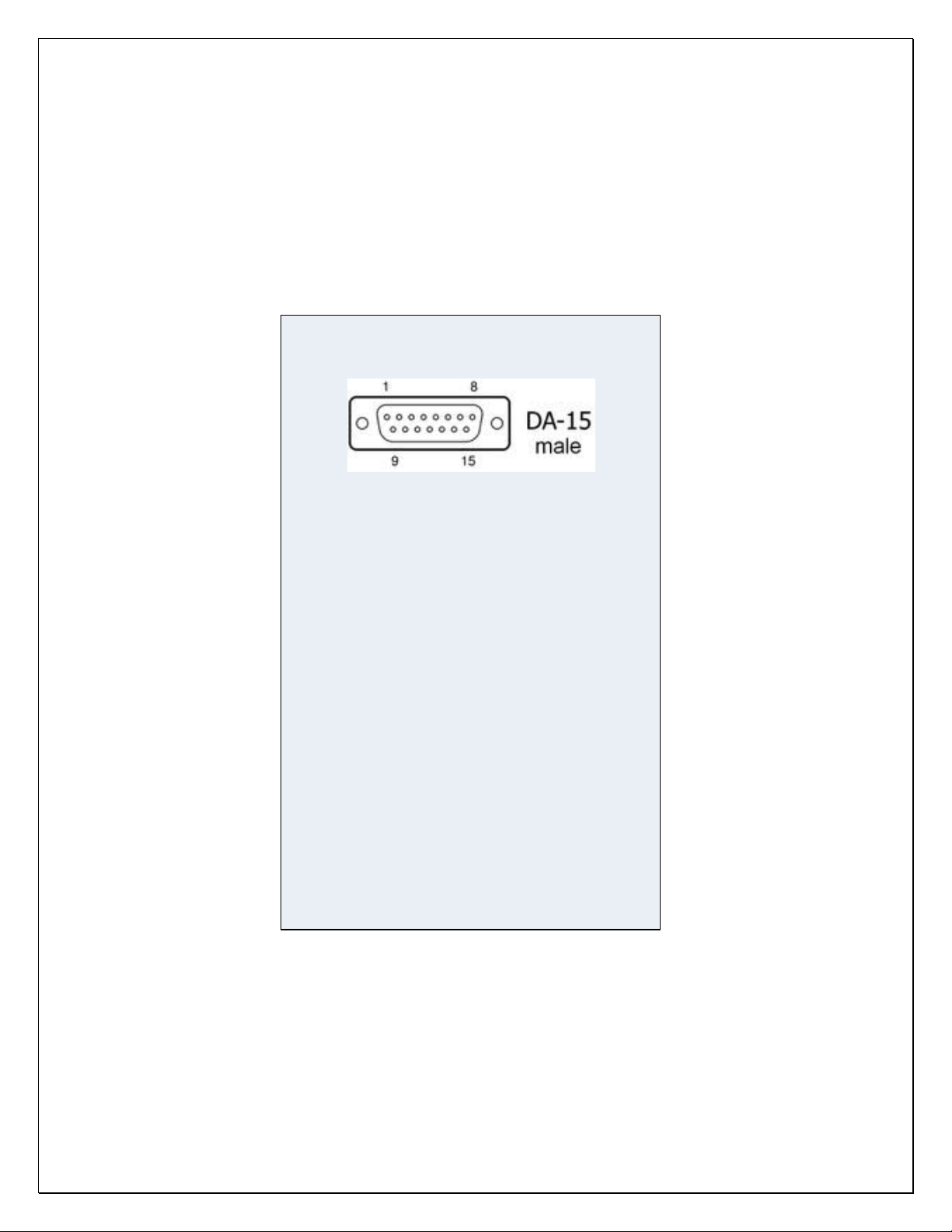
Wiring connector detail:
Male on IBBS unit
Female on aircraft wiring harness
View from back of aircraft wiring harness connector
Pin # Function
5 PWR + in, charge, sensing
2 Batt-info
3 Low Volt Warn
12 Output
13 Output
14 Output
15 Output
6 Pwr +, pass-thru input
1 Enable- backup switch
9 Ground
10 Ground
11 Ground
15 pin Male Dsub on unit
7 Pwr +, pass-thru input
8 Pwr +, pass-thru input
4 Pwr +, battery heater
p/n 725.0002 REV 3.0 © 2023 TCW Technologies, LLC.
18
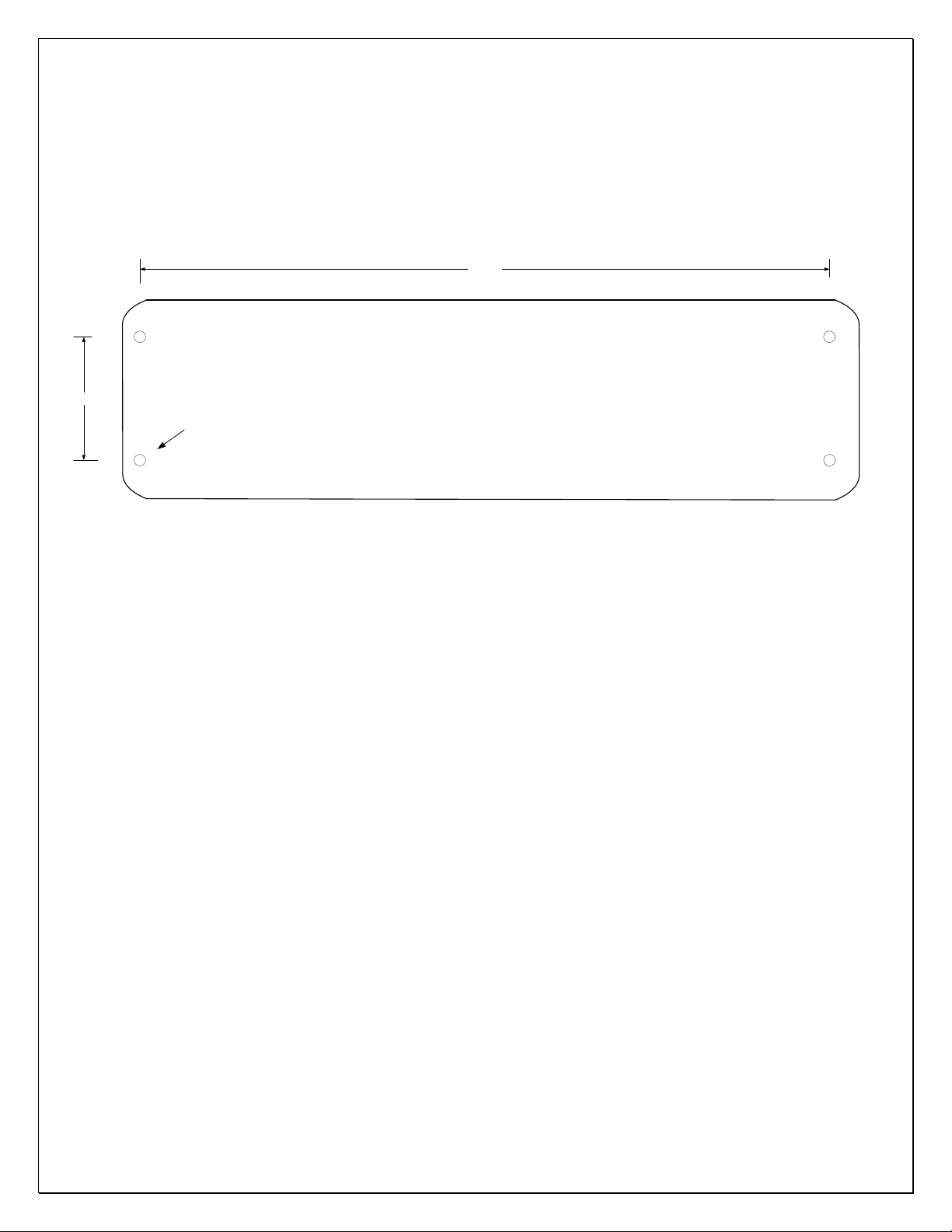
IBBS unit mounting footprint
11.16in.
2.00in.
Mounting holes
0.188" 4 plcs
All dimensions in inches
IBBS unit height = 3.2”
C.G at center of all axis
p/n 725.0002 REV 3.0 © 2023 TCW Technologies, LLC.
19
General Wiring Diagram
Main Aircraft Bus
Back-up Power Master
15 pin, female
Dsub connector
Back-up power output
Totalcombined load on all outputs = 5 amps
Batt-info to volt meter
Back-up power output
Back-up power output
20 awg
20 awg
20 awg
www.tcwtech.com
Emmaus, PA USA
IBBS-12V-3AH-CRT-V
Input: 13-16 volts DC
Output: 12 volts,5amps
INTEGRATED
Back-up Battery
SYSTEM
Back-up power output
20 awg
Main Aircraft Bus
charge/sense
pass-thru
Pin # Function
15 pin Male Dsub on unit
12 Output
13 Output
14 Output
15 Output
9 Ground
10 Ground
11 Ground
5 PWR + in, charge, sensing
2 Batt-info
3 Low Volt Warn
6 Pwr +, pass-thru input
1 Back-up master switch
7 Pwr +, pass-thru input
8 Pwr +, pass-thru input
4 PWR + in, battery heater
Pin # Function
+
-Low Voltage Warning LED,
25 mA max
battery heat

p/n 725.0002 REV 3.0 © 2023 TCW Technologies, LLC.
20
Battery
Master Solenoid
Wiring Diagram IBBS-12v-3ah-CRT-V
Equipment being
powered via IBBS
Example wiring for systems without back-up power inputs
Equipment without Back-up Power Input
Main Aircraft Bus
Back-up Power Master
Battery-Info
Back-up power output
20 awg
22 awg
22 awg
20 awg
20 awg
20 awg
1
6
9
10
2
5
12
main power input
15 pin, female
Dsub connector
3
+
-Low Voltage Warning LED
NOTE: Use redundant ground pins 9,10,11
Use redundant power inputs 6,7,8
based on load current of connected
equipment
7
11
8
13
14
15 output
output
output
www.tcwtech.com
Emmaus, PA USA
IBBS-12V-3AH-CRT-V
Input: 10-15 volts DC
Output: 12 volts,5amps
INTEGRATED
Back-up Battery
SYSTEM
4
Table of contents
Other TCW Technologies Batteries Pack manuals


