TDE MACNO 374T000600V User manual

Cod. MA00001E00 V_1.1
Accessories Tde Macno
User’s Manual
Remote Keypad


MA00001E00 V_1.1 1
INDEX
1INTRODUCTION ....................................................................................2
2SPECIFICATIONS..................................................................................2
3ENVIRONMENTAL SPECIFICATIONS ..................................................3
4DIMENSION DRAWINGS.......................................................................3
5ORDERING INFORMATION ..................................................................4
6CONNECTIONS .....................................................................................4
7INTERFACE ADAPTERS .......................................................................6
8PANEL MOUNTING................................................................................7
9OPERATIONS ........................................................................................7
9.1BEYOND LEGACY DISPLAY LIMITATIONS ..................................................................................... 8
9.2RUN SIGNALLING LED...................................................................................................................... 8
9.3MENU LOC (local parameters) ........................................................................................................... 8
9.4MENU FLB (fieldbus parameters)....................................................................................................... 9
9.5EXTENSION OF MENU APP............................................................................................................ 11
9.6ADDITIONAL CUSTOM KEYS AND LEDS ...................................................................................... 12

2MA00001E00 V_1.1
1 INTRODUCTION
The 374T000600V is a remotable display/keypad for OPD EXP and mini-OPD EXP drives.
The reliable RS485 industrial standard interface allow the keypad to be remotated up to several hundred
meters.
It implements a Modbus RTU protocol and behaves like a master on the RS485 bus with the possibility
to connect to several slave drives selecting the active drive (one at a time) by node address and bitrate.
The operator interface is the same available on the display/keypad integrated into the drive and extended to
manage the unique features, like the additional function keys and signalling leds or the built in storage
memory for drive’s parameter recipes and firmware (under development).
A brand new menù, LOC, is provided to manage LOCal (keypad) parameters and functions.
Also, the original operator interface has been updated in order to manage the new FLB menù, to access to
FieLdBus parameters, and the APP menù now allowes access to up 500 words of application’s extended
parameters (from E.100 up to E.599).
Optional interface adapter can be used in order to save the main RS485 interface of the drive (that then can
be used to connect with a controller for process automation or to a PC for configuring and monitoring by
OPDExplorer). In this case the connection between drive and remote keypad is limited just to point-to-point
(not multidrop).
2 SPECIFICATIONS
Power supply
Voltage 5 ÷ 30 Vdc (reversed polarity protected) to dedicated 3-poles connector on the back
side
Current < 200 mA (overall power supply < 1000 mW for any voltage within the range)
Communication
Data link interface RS-485, half duplex, DB9 male connector on back side with OPD EXP / mini-OPD
EXP standard pinout for direct “short” connection, inside polarization-termination
network available on connector for multidrop and/or “long” connection
Data link protocol Modbus RTU 8N1, master
Connection
capabilities
point-to-point or point-to-multipoint (multidrop) up to 128 devices with slave address
and bitrate selection (from 19.2 up to 115.2 kbps)
Standard operator interface
Display 7 segment, 5 digits + sign (red)
Standard keys 3 keys: select, increase, reduce
Standard indicators RUN led (green)
Access to fieldbus parameters by FLB menù, for Profibus and AnyBus configuration, status
and data mapping
Access to application extended parameters by extension of APP menù (parameters E100 up to E599)
Remote keypad management by LOC menù, for configuration parameters and functions

MA00001E00 V_1.1 3
Custom/extended operator interface (available for direct management by drive's application)
Application custom keys 3 keys
Application custom indicators 4 + 2 leds (3 yellow, 2 green, 1 red)
Advanced features
Non Volatile storage memory flash type, 2 MByte
NV memory functions
save/load local configuration parameters
upload/download of drive parameter recipes (under
development)
upload/download of drive firmware Core and Application
(under development)
access to the stored data from PC via RS485 interface
(under development)
3 ENVIRONMENTAL SPECIFICATIONS
Operating temperature: -10 ÷ 50 °C
Storage temperature: -20 ÷ 70 °C
Relative humidity: 10% ÷ 90% non condensing
Shock (operation): 10 to 25 Hz (X, Y, Z direction 2G 30 minutes)
CE/FCC: complies with EN 61000-4-4, EN 61000-6
Plastic enclosure case meets protection degree IP40. Front panel is already IP64 compliant then, when
mounted on panel, sealing gasket can be used to enhance the protection degree of overall installation up to
IP64.
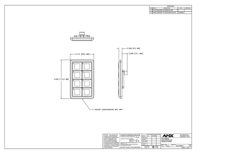
4 DIMENSION DRAWINGS

4MA00001E00 V_1.1
5 ORDERING INFORMATION
374T000600V remote keypad + 1.8m serial cable (DB9F-DB9M)
374I00100V external adapter for OPD EXP remote keypad interface (to free drive’s main RS485
interface)
374I00090V dummy keypad board adapter for mini-OPD EXP (to free drive’s main RS485
interface)
1KT4T0006A1 panel mounting kit (stirrup and screws for steady mounting on switchboard front
panel, gasket for IP65 sealing)
6 CONNECTIONS
CN1 is the data link connector: a DB9 male connector that hosts the RS485 signals with a pinout compatible
with OPD EXP and mini-OPD EXP RS485 interface for direct connection using a 1-to-1 serial cable.
CN1 Pin # Name Description
1 0V signal reference voltage
2 TX_RX + RS485 half duplex non inverting signal
(Tx / Rx) 2 -3 internally shorted
3 TX_RX +
4
5 Term + positive polarization/termination
6 TX_RX - RS485 half duplex inverting signal (Tx /
Rx) 6 – 7 internally shorted
7 TX_RX -
8
9 Term - negative polarization/termination
Please notice that the remote keypad RS485 interface is HALF DUPLEX so only 3 wires/signals (TX_RX+,
TX_RX-, 0V) can be connected between devices.Pins 2 and 3 are internally shortened and so also pins 6
and 7.In order to succesfully communicate with OPD EXP or mini-OPD EXP, that have FULL DUPLEX
RS485 interface, you have to shorten the same pins also at drive side or connect both pins 2, 3 and 6,7 (the
supplied serial cable use the latter).
2
6TX+
TX-
3
7RX+
RX-
10V
2
6TX_RX+
TX_RX-
3
7TX_RX+
TX_RX-
10V
RS485 at drive RS485 at keypad
2
6TX+
TX-
3
7RX+
RX-
10V
2
6TX_RX+
TX_RX-
3
7TX_RX+
TX_RX-
10V
RS485 at drive RS485 at keypad
The first cabling scheme is always recommended and it is mandatory in case of “long” and/or multidrop
connection.

MA00001E00 V_1.1 5
For “long” and/or multidrop connection is also mandatory to connect the polarization/termination
networks both on the first and last device on the bus chain: to do so, the pin 5 have to be tied with pin 2
(2 and 3 if the device is a drive) and the pin 9 have to be tied with pin 6 (6 and 7 if the device is a drive).
Shielded cable with twisted pairs (min AWG 22) is also recommended
To enhance EMI noise immunity, when
remote keypad is used with mini-OPD EXP,
it is also recommended to connect the
communication cable shield to ground using
the PE bar of the drive.
Also some level of noise reduction can be
achieved using a ferrite core (like FairRite
0431178281)
or, better, winding some turns of cable on
toroid (like Vacuumshmelze W516-03).
CN2 is the power supply connector.
CN1 Pin # Name Descripition
1 0V supply voltage reference
2 +V positive supply voltage
3 PE ground

6MA00001E00 V_1.1
Supply voltage has very wide input range (see specifications) and the keypad is protected against polarity
reversal. The builtin DC-DC regulator (switching type) assures high efficiency and almost constant power
comsumption over the whole voltage range.
Please notice that THERE IS NOT ISOLATION between power supply and the RS485 interface, so take
care during installation to avoid voltage contentions and ground loops.
7 INTERFACE ADAPTERS
The remote keypad was originally developed to directly connect to the RS485 interface (DB9F) available
both on OPD EXP and mini-OPD EXP, either in point-to-point or multipoint configuration.
Usually the RS485 interface of the drive is also used for connection to a PC and OPD Explorer
configurer/monitor utility in order do easily execute parametrization and commissioning. Sometimes the
RS485 interface is also used as main system fieldbus to connect to an automation controller (where more
powerfull fieldbus is not required or the tradeoff between performances and cost is anyway satisfied).
In these cases, the main RS485 of the drive can't be used anymore to connect the remote keypad as there
can be only one active Modbus master present on the bus (in order to avoid bus contentions).
The remote keypad can be configured (by param) to be “idle” (not active) on the bus, so it is possible to
physically connect the keypad and another master device on the same bus without conflicts but this setting is
intended to be temporary: i.e. to connect with OPD Explorer just the time to commissioning the slaves, then
disconnecting the PC with OPD Explorer and re-enabling the remote keypad.
For all other cases, where the remote keypad had to be permanently operative while the RS485 of the drives
is used by another master, the only solution is to use a different interface: for OPD EXP and mini-OPD EXP
are optionally available specific interface adapters that add a 2nd RS485 interface to the drive.
For mini-OPD EXP it is a “dummy keypad”
board that have to be mounted replacing
the standard integrated keypad (so there
will be no more integrated keypad on the
drive: there is just a single led to signal that
the drive has power supply). Insertion and
removing of internal keypad and dummy
keypad have to be done only when drive is
power off.

MA00001E00 V_1.1 7
For OPD EXP it is an external adapter that
connects to the “remote keypad” interface
in the front panel of the drive (the integrated
keypad is switched off when the adapter is
inserted: only one segment will remain lit up
to signal that the drive has power supply).
The external adapter can be
plugged/unplugged when the drive is power
on.
In both cases the adapter adds a new RS485 interface, half duplex, with DB9F connector, suitable for a
direct connection to a remote keypad.
Please notice that the added interface has constant (non changeable) slave address (1) and bitrate
(38.4kbps) and it is not isolated from the drive regulation board, so are possible only short point-to-point (no
multidrop) connections. Of course, the 2nd RS485 interface can be used also to connect to a different
master: you can for example connect an automation controller on the main interface and use 2nd interface to
connect to OPD Explorer for commissioning (keep in mind address and bitrate limitation).
8 PANEL MOUNTING
Follow these steps to mount the remote keypad on a switchboard front panel, using the optional kit:
1. remove the 2 screws from the backside of remote keypad
2. apply the sealing gasket to the channel presents along the side of the keypad frame
3. position the remote keypad on the panel
4. apply the stirrup to the backside of remote keypad securing it by the supplied screws
5. fasten the remote keypad to the panel using the screws on the wings of the stirrup till the sealing
gasket is fully pressed between keypad frame and panel
9 OPERATIONS
At power on all digit segments and signalling leds are briefly lit up to for checking.
Then the remote keypad try to communicate with the selected slave at the selected bitrate: if the slave
replies the display show” during the downloading of format tables and then the keypad goes “on-line”
allowing access to the remote drive.

8MA00001E00 V_1.1
The Operator Interface is almost the same available by the keypad integrated into the OPD EXP or mini-
OPD EXP drives, with same menus and navigation/editation key sequences and combinations (please refer
to the drive User Manual for further information about the standard operator interface).
Note that the operator Interface of the drive is available only when there is communication between remote
keypad and the drive.
If the physical connection is broken or the drive is powered off or Modbus node address and bitrate are
mismatched then the keypad can't succesfully communicate with a slave drive and then only the local menu
(LOC) is available.
As soon as the communication is re-establish and the remote keypad has completed the download of the
format tables (displaying”) all other features of drive operator interface become available.
Relevant differencies from standard operator interface are described in following sections.
9.1 BEYOND LEGACY DISPLAY LIMITATIONS
In the keypad integrated into the drive, for compatibility with the old hardware devices that have only 4 ¾
digits, the name of parameters from P100 up to P199 is represented inserting the “P” between the hundreds
and the rest of the index: ie P100 is displayed as “” and P199 is displayed like “”.
The remote keypad has a display with 5 full digits plus sign and doesn't have to grant compatibility with
legacy devices so the parameter name representation is more user friendly: now the whole parameter index
(either 2 or 3 digits) follows the parameter letter. So, using the same examples as before, P100 is displayed
as “” and P199 is displayed as “”.
For the same reason, the keypad integraded into the drive can't manage parameters with index greather
than 199 (it can't be represented at all) while with the remote keypad can show indexes up to 999.This is
useful in the managing of the extension of APP menu with the access to applicantion extra parameters: E100
up to E600.
Again, in the integrated keypad, values greather than “” or less than “-” can't be displayed so “ ”
and “ ” are displayed in their place.With remote keypad this limitation is removed and then values up to
99999 and down to -99999 can be displayed.
9.2 RUN SIGNALLING LED
The leftmost signalling led (green color), above the display, is provided to indicate the RUN status of the
connected drive, as the remote keypad could be far away from the drive or related motor and so this status
could be not manifest.This is also useful if the remote keypad is showing one of internal sizes values or a
digital input or output status: in this cases the operator interface doesn't automatically came back to the
stop/run status displaying (status of rest) but continues to show the selected value and so, again, the run
status could be not manifest.
9.3 MENU LOC (LOCAL PARAMETERS)
LOC menu refers to parameters and functions related to the remote keypad itself: they are managed locally
and normally don't affect the connected drive. They are also saved locally (when applicable) to a built in
Non Volatile Memory (NVM) in order to keep parametrization when power supply is switched off.
LOC menu is always accessible by remote keypad operator interface, even when connection to a slave is
missing.

MA00001E00 V_1.1 9
Name Description Min Max Default Notes
L.00 slave address to query 0 247 1 0 →BUS IDLE
L.01 bitrate 0 3 0
0 = 19.2kbps, 1 = 38.4kbps, 2=
57.6kbps, 3 = 115.2kbps
L.02 save to NVM 0 1 0
(1)
L.03 reload from NVM 0 1 0
(1)
L.04 load defaults 0 1 0(1)
L.05 setup for drive 2nd RS485
interface 0 1 0(1) equal to set L.00 = 1, L.01 = 1
Notes: (1) – parameter value auto reverts to 0 and is not saved to NVM
9.4 MENU FLB (FIELDBUS PARAMETERS)
FLB menu refers to parameters related to Fieldbuses management that was previusly accessible only by
OPD Explorer as they weren't associated to any “standard” parameter, connection or extra parameter and so
not accessible by keypad. Now they are grouped in this new menu, as listes in following tables, and so they
can be viewed and changed (if not read-only) by keypad.
As there are no format tables for these parameter, an abitrary format was assigned to each parameter based
on the use/meaning. For many of them, also, a HEX a decimal representation was choosed to show and edit
raw 16bit data value.
Notice that all parameters in FLB menu are not protected by any key nor by run status so they can be
changed at any time. Also, be aware that some parameter related to the configuration of fieldbuses take
effect only at power on so changes become effective only after saving and cycling the power supply.
Parameters related to configuration of Profibus DP and Anybus CC
Name OPD Explorer name OPD Explorer
description Min Max Default UM
F.00 NODE_SLAVE_ADDR Slave address 0 255 0
F.01 NODE_BAUD_RATE Node baudrate 0000 FFFF 0000 HEX
F.02 DATA_CONSISTANCE Data consistance 0 1 0
F.03 EN_ACYCLIC_DATA Enable acyclic data 0 1 1
F.04 EN_BIG_ENDIAN Most significant bytes in
multi-byte data types 0 1 1
F.05 PDP_SETUP_DATA Old Profibus DP setup
data 0000 FFFF 0000 HEX
F.06 FLDB_ERROR_CODE Fieldbus error code 0000 FFFF
(1)
HEX
F.07 FLDB_STATE Fieldbus state 0000 FFFF
(1)
HEX
Notes: (1) - read only
Parameters related to configuration of Anybus CC only
Name OPD Explorer name OPD Explorer description Min Max Default UM
F.08 IP_ADDR_00 Anybus IP Address 00 0 255 192
F.09 IP_ADDR_01 Anybus IP Address 01 0 255 168
F.10 IP_ADDR_02 Anybus IP Address 02 0 255 0

10 MA00001E00 V_1.1
F.11 IP_ADDR_03 Anybus IP Address 03 0 255 0
F.12 SUBNET_MASK_00 Anybus Subnet Mask 00 0 255 255
F.13 SUBNET_MASK_01 Anybus Subnet Mask 01 0 255 255
F.14 SUBNET_MASK_02 Anybus Subnet Mask 02 0 255 255
F.15 SUBNET_MASK_03 Anybus Subnet Mask 03 0 255 0
F.16 GATEWAY_00 Anybus Gateway 00 0 255 0
F.17 GATEWAY_01 Anybus Gateway 01 0 255 0
F.18 GATEWAY_02 Anybus Gateway 02 0 255 0
F.19 GATEWAY_03 Anybus Gateway 03 0 255 0
F.20 DHCP Anybus DHCP 0 1 1
F.21 ANYBUS_EN Anybus module enabled 0000 FFFF
(1)
HEX
F.22 ANYBUS_STATE Anybus module state 0000 FFFF
(1)
HEX
Notes: (1) - read only
Parameters related to data exchange mapping of Profibus DP and Anybus CC
Name OPD Explorer name OPD Explorer description Min Max Default UM
F.23 MAP_ERROR_CODE Mapping Error Code 0000 FFFF
(1)
HEX
F.24 MAP_ERROR_OBJ Mapping Error Object 0000 FFFF
(1)
HEX
F.25 RX0_INDEX Receive Object0 Index 0000 FFFF 0000 HEX
F.26 RX0_SUB_INDEX Receive Object0 Sub-Index 0000 FFFF 0000 HEX
F.27 RX1_INDEX Receive Object1 Index 0000 FFFF 0000 HEX
F.28 RX1_SUB_INDEX Receive Object1 Sub-Index 0000 FFFF 0000 HEX
F.29 RX2_INDEX Receive Object2 Index 0000 FFFF 0000 HEX
F.30 RX2_SUB_INDEX Receive Object2 Sub-Index 0000 FFFF 0000 HEX
F.31 RX3_INDEX Receive Object3 Index 0000 FFFF 0000 HEX
F.32 RX3_SUB_INDEX Receive Object3 Sub-Index 0000 FFFF 0000 HEX
F.33 RX4_INDEX Receive Object4 Index 0000 FFFF 0000 HEX
F.34 RX4_SUB_INDEX Receive Object4 Sub-Index 0000 FFFF 0000 HEX
F.35 RX5_INDEX Receive Object5 Index 0000 FFFF 0000 HEX
F.36 RX5_SUB_INDEX Receive Object5 Sub-Index 0000 FFFF 0000 HEX
F.37 RX6_INDEX Receive Object6 Index 0000 FFFF 0000 HEX
F.38 RX6_SUB_INDEX Receive Object6 Sub-Index 0000 FFFF 0000 HEX
F.39 RX7_INDEX Receive Object7 Index 0000 FFFF 0000 HEX
F.40 RX7_SUB_INDEX Receive Object7 Sub-Index 0000 FFFF 0000 HEX
F.41 RX8_INDEX Receive Object8 Index 0000 FFFF 0000 HEX
F.42 RX8_SUB_INDEX Receive Object8 Sub-Index 0000 FFFF 0000 HEX
F.43 RX9_INDEX Receive Object9 Index 0000 FFFF 0000 HEX
F.44 RX9_SUB_INDEX Receive Object9 Sub-Index 0000 FFFF 0000 HEX
F.45 TX0_INDEX Transmit Object0 Index 0000 FFFF 0000 HEX

MA00001E00 V_1.1 11
F.46 TX0_SUB_INDEX Transmit Object0 Sub-Index 0000 FFFF 0000 HEX
F.47 TX1_INDEX Transmit Object1 Index 0000 FFFF 0000 HEX
F.48 TX1_SUB_INDEX Transmit Object1 Sub-Index 0000 FFFF 0000 HEX
F.49 TX2_INDEX Transmit Object2 Index 0000 FFFF 0000 HEX
F.50 TX2_SUB_INDEX Transmit Object2 Sub-Index 0000 FFFF 0000 HEX
F.51 TX3_INDEX Transmit Object3 Index 0000 FFFF 0000 HEX
F.52 TX3_SUB_INDEX Transmit Object3 Sub-Index 0000 FFFF 0000 HEX
F.53 TX4_INDEX Transmit Object4 Index 0000 FFFF 0000 HEX
F.54 TX4_SUB_INDEX Transmit Object4 Sub-Index 0000 FFFF 0000 HEX
F.55 TX5_INDEX Transmit Object5 Index 0000 FFFF 0000 HEX
F.56 TX5_SUB_INDEX Transmit Object5 Sub-Index 0000 FFFF 0000 HEX
F.57 TX6_INDEX Transmit Object6 Index 0000 FFFF 0000 HEX
F.58 TX6_SUB_INDEX Transmit Object6 Sub-Index 0000 FFFF 0000 HEX
F.59 TX7_INDEX Transmit Object7 Index 0000 FFFF 0000 HEX
F.60 TX7_SUB_INDEX Transmit Object7 Sub-Index 0000 FFFF 0000 HEX
F.61 TX8_INDEX Transmit Object8 Index 0000 FFFF 0000 HEX
F.62 TX8_SUB_INDEX Transmit Object8 Sub-Index 0000 FFFF 0000 HEX
F.63 TX9_INDEX Transmit Object9 Index 0000 FFFF 0000 HEX
F.64 TX9_SUB_INDEX Transmit Object9 Sub-Index 0000 FFFF 0000 HEX
Notes: (1) - read only
9.5 EXTENSION OF MENU APP
The menu APP (APPlication parameters) allowes access to the parameters that every application defines:
parameters form E00 up to E99 that often in the documentation and also in OPD Explorer are referred as
parameters from P200 up to P299. That's enough for almost all the applications but some ones need to
define more parameters and data. For this purpose the drive supply a specific memory area that till now was
accessible only by OPD Explorer.
In the remote keypad the APP menu has been extended in order to allow access to this data: parameters
E100 up to E599 now refers to the first 500 16bit words data of application extra parameters.
Often an application need to define 32bit wide values: in this cases the keypad split the value and accesses
as 2 separate parameters (each 16bit wide). Conventionally, a 32bit value takes two parameters with
sequential indexes, starting from a even index: the parameter with the lower index (even) contains the least
significant word while the parameter with higher index (odd) contains the most significant word.
As no format information are available for these extra parameters, all values are represented in HEX a
decimal format. Also, for these parameters there is no key or run protection so they can be changed at any
time: refer to the application documentation to know if the modified values take action immediately or need a
power cycling.
Note that in the range E00 – E99 (application parameters) the remote keypad shows only parameters really
existing and managed by the application, while parameters in the range E100 – E599 (application extra
parameters) are always present, even if the installed application don't define and use them all or part of.

12 MA00001E00 V_1.1
Menu APP: application parameters
Name OPD Explorer
name
OPD Explorer
description Min Max Default UM
E.00
(1)
(1)
(1)
(1)
(1)
(1)
...
(1)
(1)
(1)
(1)
(1)
(1)
E.99
(1)
(1)
(1)
(1)
(1)
(1)
Notes: (1) – depends on installed application
Menu APP: application extra parameters
Name OPD Explorer
name
OPD Explorer
description Min Max Default UM
E.100
(1)
(1)
0000 FFFF
(1)
HEX
...
(1)
(1)
0000 FFFF
(1)
HEX
E.599
(1)
(1)
0000 FFFF
(1)
HEX
Notes: (1) – depends on installed application
9.6 ADDITIONAL CUSTOM KEYS AND LEDS
The remote keypad provide 3 additional keys referred as “F1” to “F3” and 4 additional signalling leds referred
as “L1” to “L4” (up to 2 more keys and leds can be added on request).
The colour of the leds are:
L1 – yellow
L2 – yellow
L3 – yellow
L4 – green
These keys and leds aren't used by the operator interface so no functions and meanings are normally
associated with. They are available for direct management by the drive application and so can be assigned
to application customized actions and signallings.
The remote keypad simply notify the status of the additional keys to the drive and retrieve the status of the
leds from the drive.
Please refer to the installed application documentation for the assigned actions and signalling (if any).


Via dell’Oreficeria, 41
36100 Vicenza - Italy
Tel +39 0444 343555
Fax +39 0444 343509
www.tdemacno.com
s.p.a. tecnologie digitali elettroniche
Table of contents


