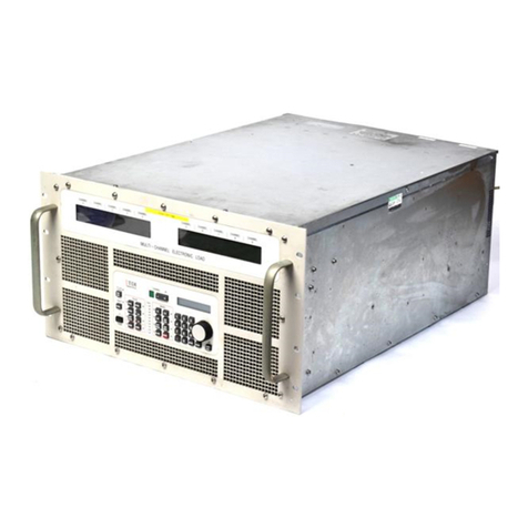
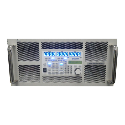
TDI TDI-Dynaload WCL488 Series Owner's manual

WCL488 Series
Water Cooled
Electronic Loads
Operation & Programming Manual
TDI-Dynaload®Division
Document Number 402828 — Revision B1

© 2003 TDI-Dynaload — All Rights Reserved.
The copyright laws of the United States and other countries protect this material. It may not be
reproduced, distributed, or altered in any fashion without the expressed written consent of TDI-
Transistor Devices, Inc.
Disclaimer
The contents of this document, including all specifications, are subject to change without notice.
Mandatory Customer Information
Federal Communications Commission (FCC) Statement
NOTE: This equipment has been tested and found to comply with the limits for a Class A digital
device, pursuant to Part 15 of the FCC Rules. These limits are designed to provide reasonable
protection against harmful interference when equipment is operated in a commercial
environment. This equipment generates, uses, and can radiate radio frequency energy; and, if not
installed and used in accordance with the instruction manual, may cause interference to radio
communications. Operation of this equipment in a residential area may cause harmful interference
in which case the user will be required to correct the interference at their expense.
Trademarks
Dynaload is a registered trademark of Transistor Devices, Inc.
Ordering Information
The ordering number for this document is 402828. To order this document, contact:
TDI-Dynaload Division
36A Newburgh Road
Hackettstown, NJ 07840
Telephone: (908) 850-5088
Facsimile: (908) 850-0679
Online Availability
To find out more about TDI and our products, visit us on the web at: http://www.tdipower.com/ or
visit TDI-Dynaload directly at: http://www.tdipower.com/dynaload/.
Customer Services
For technical assistance regarding our products, contact the following:
Sales Inquires
Dynaload Sales Manager
Telephone: (908) 850-5088
Facsimile: (908) 850-0679
Customer Service and Repairs
Dynaload Customer Service Department
Telephone: (908) 850-5088
Facsimile: (908) 850-3645

TDI-Dynaload Division WCL488 Series Water Cooled Electronic Loads
Operation & Programming Manual
402828, Rev. B1 Page i
Contents
Chapter 1 — Overview................................................................................... 1
Introduction............................................................................................................1
Modes of Operation ...............................................................................................2
Constant Current Mode .............................................................................................2
Constant Resistance Mode.........................................................................................3
Constant Voltage Mode.............................................................................................3
Constant Power Mode ...............................................................................................4
Pulse Mode ................................................................................................................4
Full Scale Range Switching.......................................................................................4
WCL488 Front Panel Features and Controls .....................................................5
Chapter 2 — Installation and Wiring.............................................................. 7
Operator Safety Instructions and Symbols .........................................................7
Cooling Connections and Requirements..............................................................8
Thermal Transfer Characteristics...............................................................................8
Special Information for Ethylene Glycol Users.......................................................11
WCL488 Typical Rear Panel Connections........................................................12
WCL488 Rear Panel Electrical Connections ....................................................13
WCL488 E+ and E– Power Input Buses .................................................................13
WCL488 E+ and E–Wiring Tips.......................................................................13
WCL488 The “IEEE-488” Connector (RS232 Optional) .......................................14
WCL488 AC Input ..................................................................................................14
WCL488 Input Voltage Selector .............................................................................14
WCL488 Fuse Replacement....................................................................................14
WCL488 AC Input Wiring Tips.........................................................................15
WCL488 Slave Communication Connector ............................................................15
WCL488 Slave Communication Connector Wiring...........................................15
WCL488 UV (Undervoltage Lockout) Switch........................................................15
WCL488 Relay Connector ......................................................................................16
WCL488 Chassis Ground Connection ....................................................................16
The WCL488 Terminal Block and Terminal Block Connections ...........................17

WCL488 Series Water Cooled Electronic Loads
Operation & Programming Manual
TDI-Dynaload Division
Page ii 402828, Rev. B1
CS (Current Sample)...........................................................................................17
REM (Remote or External Programming)..........................................................18
SYN (Synchronized Output Signal) ...................................................................18
EN (Remote Enable)...........................................................................................18
S– and S+ (Voltage Sense) .................................................................................18
S– and S+ (Voltage Sense) Wiring Tips ......................................................18
E– and E+ (Input) ...............................................................................................19
WCL488 Terminal Block Connections Optional Equipment Wiring.................20
Recommended Operating Procedure.................................................................21
Operating Mode Guidelines................................................................................22
CI — Constant Current Mode (Basic Mode)...........................................................22
CR — Constant Resistance Mode (Basic Mode).....................................................22
CV — Constant Voltage Mode (Basic Mode).........................................................23
CP — Constant Power Mode (Basic Mode)............................................................23
Short Circuit ............................................................................................................23
MEM — Memory Recall Locations........................................................................23
Manual Adjust .........................................................................................................23
Remote Programming..............................................................................................23
Local Control...........................................................................................................24
Fault Indicators........................................................................................................24
Undervoltage Lockout.............................................................................................25
Programmable Under Voltage.................................................................................25
Menu Commands.....................................................................................................26
Current Limit Setting..........................................................................................27
Range Switching and Current Limit Set Point....................................................27
Voltage Limit Setting .........................................................................................27
Power Limit Setting............................................................................................27
Slew Rate Adjustment ........................................................................................27
Encoder Resolution Setting ................................................................................27
Front Panel Configuration Memory Set .............................................................28
Front Panel Lock ................................................................................................28

TDI-Dynaload Division WCL488 Series Water Cooled Electronic Loads
Operation & Programming Manual
402828, Rev. B1 Page iii
IEEE Address Setting .........................................................................................28
Password Change................................................................................................28
SF/SS (Slew Range) ...........................................................................................28
Number Of Pulses...............................................................................................28
Terminator (CR/CR-LF).....................................................................................28
LCD Contrast Adjust..........................................................................................29
Select Amps/Volt Or Ohms................................................................................29
Check Firmware Revision ..................................................................................29
Programmable UV Level....................................................................................29
Pulse Mode ..............................................................................................................29
Manual Operation...............................................................................................29
IEEE-488 Programming .....................................................................................30
Effects of Cable Inductance On Pulse Loading.......................................................31
Effects Of Cable Length......................................................................................32
Current Oscillation ..................................................................................................32
Line Loss .................................................................................................................32
Transconductance....................................................................................................34
Location, Airflow, Maintenance..............................................................................34
WCL488/WCS Water Cooled Load Systems ....................................................35
Synchronized Paralleling.........................................................................................35
Slave Configuration.................................................................................................36
Water Cooled Load Systems Components and Wiring ...........................................37
WCS Front Panel Features and Controls..........................................................39
WCS Rear Panel Electrical Connections...........................................................40
WCS E+ and E– Power Input Buses .......................................................................40
WCS E+ and E–Wiring Tips .............................................................................40
WCS AC Input ........................................................................................................41
WCS Input Voltage Selector ...................................................................................41
WCS AC Input Wiring Tips ...............................................................................41
WCS Fuse Replacement ..........................................................................................42
WCS Slave Communication Connector ..................................................................42
WCS Slave Communication Connector Wiring .................................................42

WCL488 Series Water Cooled Electronic Loads
Operation & Programming Manual
TDI-Dynaload Division
Page iv 402828, Rev. B1
WCS UV (Undervoltage Lockout) Switch..............................................................42
WCS Relay Connector.............................................................................................43
WCS Chassis Ground Connection...........................................................................44
Slave Bit Identifier Switches ...................................................................................44
Chapter 3 — IEEE-488 Commands and Programming................................ 45
Introduction..........................................................................................................45
IEEE-488 Bus Subsets .........................................................................................45
Data Separators....................................................................................................46
Program Line Terminators.................................................................................46
Numerical Data Formats.....................................................................................46
Numerical Data Units ..........................................................................................46
Power-on Defaults................................................................................................48
Commands............................................................................................................49
Queries ..................................................................................................................49
Command and Queries Listed Alphabetically ..................................................50
Commands and Queries Listed by Category ....................................................53
Configuration......................................................................................................53
Identification.......................................................................................................53
Limit Control ......................................................................................................53
Load Control.......................................................................................................53
Operation Modes ................................................................................................54
Pulsing ................................................................................................................54
Pulsing Level Parameters....................................................................................55
Readbacks...........................................................................................................55
Slew Rate Commands.........................................................................................55
Status Related Commands ..................................................................................56
Miscellaneous .....................................................................................................56
Detail Language Elements...................................................................................57
AV1 Amps/Volt Pulsing Base Level ...................................................................57
AV2 Amps/Volt Pulsing Peak Level ...................................................................58

TDI-Dynaload Division WCL488 Series Water Cooled Electronic Loads
Operation & Programming Manual
402828, Rev. B1 Page v
AV?.....................................................................................................................58
AVH Amps/Volt High .........................................................................................58
AVL Amps/Volt Low...........................................................................................59
CI Constant Current ...........................................................................................59
CON? Condition register....................................................................................60
CP Constant Power.............................................................................................61
CR?.....................................................................................................................61
CRH Constant Resistance High..........................................................................61
CRL Constant Resistance Low ...........................................................................62
CV Constant Voltage..........................................................................................62
DU Duty Cycle....................................................................................................63
ERR? Error Register ..........................................................................................64
FQ Frequency .....................................................................................................65
I? Read Current ..................................................................................................65
I1 Constant Current Pulsing Base Level ............................................................66
I2 Constant Current Pulsing Peak Level ............................................................66
ID? Identification................................................................................................66
IL Current Limit .................................................................................................67
LAT Latch register .............................................................................................68
LOAD Load On/Off Control ..............................................................................69
LOCK Front Panel Lock ....................................................................................69
MODE? Operating Mode ...................................................................................70
MR Memory Recall.............................................................................................71
MS Memory Save................................................................................................71
P? Read Power ...................................................................................................71
P1 Constant Power Pulsing Base Level..............................................................72
P2 Constant Power Pulsing Peak Level .............................................................72
PL Power Limit...................................................................................................72
R1 Constant Resistance Pulsing Base Level.......................................................73
R2 Constant Resistance Pulsing Peak Level ......................................................73
RNG Range.........................................................................................................74
RST Reset ...........................................................................................................75
SBE Summary Bit Enable register......................................................................76

WCL488 Series Water Cooled Electronic Loads
Operation & Programming Manual
TDI-Dynaload Division
Page vi 402828, Rev. B1
SDN Shutdown register ......................................................................................77
SF Slew Fast .......................................................................................................78
SR Slew Rate......................................................................................................78
SRQ Service Request Register............................................................................79
SS Slew Slow ......................................................................................................80
STA? Status Register..........................................................................................81
SW Square Wave Pulsing ...................................................................................82
T1 Pulsing Base Time.........................................................................................82
T2 Pulsing Peak Time.........................................................................................83
TEXT Text Mode ................................................................................................83
UV Under Voltage..............................................................................................84
V? Read Voltage .................................................................................................84
V1 Constant Voltage Pulsing Base Level ...........................................................85
V2 Constant Voltage Pulsing Peak Level...........................................................86
VER? Version .....................................................................................................86
VL Voltage Limit ................................................................................................86
WF Waveform.....................................................................................................87
XM External Modulation ...................................................................................88
Status and Error Register ...................................................................................89
Glossary ........................................................................................................ 91
Appendix A — List of Commands............................................................. 106
Appendix B — List of Queries................................................................... 107
Appendix C — WCL488 Outline Drawings .............................................. 108
Appendix D — WCS Outline Drawings .................................................... 109
Appendix E — Flow Control Servo Installation ........................................ 110
Appendix F — DC Power Contactor Recommended Installation.............. 111
Appendix G — Troubleshooting Guide ..................................................... 112

TDI-Dynaload Division WCL488 Series Water Cooled Electronic Loads
Operation & Programming Manual
402828, Rev. B1 Page vii
Appendix H — Specifications by Model.................................................... 119
Figures
Figure 1. Constant Current Mode.....................................................................................................2
Figure 2. Constant Resistance Mode................................................................................................3
Figure 3. Constant Voltage Mode ....................................................................................................3
Figure 4. Constant Power Mode.......................................................................................................4
Figure 5. WCL488 Front Panel Features and Controls....................................................................5
Figure 6. Thermal Transfer Characteristics (Rate/Temperature) — Inlet Temperature 10ºC..........9
Figure 7. Thermal Transfer Characteristics (Rate/Temperature) — Inlet Temperature 20ºC........10
Figure 8. Recommended Power De-rating Versus Flow Rate for Different Ethylene
Glycol Levels ..................................................................................................................11
Figure 9. WCL488 Typical Rear Panel Connections.....................................................................12
Figure 10. WCL488 Rear Panel Detail...........................................................................................13
Figure 11 WCL488. AC Input, Fuse and Input Voltage Selector ..................................................14
Figure 12. WCL488 UV Switch Detail ..........................................................................................16
Figure 13. WCL488 Relay Connector and Chassis Ground Connection .......................................16
Figure 14. WCL488 Terminal Block Detail...................................................................................17
Figure 15. WCL488 Terminal Block Connections.........................................................................17
Figure 16. WCL488 Terminal Block Connections Optional Equipment Wiring...........................20
Figure 17. Slave Bit Identifier Switches.........................................................................................36
Figure 18. Water Cooled Load Systems Wiring Diagram..............................................................38
Figure 19. WCS Front Panel Features and Controls ......................................................................39
Figure 20. WCS Rear Panel Detail.................................................................................................40
Figure 21. WCS. AC Input, Fuse and Input Voltage Selector........................................................41
Figure 22. WCS UV Switch Detail ................................................................................................43
Figure 23. WCS Relay Connector and Chassis Ground Connection .............................................43
Figure 24.WCS Slave Bit Identifier Switches................................................................................44
Figure 25. Load Status Structure....................................................................................................90
Tables
Table A. WCL488 Front Panel Features and Controls.....................................................................5

WCL488 Series Water Cooled Electronic Loads
Operation & Programming Manual
TDI-Dynaload Division
Page viii 402828, Rev. B1
Table B. Equipment Safety Symbols................................................................................................7
Table C. Outlet Temperature with 10ºC Inlet...................................................................................9
Table D. Outlet Temperature with 20ºC Inlet ................................................................................10
Table E. WCL488 AC Input Power Requirements ........................................................................14
Table F. Major and Minor Fault Indicators....................................................................................24
Table G. Menu Commands.............................................................................................................26
Table H. Wire Gauge/Ampere Rating Reference Table.................................................................33
Table I. Input Power Requirements................................................................................................41
Table J. Bus Subset Capabilities ....................................................................................................45
Table K. Numerical Data Formats..................................................................................................46
Table L. Numerical Data Units.......................................................................................................47
Table M. Power-on Defaults ..........................................................................................................48
Equations
Equation 1. Establishing Maximum Cable Length.........................................................................31
Equation 2. Formula to Establish Capacitor Requirements............................................................32

TDI-Dynaload Division WCL488 Series Water Cooled Electronic Loads
Operation & Programming Manual
402828, Rev. B1 Page 1
Chapter 1 — Overview
Introduction
The WCL488 Water Cooled Electronic Loads are ideal for high current/high power battery,
power supply and fuel cell testing. Standard systems from 12kW to 120kW are configured using
12kW standard products in a master/slave configuration. Each 12kW unit is rated at 0-100V or 0-
400V, 0-1000A (1200A for the 50V model), not to exceed 12,000W. Larger systems are available
upon request.
The WCL488 master unit measures 5-1/4 inches high and the slave unit measures 3-1/2 inches
high and both fit into a standard 19-inch wide equipment rack. The compact size of the units and
our unique plumbing design allows 120kW of power dissipation in a single 60 high rack.
Systems may be upgraded by adding slave units. The manifold plumbing design and complete
DC bus structure allow for simple upgrade in the field.
Individual units' electrical inputs and water inlet and output connections are located on the rear of
each unit. Single connections are provided for systems unless otherwise specified.
Standard features for the WCL488 Series include the following:
Operation below 1 Volt at 10,000 Amps (50 Volt model only)
Five modes of operation: Constant Current, Constant Resistance, Constant Power,
Constant Voltage, Pulse Mode
Full Scale Range Switching: When a scale is selected, it changes the controls and
instrumentation to correspond with the selected scale, for increased resolution and
accuracy.
Synchronized paralleling creates larger systems controlled as a single unit
Automated flow regulation to eliminate condensation
Lab View drivers are available for computer control
Self configuring based on number of slaves in use
Units available include:
50 Volts, 1200 Amps, 12000 Watts
100 Volts, 1000 Amps, 12000 Watts
400 Volts, 1000 Amps, 12000 Watts.
Highest Density Solution: Complete 120kW system only 60 inches tall
Constant Current, Resistance, Voltage, Power
Modular design using standard building blocks

WCL488 Series Water Cooled Electronic Loads
Operation & Programming Manual
TDI-Dynaload Division
Page 2 402828, Rev. B1
Low water flow (3gpm at 10°C / 12kW)
Range switching for increased resolution and accuracy
WCL488 Dimensions: 19 inches W x 5.22 inches H x 24 inches D
WCS Dimensions: 19 inches W x 3.47 inches H x 24 inches D.
The Dynaload modes of operation are described in the sections that follow and are thoroughly
detailed in Chapter 2 — Installation and Wiring.
Modes of Operation
The Dynaload is a precision instrument that simulates DC loads to test power supplies,
generators, servo systems, batteries and similar DC sources.
The WCL488 series provides four basic modes of operation: Constant Current, Constant
Resistance, Constant Voltage, Constant Power and Pulse Mode. Complete control is available
through the full feature front panel, IEEE-488 bus or optional RS232 interface. A 0-10V analog
programming input is also available in all of the four modes of operation. The connections for
IEEE-488 and analog programming are located at the rear of the unit. Refer to Figure 1 through
Figure 4 and the four modes of operation explanations that follow.
Constant Current Mode
Referring to Figure 1, the Dynaload will sink the set current regardless of the input voltage.
Figure 1. Constant Current Mode
4 02 8 25-0 2-0 1 .C D R
V
Load
Current
Current Setting
Input Voltage
I

TDI-Dynaload Division WCL488 Series Water Cooled Electronic Loads
Operation & Programming Manual
402828, Rev. B1 Page 3
Constant Resistance Mode
Referring to Figure 2, the Dynaload will sink current linearly proportional to the input voltage.
This is set in Amps/Volt, (1/R), or ohms.
Figure 2. Constant Resistance Mode
Constant Voltage Mode
Referring to Figure 3, the Dynaload will sink the current required to maintain the voltage of the
source connected to it.
Figure 3. Constant Voltage Mode
4 02 8 25-0 2-0 2 .C D R
V
Load
Current
Slop e =
Resistance Setting
Input Voltage
I
4 02 8 25-0 2-0 3 .C D R
Load C urrent
Voltage
Setting
V
I
Input
Voltage

WCL488 Series Water Cooled Electronic Loads
Operation & Programming Manual
TDI-Dynaload Division
Page 4 402828, Rev. B1
Constant Power Mode
Referring to Figure 4, the Dynaload will sink the current required at its present input voltage to
maintain the desired power level.
Figure 4. Constant Power Mode
Pulse Mode
This mode can be used with any of the four preceding modes. Pulse mode is an enhancement that
allows for operation between two predefined levels of current, resistance, voltage or power.
Full Scale Range Switching
The WCL488 series provides selection of one of three full-scale input voltage ranges and one of
three full scale input current ranges. The full-scale voltage and current ranges may be selected in
any combination resulting in nine operational ranges per unit. These are selectable over the bus as
ranges (1 through 9 refers to IEEE-488 syntax section).
The selectable ranges provide increased resolution. For example: Setting 10 amps may be
difficult using the 1000 amp full scale. By selecting a lower full scale, 100 amps, the resolution of
the meters, IEEE-488 control, programming input and the current sample output are greatly
increased.
4 02 8 25-0 2-0 4 .C D R
V
Load
Current
Constant P ow er Setting
Input Voltage
I

TDI-Dynaload Division WCL488 Series Water Cooled Electronic Loads
Operation & Programming Manual
402828, Rev. B1 Page 5
WCL488 Front Panel Features and Controls
To better understand the features and controls of the front panel, refer to Figure 5 and Table A.
The item numbers in the figure directly correspond to the item numbers in the table.
Figure 5. WCL488 Front Panel Features and Controls
Table A. WCL488 Front Panel Features and Controls
Item
Number
Description
1AC Power (Power On, Power Off)
2IEEE-488 Local Select
3DC Load (On, Off)
4Pulse Mode Controls
RUN: Pulse Mode On/Off
PEAK: Sets peak amplitude of pulse
FREQ: Sets frequency of pulse
DUTY CYCLE: Sets duty cycle of pulse
tLO: Sets duration of the low portion of pulse
tHI: Sets duration of the high portion of pulse
4 02 82 8-02-2 3.C D R
5
6
7
9
10
11
12
13
4
3
2
15
14
17
16
1
K
K
8

WCL488 Series Water Cooled Electronic Loads
Operation & Programming Manual
TDI-Dynaload Division
Page 6 402828, Rev. B1
Item
Number
Description
5Voltmeter/Voltage Full Scale Range Selection*
6Voltmeter (4 digit)
7Ammeter/Current Full Scale Range Selection*
8Ammeter (4 digit. Includes two range indicators. AMPS displays actual current.
For K AMPS, multiply the display by 1000 for the actual current.)
9Wattmeter (4 digit. Includes two range indicators. WATTS displays actual power.
For K WATTS, multiply the display by 1000 for the actual power.)
10 Backlit Alphanumeric Display (This display indicates data input from the front
panel controls [range, mode, and setpoint as entered by the user]. This will also
display other data as selected through the menu selector.)
11 Manual Adjust Knob
12 Manual Adjust Enable
13 Keypad (for numerical entry)
14 Menu Select
15 MEM Preset (up to 10 configurations)
16 Mode Select
CI: Constant Current Mode Select
CV: Constant Voltage Mode Select
CP: Constant Power Mode Select
CR LOW: Constant Resistance (Low Ohm) Mode Select
CR HIGH: Constant Resistance (High Ohm) Mode Select
EXT PROG: Remote Programming Mode Select
SLAVE: Slave Detection
SHORT: Inactive on this product
17 Fault And Warning Status Indicators
SYS: System Fault Indicator
UV: Undervoltage Fault Indicator
OV: Overvoltage Fault Indicator
TEMP: Over Temperature Fault Indicator
I LIM: Current Limit Warning Indicator
P LIM: Power Limit Warning Indicator
SAT: Saturation Warning Indicator
MOD: Module Fault Warning Indicator
* The WCL488 Series offers the selectable full-scale ranges for current and voltage. When a
full scale is selected it changes the full scale of the meter, the current sample, the front panel
adjustments, IEEE controlled adjustments and the analog programming input. This provides an
increase in accuracy and resolution. There are three standard full-scale current ranges and three
standard full-scale voltage ranges.

TDI-Dynaload Division WCL488 Series Water Cooled Electronic Loads
Operation & Programming Manual
402828, Rev. B1 Page 7
Chapter 2 — Installation and Wiring
Operator Safety Instructions and Symbols
It is very important that these safety instructions and operation instructions are read and
understood prior to the installation and use of this electronic load. Failure to follow these basic
guidelines could result in serious injury or death.
This electronic load is inherently safe by design. It cannot produce any hazardous voltages or
currents; however, when in use it may expose the operator to the hazards of the DC source to
which the load is connected. This equipment is intended for use by trained personnel and there
are no operator serviceable parts inside. All service and calibration must be performed by
authorized personnel. Table B describes the safety symbols and their definitions. Safety symbols
are placed to ensure the safety of Dynaload operators and should never be covered or removed
from the equipment.
WARNING:
Ensure that all AC and DC power for both the load, the test source, and any
peripheral equipment are OFF prior to making any connections to the load.
Also ensure that the proper AC input range is selected before attaching the
line cord; and that the load selected is properly rated for the voltage and
current generated by the DC source; and that all connections are correct
and secure, and that all safety covers are in place before applying power.
If the unit is to be mounted, please consider the weight and position of the
equipment to prevent the rack from becoming top heavy. A top-heavy rack
can create a tip over hazard. All air intake and exhaust ports should be kept
clear of obstructions.
Table B. Equipment Safety Symbols
Symbols Definitions Publication Numbers
CAUTION, RISK OF ELECTRIC
SHOCK ISO 3864, No. B.3.6
CAUTION, REFER TO INSTRUCTION
MANUAL ISO 3864, No. B.3.1
EASILY TOUCHED HIGHER
TEMPERATURE PARTS ISO 3864

WCL488 Series Water Cooled Electronic Loads
Operation & Programming Manual
TDI-Dynaload Division
Page 8 402828, Rev. B1
Cooling Connections and Requirements
IMPORTANT:
Before using this product, you must fully understand the relationship
between the water temperature, flow rate, and power dissipation. Failure
to meet the cooling requirements could result in an unexpected system
shutdown or a catastrophic failure.
Also, users of ethylene glycol and similar products should refer to the
special section “Special Information for Ethylene Glycol Users” that
immediately follows this section.
The WCL Series of Electronic Loads requires a sustained flow of coolant in order to operate. The
load is protected against overtemperature through the use of a thermostat that will shut down the
load if the heat sink temperature exceeds 70ºC (158ºF). The unit is designed to operate to its full
power rating with a minimum flow rate of three gallons per minute (GPM) of coolant at 10ºC
(50ºF). Operation at other flow rates and inlet temperatures based on power dissipation can be
derived from the graphs (figures) and tables that follow in the next section, Thermal Transfer
Characteristics. If you are unsure about your requirements please consult the factory.
Each master load assembly or slave assembly has one inlet and one outlet water connection. They
are 1/2-inch NPT female thread. A multitude of adapters can be found at your local hardware
store if the connection size needs to be changed. Do not reduce the water lines below 3/8-inch
inner diameter, as improper water flow will result.
If you are using a “chiller” to regulate the water temperature, be sure to properly size the device
to match or exceed your cooling requirements. The specifications for the wattage capacity and
flow rates are provided from all chiller manufacturers. If your location can provide “processed
water” be sure the maximum pressure does not exceed 120 PSI.
Though the temperature graphs indicate that the load will operate to full power with only three
gallons per minute flow using 20ºC (68ºF) water, we recommend that the heat sink temperature
not exceed 60ºC (140ºF). This will provide a substantial margin for safety by lowering the stress
level on the power tray and extend the life of the product.
Thermal Transfer Characteristics
Figure 6 and Table C relate to operation at various flow rates with an inlet temperature of 10ºC,
based on power dissipation levels of 5, 8, 10, and 12 kilowatts. For the same type of operation
information with an inlet temperature of 20ºC, refer to Figure 7 and Table D.

TDI-Dynaload Division WCL488 Series Water Cooled Electronic Loads
Operation & Programming Manual
402828, Rev. B1 Page 9
Figure 6. Thermal Transfer Characteristics (Rate/Temperature) — Inlet Temperature 10ºC
Table C. Outlet Temperature with 10ºC Inlet
Outlet Temperature with 10ºC Inlet
Power Level
Flow Rate 5 kW 8 kW 10 kW 12 kW
3 GPM 22.1ºC 29.8ºC 35.6ºC 37.4ºC
4 GPM 20.3ºC 26.2ºC 30.1ºC 32.3ºC
5 GPM 18.3ºC 22.8ºC 26.7ºC 29.6ºC
M ax im u m A llo w ed O p era ting Tem p era tu re
12 kW
10 kW
8 kW
5 kW
Heatsink
Temperature
(ºC)
70
60
50
40
30
20 2.0 3.0 4.0 5.0 6.0 7.0
Flow R ate (G allons Per M inute) — W ater Tem perature 1 0ºC
4 02 8 28-0 2-0 1.C D R

WCL488 Series Water Cooled Electronic Loads
Operation & Programming Manual
TDI-Dynaload Division
Page 10 402828, Rev. B1
Figure 7. Thermal Transfer Characteristics (Rate/Temperature) — Inlet Temperature 20ºC
Table D. Outlet Temperature with 20ºC Inlet
Outlet Temperature with 20ºC Inlet
Power Level
Flow Rate 5 kW 8 kW 10 kW 12 kW
3 GPM 30.8ºC 38.2ºC 42.5ºC 47.8ºC
4 GPM 28.7ºC 34.5ºC 38.2ºC 42.8ºC
5 GPM 27.2ºC 31.8ºC 35.2ºC 39.3ºC
M ax im u m A llo w ed O p era ting Tem p era tu re
12 kW
10 kW
8 kW
5 kW
H eatsink Tem pera ture (ºC )
70
60
50
40
30
20 2.0
3.0
4.0
5.0
6.0
7.0
Flow R ate (G allons Per M inute) — W ater Tem perature 2 0ºC
4 02 8 28-0 2-0 2.C D R
This manual suits for next models
3
Table of contents
Other TDI Industrial Equipment manuals
Popular Industrial Equipment manuals by other brands

ProMinent
ProMinent Ultromat ULFa Assembly and operating instructions

schmersal
schmersal AZM300Z-ST-1P2P-N-DU instructions

Laird
Laird WL 500 Specification and user manual

POWER PROVE
POWER PROVE AC100-CPT Operating and maintenance manual

INDCO
INDCO HS-5 Series owner's manual

Festo Pneumatic
Festo Pneumatic EB-145-60 operating instructions

Rheem
Rheem Crossflow RD200 Owner's guide and installation instructions

Cascade
Cascade 6820937 Installation & user manual

Zimmer
Zimmer MGH8000 Installation and operating instructions

Nexen
Nexen Air Champ TSE-800-1 instructions

AULARI
AULARI ALR400-KZ Operator's manual

ABB
ABB ACQ580-01 Series Quick installation and start-up guide