manuals.online logo
Brands
  1. Home
  2. •
  3. Brands
  4. •
  5. TDK
  6. •
  7. Computer Hardware
  8. •
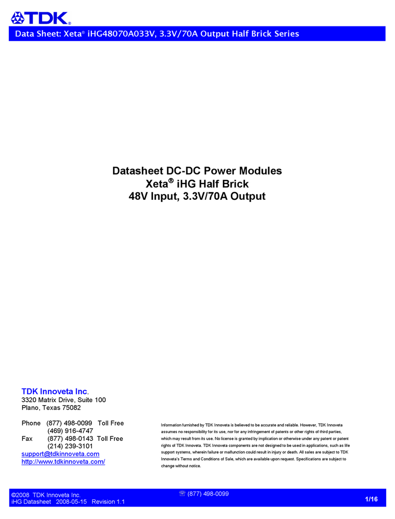
  9. TDK Belleta iEA Series User manual

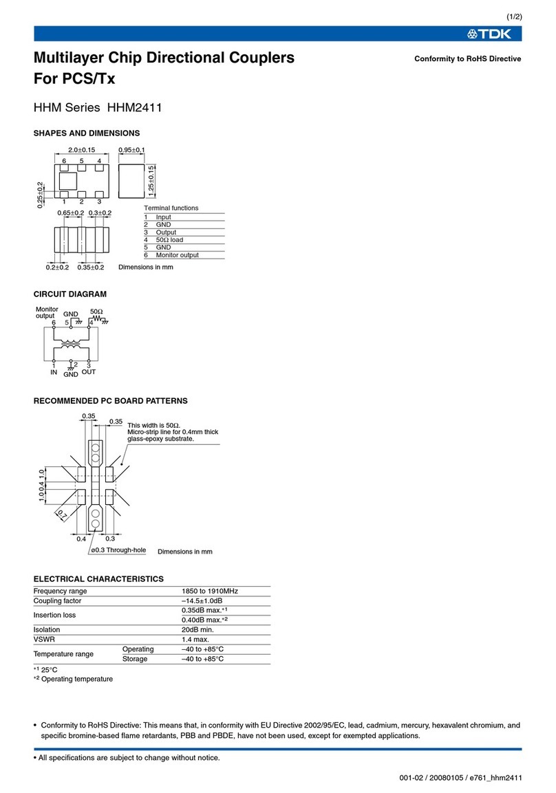
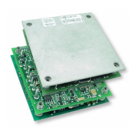
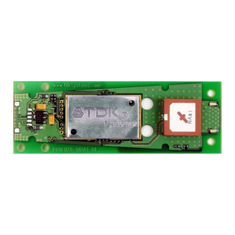
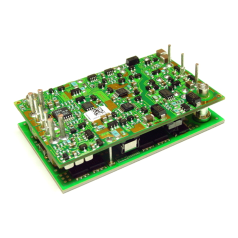
TDK Belleta iEA Series User manual

Data Sheet: Belleta
®
iEA Series –Single Output Eighth Brick
©2004 TDK Innoveta® Inc.
iEAFullDatasheet 032707 3/29/2007 Revision 2.0
℡
877) 498
-
0099
1/41
Belleta® iEA Series DC/DC Power Modules
48V Input, 25A Output
Eighth Brick
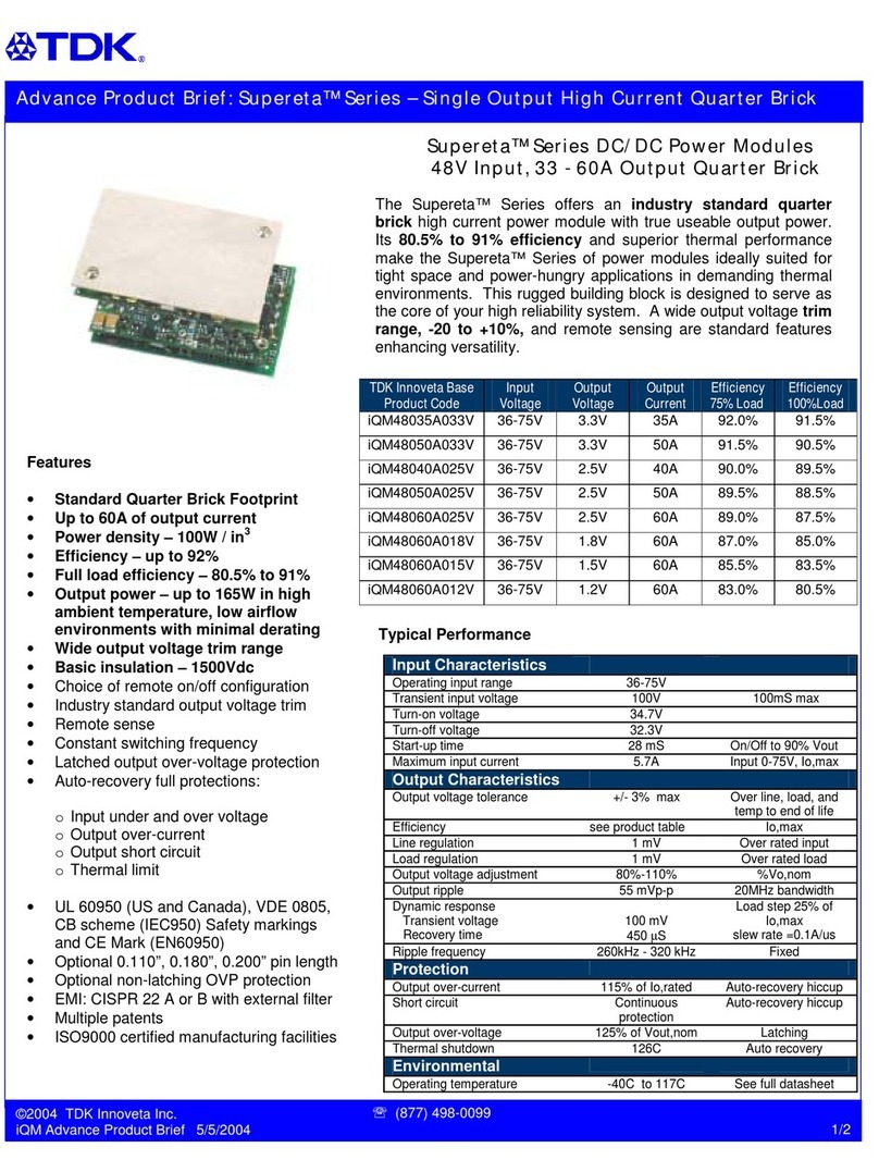
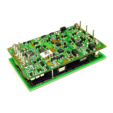
The Belleta Series offers an industry standard
eighth brick power module with true useable
power. Thanks to its low component count and
single-board open-frame design, it provides both
better electrical and thermal performance, and
lower cost than many other suppliers’ eighth brick
product offerings. Belleta® modules are perfect
for both next generation planning and cost
reduction design environments
Standard Features:
• Size – 58.4mm x 22.9 mm x 8.8
mm 2.3 in. x 0.9 in. x 0.347 in.)
• Thru-hole pins 3.68 mm 0.145”)
• High efficiency – greater than 89%
• 1500Vdc isolation voltage
• Meets basic insulation spacing
requirements
• Constant switching frequency
• Industry Standard Footprint
• Output Voltage Adjustment
• Remote on/off positive logic)
• Remote sense
• Auto-recovering output over-
voltage protection
• Auto-recovering output over-
current protection
• Auto-recovering output short circuit
protection
• Auto-recovering over-temperature
protection
• UL 60950 US and Canada), VDE
0805, CB scheme IEC950), CE
Mark EN60950)
• ISO Certified manufacturing
facilities
• Patented Design
Optional Features:
• Remote on/off negative logic)
• Latching output over-voltage
protection
• Short Thru-hole pins 2.79 mm
0.110”)
• Long Thru-hole pins 5.08 mm
0.200”)
Data Sheet: Belleta
®
iEA Series –Single Output Eighth Brick
©2004 TDK Innoveta® Inc.
iEAFullDatasheet 032707 3/29/2007 Revision 2.0
℡
877) 498
-
0099
2/41
Ordering information:
Product
Identifier
Package
Size Platform Input
Voltage
Output
Current/
Po er
Output
Units
Main
Output
Voltage
# of
Outputs Safety
Class Feature Set
i E A 48 020 A 033 V -
0 00
TDK Innoveta Eighth-
brick Belleta 36-75V
015 –15A
020 – 20A
025 – 25A
Amps
120 – 12V
050 – 5V
033 – 3.3V
025 – 2.5V
018 – 1.8V
015 – 1.5V
012 – 1.2V
Single 00 – Standard
Option Table:
Feature
Set
Positive Logic
On/Off
Negative Logic
On/Off
0.110” Pin
Length
0.200” Pin
Length
0.145” Pin
Length
Latching
OVP
00 X X
01 X X
02 X X
03 X X
04 X X
05 X X
11 X X X
15 X X X
Product Offering:
Code Input Voltage Output Voltage Output
Current
Maximum
Output Po er Efficiency
iEA48007A120V 36-75V 12V 6.5A 78W 91%
iEA48015A050V 36-75V 5V 15A 75W 90%
iEA48020A033V 36-75V 3.3V 20A 66W 90%
iEA48025A025V 36-75V 2.5V 25A 62.5W 86%
iEA48025A018V 36-75V 1.8V 25A 45W 83%
iEA48025A015V 36-75V 1.5V 25A 37.5W 81%
iEA48025A012V 36-75V 1.2V 25A 30W 78%
3320 Matrix Drive, Suite 100
Richardson, TX 75082
Phone 877) 498-0099 Toll Free
469) 916-4747
Fax 877) 498-0143 Toll Free
214) 239-3101
support@tdkinnoveta.com
http://www.tdkinnoveta.com/
Data Sheet: Belleta
®
iEA Series –Single Output Eighth Brick
©2004 TDK Innoveta® Inc.
iEAFullDatasheet 032707 3/29/2007 Revision 2.0
℡
877) 498
-
0099
3/41
Mechanical Specification:
Dimensions are in mm [in]. Unless otherwise specified tolerances are: x.x ± 0.5 [0.02], x.xx and x.xxx ± 0.25 [0.010].
1.02 [0.040] DIA Pin
2.03 [0.080] DIA Stand-Offs
6 Pins
1.57 [0.062] DIA Pin
2.59 [0.102] DIA Stand-Offs
2 Pins
Recommended Hole Pattern: top view)
1
2
3
8
7
6
5
4
Pin Assignment:
PIN FUNCTION PIN FUNCTION
1 Vin +) 4 Vo -)
2 On/Off 5 Sense -)
3 Vin -) 6 Trim
7 Sense +)
8 Vo +)
Pin base material is brass with tin plating; the maximum module weight is 30.4g 1.07 oz).
Data Sheet: Belleta
®
iEA Series –Single Output Eighth Brick
©2004 TDK Innoveta® Inc.
iEAFullDatasheet 032707 3/29/2007 Revision 2.0
℡
877) 498
-
0099
4/41
Absolute Maximum Ratings:
Stress in excess of Absolute Maximum Ratings may cause permanent damage to the device.
Input Characteristics:
Unless otherwise specified, specifications apply over all Rated Input Voltage, Resistive Load, and Temperature conditions.
Characteristic Min Typ Max Unit Notes & Conditions
Operating Input Voltage 36 48 75 Vdc
Maximum Input Current --- --- 4 A Vin = 0 to Vin,max
Turn-on Voltage --- 33 --- Vdc
Turn-off Voltage 26 30 --- Vdc
Hysteresis 0.5 3 --- Vdc
Startup Delay Time from application of input
voltage
--- 35 --- mS Vo = 0 to 0.1*Vo,nom; on/off =on,
Io=Io,max, Tc=25˚C
Startup Delay Time from on/off --- 35 --- mS Vo = 0 to 0.1*Vo,nom; Vin = Vi,nom,
Io=Io,max,Tc=25˚C
Output Voltage Rise Time --- 50 --- mS Io=Io,max,Tc=25˚C, Vo=0.1 to 0.9*Vo,nom
Inrush Transient --- --- 0.2 A
2
s
Input Reflected Ripple --- 15 --- mApp See input/output ripple and noise
measurements figure; BW = 20 MHz
Input Ripple Rejection --- 55 --- dB @120Hz
Caution: The power modules are not internally fused. An external input line normal blow fuse with a
maximum value of 10A is required, see the Safety Considerations section of the data sheet.
Characteristic Min Max Unit Notes & Conditions
Continuous Input Voltage -0.5 80 Vdc
Transient Input Voltage --- 100 Vdc 100mS max.
Isolation Voltage --- 1500 Vdc
Storage Temperature -55 125 ˚C
Operating Temperature Range Tc)
-40 125 ˚C
Measured at the location specified in the thermal
measurement figure. Maximum temperature varies
with model number, output current, and module
orientation – see curve in thermal performance
section of the data sheet.
Data Sheet: Belleta
®
iEA Series –Single Output Eighth Brick
©2004 TDK Innoveta® Inc.
iEAFullDatasheet 032707 3/29/2007 Revision 2.0
℡
877) 498
-
0099
5/41
Electrical Data:
iEA48007A120V-000 through -015: 12V, 6.5A Output
Characteristic Min Typ Max Unit Notes & Conditions
Output Voltage Initial Setpoint 11.64 12 12.36 Vdc Vin=Vin,nom; Io=Io,max; Tc = 25˚C
Output Voltage Tolerance 11.58 12 12.42 Vdc Over all rated input voltage, load, and
temperature conditions to end of life
Efficiency --- 90.5 --- % Vin=Vin,nom; Io=Io,max; Tc = 25˚C
Line Regulation --- 10 24 mV Vin=Vin,min to Vin,max
Load Regulation --- 10 24 mV Io=Io,min to Io,max
Temperature Regulation --- 60 240 mV Tc=Tc,min to Tc,max
Output Current 0.5 --- 6.5 A
At loads less than Io,min the module will
continue to regulate the output voltage, but
the output ripple may increase
Output Current Limiting Threshold --- 8.5 --- A Vo = 0.9*Vo,nom, Tc<Tc,max
Short Circuit Current --- 12 --- A Vo = 0.25V, Tc = 25˚C
--- 80 200 mVpp
Output Ripple and Noise Voltage
--- 26 --- mVrms
Measured across one 1.0 uF ceramic
capacitor and a 10uF tantalum capacitor –
see input/output ripple measurement figure;
BW = 20MHz
Output Voltage Adjustment Range 90 --- 110 %Vo,nom
Output Voltage Sense Range --- --- 10 %Vo,nom
Dynamic Response:
Recovery Time
Transient Voltage
---
---
60
220
---
---
uS
mV
di/dt = 0.1A/uS, Vin=Vin,nom; load step
from 50% to 75% of Io,max
Output Voltage Overshoot during startup --- --- 5 % Vin=Vin,nom; Io=Io,max,Tc=25˚C
Switching Frequency --- 400 --- kHz Fixed
Output Over Voltage Protection 13.6 --- 15.7 V
External Load Capacitance 0 --- 2000& uF
Isolation Capacitance --- 1000 --- pF
Isolation Resistance 10 --- --- MΩ
Vref 1.225 V Required for trim calculation
& Contact TDK Innoveta for applications that require additional capacitance or very low esr
Data Sheet: Belleta
®
iEA Series –Single Output Eighth Brick
©2004 TDK Innoveta® Inc.
iEAFullDatasheet 032707 3/29/2007 Revision 2.0
℡
877) 498
-
0099
6/41
Electrical Characteristics:
iEA48007A120V-000 through -015: 12V, 6.5A Output
iEA48007A120V-000 Typical Efficiency vs. Input
Voltage at Ta=25 degrees.
iEA48007A120V-000 Typical Power Dissipation vs.
Input Voltage at Ta=25 degrees
iEA48007A120V-000 Typical Efficiency vs. Input
Voltage at Ta=85 degrees.
iEA48007A120V-000 Typical Power Dissipation vs.
Input Voltage at Ta=85 degrees
70
75
80
85
90
95
0 0.7 1.4 2.1 2.8 3.5 4.2 4.9 5.6 6.3 7
Output Current (A)
Efficiency, η
η
η
η(%)
Vin = 36V Vin = 48V Vin = 75V
0
2
4
6
8
10
12
0 0.7 1.4 2.1 2.8 3.5 4.2 4.9 5.6 6.3 7
Output Current (A)
Po er Dissipation (W)
Vin = 36V Vin = 48V Vin = 75V
70
75
80
85
90
95
0 0.7 1.4 2.1 2.8 3.5 4.2 4.9 5.6 6.3 7
Output Current (A)
Efficiency, η
η
η
η(%)
Vin = 36V Vin = 48V Vin = 75V
0
2
4
6
8
10
12
14
0 0.7 1.4 2.1 2.8 3.5 4.2 4.9 5.6 6.3 7
Output Current (A)
Po er Dissipation (W)
Vin = 36V Vin = 48V Vin = 75V
Data Sheet: Belleta
®
iEA Series –Single Output Eighth Brick
©2004 TDK Innoveta® Inc.
iEAFullDatasheet 032707 3/29/2007 Revision 2.0
℡
877) 498
-
0099
7/41
Electrical Characteristics (continued):
iEA48007A120V-000 through -015: 12V, 6.5A Output
iEA48007A120V-000 Typical Output Voltage vs. Load
Current at Ta = 25 degrees
iEA48007A120V-001 Typical startup characteristic from
on/off at full load. Ch 1 - on/off signal, Ch 2 – output
voltage
iEA48007A120V-000 Typical Output voltage response
to load step from 50% to 75% of full load with output
current slew rate of 0.1A/uS.
iEA48007A120V-000 Typical Output voltage response
to load step from 50% to 75% of full load with output
current slew rate of 0.1A/uS and 2200uF external load.
%
Change
of Vout
Trim
Down
Resistor
Kohm)
%
Change
of Vout
Trim Up
Resistor
Kohm)
-5% 91.8K +5% 937K
-10% 40.8K +10% 488K
e.g. trim up 5%
Rup 5.1 12×100 5+( )⋅
1.225
5
×
510
5
−10.2−






K⋅:=
iEA48007A120V-000 Calculated resistor values for
output voltage adjustment
11.64
11.74
11.84
11.94
12.04
12.14
12.24
12.34
0 0.7 1.4 2.1 2.8 3.5 4.2 4.9 5.6 6.3 7
Output Current (A)
Output Voltage (V)
Vin = 36V Vin = 48V Vin = 75V
Data Sheet: Belleta
®
iEA Series –Single Output Eighth Brick
©2004 TDK Innoveta® Inc.
iEAFullDatasheet 032707 3/29/2007 Revision 2.0
℡
877) 498
-
0099
8/41
Electrical Characteristics (continued):
iEA48007A120V-000 through -015: 12V, 6.5A Output
iEA48007A120V-000 Typical Output Current Limit
Characteristics vs. Input Voltage at Ta=25 degrees.
iEA48007A120V-000 Typical Output Ripple at nominal
input voltage and full load at Ta=25 degrees
iEA48007A120V-000 Typical Input Current vs. Input
Voltage Characteristics
iEA48007A120V-000 Typical Output Voltage vs. Input
Voltage Characteristics
0
2
4
6
8
10
12
14
27 32 37 41 46 51 56 61 65 70 75
Input Voltage (V)
Output Voltage (V)
Io_min = 0A Io_mid = 3.3A Io_max = 6.5A
0
0.5
1
1.5
2
2.5
3
3.5
27 32 37 41 46 51 56 61 65 70 75
Input Voltage (V)
Input Current (A)
Io_min = 0A Io_mid = 3.3A Io_max = 6.5A
10
10.5
11
11.5
12
12.5
0 2 4 6 8 10 12
Output Current (A)
Output Voltage (V)
Vin = 36V Vin = 48V Vin = 75V
Data Sheet: Belleta
®
iEA Series –Single Output Eighth Brick
©2004 TDK Innoveta® Inc.
iEAFullDatasheet 032707 3/29/2007 Revision 2.0
℡
877) 498
-
0099
9/41
Thermal Performance:
iEA48007A120V-000 through -015: 12V, 6.5A Output
iEA48007A120V-000 maximum output current vs. ambient
temperature at nominal input voltage for airflow rates natural
convection 60lfm) to 600lfm with airflow from pin 3 to pin 1.
iEA48007A120V-000 maximum output current vs.ambient
temperature at nominal input voltage for airflow rates natural
convection 60lfm) to 600lfm with airflow from pin 1 to pin 3.
iEA48007A120V-000 thermal measurement location –
top view
Both the thermal curves provided and the example given above are based upon measurements made in TDK Innoveta’s
experimental test setup that is described in the Thermal Management section. Due to the large number of variables in
system design, TDK Innoveta recommends that the user verify the module’s thermal performance in the end application.
The critical component should be thermo coupled and monitored, and should not exceed the temperature limit specified in
the derating curve above. It is critical that the thermocouple be mounted in a manner that gives direct thermal contact or
significant measurement errors may result. TDK Innoveta can provide modules with a thermocouple pre-mounted to the
critical component for system verification tests.
Thermal measurement
location on PWB Cu
Best orientation
airflo
0
1
2
3
4
5
6
7
25 45 65 85 105 125
T emp er at ur e ( o C )
NC
0.5 m/ s 100 LFM)
1.0 m/ s 200 LFM)
2.0 m/ s 400 LFM)
3.0 m/ s 600 LFM)
Tc, Thermal Limit
0
1
2
3
4
5
6
7
25 45 65 85 105 125
Temperature (oC)
Output Current (A)
NC
0.5 m/s 100 LFM)
1.0 m/s 200 LFM)
2.0 m/s 400 LFM)
3.0 m/s 600 LFM)
Tc, Thermal Limit
Data Sheet: Belleta
®
iEA Series –Single Output Eighth Brick
©2004 TDK Innoveta® Inc.
iEAFullDatasheet 032707 3/29/2007 Revision 2.0
℡
877) 498
-
0099
10/41
Electrical Data:
iEA48015A050V-000 through -015: 5V, 15A Output
Characteristic Min Typ Max Unit Notes & Conditions
Output Voltage Initial Setpoint 4.92 5 5.08 Vdc Vin=Vin,nom; Io=Io,max; Tc = 25˚C
Output Voltage Tolerance 4.85 5 5.15 Vdc Over all rated input voltage, load, and
temperature conditions to end of life
Efficiency --- 90 --- % Vin=Vin,nom; Io=Io,max; Tc = 25˚C
Line Regulation --- 2 10 mV Vin=Vin,min to Vin,max
Load Regulation --- 1 10 mV Io=Io,min to Io,max
Temperature Regulation --- 30 75 mV Tc=Tc,min to Tc,max
Output Current 1 --- 15 A
At loads less than Io,min the module will
continue to regulate the output voltage, but
the output ripple may increase
Output Current Limiting Threshold --- 20 --- A Vo = 0.9*Vo,nom, Tc<Tc,max
Short Circuit Current --- 14 --- A Vo = 0.25V, Tc = 25˚C
--- 55 125 mVpp
Output Ripple and Noise Voltage
--- 7 --- mVrms
Measured across one 0.1 uF ceramic
capacitor and a 22uF ceramic capacitor –
see input/output ripple measurement figure;
BW = 20MHz
Output Voltage Adjustment Range 90 --- 110 %Vo,nom
Output Voltage Sense Range --- --- 10 %Vo,nom
Dynamic Response:
Recovery Time
Transient Voltage
---
---
100
200
---
---
uS
mV
di/dt = 0.1A/uS, Vin=Vin,nom; load step
from 50% to 75% of Io,max
Output Voltage Overshoot during startup --- --- 250 mV Vin=Vin,nom; Io=Io,max,Tc=25˚C
Switching Frequency --- 400 --- kHz Fixed
Output Over Voltage Protection 5.7 --- 6.7 V
External Load Capacitance 0 --- 5000& uF
Isolation Capacitance --- 1000 --- pF
Isolation Resistance 10 --- --- MΩ
Vref 1.225 V Required for trim calculation
& Contact TDK Innoveta for applications that require additional capacitance or very low esr
Data Sheet: Belleta
®
iEA Series –Single Output Eighth Brick
©2004 TDK Innoveta® Inc.
iEAFullDatasheet 032707 3/29/2007 Revision 2.0
℡
877) 498
-
0099
11/41
Electrical Characteristics:
iEA48015A050V-000 through -015: 5V, 15A Output
iEA48015A050V-000 Typical Efficiency vs. Input
Voltage at Ta=25 degrees.
iEA48015A050V-000 Typical Power Dissipation vs.
Input Voltage at Ta=25 degrees
iEA48015A050V-000 Typical Efficiency vs. Input
Voltage at Ta=85 degrees.
iEA48015A050V-000 Typical Power Dissipation vs.
Input Voltage at Ta=85 degrees
70
75
80
85
90
95
1 2.4 3.8 5.2 6.6 8 9.4 10.8 12.2 13.6 15
Output Current (A)
Efficiency, η
η
η
η(%)
Vin = 36V Vin = 48V Vin = 75V
0
2
4
6
8
10
12
1 2.4 3.8 5.2 6.6 8 9.4 10.8 12.2 13.6 15
Output Current (A)
Po er Dissipation (W)
Vin = 36V Vin = 48V Vin = 75V
70
75
80
85
90
95
1 2.4 3.8 5.2 6.6 8 9.4 10.8 12.2 13.6 15
Output Current (A)
Efficiency, η
η
η
η(%)
Vin = 36V Vin = 48V Vin = 75V
0
2
4
6
8
10
12
1 2.4 3.8 5.2 6.6 8 9.4 10.8 12.2 13.6 15
Output Current (A)
Po er Dissipation (W)
Vin = 36V Vin = 48V Vin = 75V
Data Sheet: Belleta
®
iEA Series –Single Output Eighth Brick
©2004 TDK Innoveta® Inc.
iEAFullDatasheet 032707 3/29/2007 Revision 2.0
℡
877) 498
-
0099
12/41
Electrical Characteristics (continued):
iEA48015A050V-000 through -015: 5V, 15A Output
iEA48015A050V-000 Typical Output Voltage vs. Load
Current at Ta = 25 degrees
iEA48015A050V-001 Typical startup characteristic from
on/off at full load. Ch4 - on/off signal, Ch 1 – output
voltage
iEA48015A050V-000 Typical Output voltage response
to load step from 50% to 75% of full load with output
current slew rate of 0.1A/uS.
iEA48015A050V-000 Typical Output voltage response
to load step from 50% to 75% of full load with output
current slew rate of 0.1A/uS and 5000uF load.
%
Change
of Vout
Trim
Down
Resistor
Kohm)
%
Change
of Vout
Trim Up
Resistor
Kohm)
-5% 91.8K +5% 325K
-10% 40.8K +10% 168K
e.g. trim up 5%
Rup 5.1 5×100 5+( )⋅
1.225
5
×
510
5
−10.2−






K⋅:=
iEA48015A050V-000 Calculated resistor values for
output voltage adjustment
4.95
4.96
4.97
4.98
4.99
5
5.01
5.02
5.03
5.04
5.05
1 2.4 3.8 5.2 6.6 8 9.4 10.8 12.2 13.6 15
Output Current (A)
Output Voltage (V)
Vin = 36V Vin = 48V Vin = 75V
Data Sheet: Belleta
®
iEA Series –Single Output Eighth Brick
©2004 TDK Innoveta® Inc.
iEAFullDatasheet 032707 3/29/2007 Revision 2.0
℡
877) 498
-
0099
13/41
Electrical Characteristics (continued):
iEA48015A050V-000 through -015: 5V, 15A Output
iEA48015A050V-000 Typical Output Current Limit
Characteristics vs. Input Voltage at Ta=25 degrees.
iEA48015A050V-000 Typical Output Ripple at nominal
input voltage and full load at Ta=25 degrees
iEA48015A050V-000 Typical Input Current vs. Input
Voltage Characteristics
iEA48015A050V-000 Typical Output Voltage vs. Input
Voltage Characteristics
4.85
4.87
4.89
4.91
4.93
4.95
4.97
4.99
5.01
1 6 11 16 21 26
Output Current (A)
Output Voltage (V)
Vin = 36V Vin = 48V Vin = 75V
0
0.5
1
1.5
2
2.5
3
27 32 37 41 46 51 56 61 65 70 75
Input Voltage (V)
Input Current (A)
Io_min = 0.8A Io_mid = 7.5A Io_max = 15.1A
0
1
2
3
4
5
6
27 32 37 41 46 51 56 61 65 70 75
Input Voltage (V)
Output Voltage (V)
Io_min = 0.8A Io_mid = 7.5A Io_max = 15.1A
Data Sheet: Belleta
®
iEA Series –Single Output Eighth Brick
©2004 TDK Innoveta® Inc.
iEAFullDatasheet 032707 3/29/2007 Revision 2.0
℡
877) 498
-
0099
14/41
Thermal Performance:
iEA48015A050V-000 through -015: 5V, 15A Output
iEA48015A050V-000 maximum output current vs. ambient
temperature at nominal input voltage for airflow rates natural
convection 60lfm) to 600lfm with airflow from pin 3 to pin 1.
iEA48015A050V-000 thermal measurement location –
top view
Both the thermal curves provided and the example given above are based upon measurements made in TDK Innoveta’s
experimental test setup that is described in the Thermal Management section. Due to the large number of variables in
system design, TDK Innoveta recommends that the user verify the module’s thermal performance in the end application.
The critical component should be thermo coupled and monitored, and should not exceed the temperature limit specified in
the derating curve above. It is critical that the thermocouple be mounted in a manner that gives direct thermal contact or
significant measurement errors may result. TDK Innoveta can provide modules with a thermocouple pre-mounted to the
critical component for system verification tests.
Thermal measurement
location on PWB Cu
Best orientation
airflo
0
2
4
6
8
10
12
14
16
25 45 65 85 105 125
Temperature (oC)
Output Current (A)
NC
0.5 m/s 100 LFM)
1.0 m/s 200 LFM)
2.0 m/s 400 LFM)
3.0 m/s 600 LFM)
Tc, Thermal Limit
Data Sheet: Belleta
®
iEA Series –Single Output Eighth Brick
©2004 TDK Innoveta® Inc.
iEAFullDatasheet 032707 3/29/2007 Revision 2.0
℡
877) 498
-
0099
15/41
Electrical Data:
iEA48020A033V-000 through -015: 3.3V, 20A Output
Characteristic Min Typ Max Unit Notes & Conditions
Output Voltage Initial Setpoint 3.25 3.3 3.35 Vdc Vin=Vin,nom; Io=Io,max; Tc = 25˚C
Output Voltage Tolerance 3.20 3.3 3.40 Vdc Over all rated input voltage, load, and
temperature conditions to end of life
Efficiency --- 89.5 --- % Vin=Vin,nom; Io=Io,max; Tc = 25˚C
Line Regulation --- 2 7 mV Vin=Vin,min to Vin,max
Load Regulation --- 3 8 mV Io=Io,min to Io,max
Temperature Regulation --- 15 60 mV Tc=Tc,min to Tc,max
Output Current 1.5 --- 20 A
At loads less than Io,min the module will
continue to regulate the output voltage, but
the output ripple may increase
Output Current Limiting Threshold --- 29 --- A Vo = 0.9*Vo,nom, Tc<Tc,max
Short Circuit Current --- 20 --- A Vo = 0.25V, Tc = 25˚C
--- 35 100 mVpp
Output Ripple and Noise Voltage
--- 11 --- mVrms
Measured across one 1.0 uF ceramic
capacitor and a 10uF tantalum capacitor –
see input/output ripple measurement figure;
BW = 20MHz
Output Voltage Adjustment Range 90 --- 110 %Vo,nom The trim range is reduced to 105% when
the input voltage is below 40V.
Output Voltage Sense Range --- --- 10 %Vo,nom The sense range is reduced to 5% when the
input voltage is below 40V.
Dynamic Response:
Recovery Time
Transient Voltage
---
---
90
180
---
---
uS
mV
di/dt = 0.1A/uS, Vin=Vin,nom; load step
from 50% to 75% of Io,max
Output Voltage Overshoot during startup --- --- 165 mV Vin=Vin,nom; Io=Io,max,Tc=25˚C
Switching Frequency --- 400 --- kHz Fixed
Output Over Voltage Protection 3.75 --- 4.4 V
External Load Capacitance 100 --- 5000& uF Recommend TDK part C3225X5R0J107MT
Isolation Capacitance --- 1000 --- pF
Isolation Resistance 10 --- --- MΩ
Vref 1.225 V Required for trim calculation
& Contact TDK Innoveta for applications that require additional capacitance or very low esr
Data Sheet: Belleta
®
iEA Series –Single Output Eighth Brick
©2004 TDK Innoveta® Inc.
iEAFullDatasheet 032707 3/29/2007 Revision 2.0
℡
877) 498
-
0099
16/41
Electrical Characteristics:
iEA48020A033V-000 through -015: 3.3V, 20A Output
iEA48020A033V-000 Typical Efficiency vs. Input
Voltage at Ta=25 degrees.
iEA48020A033V-000 Typical Power Dissipation vs.
Input Voltage at Ta=25 degrees
iEA48020A033V-000 Typical Efficiency vs. Input
Voltage at Ta=85 degrees.
iEA48020A033V-000 Typical Power Dissipation vs.
Input Voltage at Ta=85 degrees
70
75
80
85
90
95
1 2.9 4.8 6.7 8.6 10.5 12.4 14.3 16.2 18.1 20
Output Current (A)
Efficiency, η
η
η
η(%)
Vin = 36V Vin = 48V Vin = 75V
0
2
4
6
8
10
12
1 2.9 4.8 6.7 8.6 10.5 12.4 14.3 16.2 18.1 20
Output Current (A)
Po er Dissipation (W)
Vin = 36V Vin = 48V Vin = 75V
70
75
80
85
90
95
1 2.9 4.8 6.7 8.6 10.5 12.4 14.3 16.2 18.1 20
Output Current (A)
Efficiency, η
η
η
η(%)
Vin = 36V Vin = 48V Vin = 75V
0
2
4
6
8
10
12
1 2.9 4.8 6.7 8.6 10.5 12.4 14.3 16.2 18.1 20
Output Current (A)
Po er Dissipation (W)
Vin = 36V Vin = 48V Vin = 75V
Data Sheet: Belleta
®
iEA Series –Single Output Eighth Brick
©2004 TDK Innoveta® Inc.
iEAFullDatasheet 032707 3/29/2007 Revision 2.0
℡
877) 498
-
0099
17/41
Electrical Characteristics (continued):
iEA48020A033V-000 through -015: 3.3V, 20A Output
iEA48020A033V-000 Typical Output Voltage vs. Load
Current at Ta = 25 degrees
iEA48020A033V-001 Typical startup characteristic from
on/off at full load. Ch2 - on/off signal, Ch 1 – output
voltage
iEA48020A033V-000 Typical output voltage response
to load step from 50% to 75% of full load with output
current slew rate of 0.1A/uS.
iEA48020A033V-000 Typical output voltage response
to load step from 50% to 75% of full load with output
current slew rate of 0.1A/uS and 5000uF load.
%
Change
of Vout
Trim
Down
Resistor
Kohm)
%
Change
of Vout
Trim Up
Resistor
Kohm)
-5% 91.8K +5% 176.3K
-10% 40.8K +10% 89.9K
e.g. trim up 5%
Rup 5.1 3.3×100 5+( )⋅
1.225
5
×
510
5
−10.2−






K⋅:=
iEA48020A033V-000 Calculated resistor values for
output voltage adjustment
3.25
3.27
3.29
3.31
3.33
3.35
1 2.9 4.8 6.7 8.6 10.5 12.4 14.3 16.2 18.1 20
Output Current (A)
Output Voltage (V)
Vin = 36V Vin = 48V Vin = 75V
Data Sheet: Belleta
®
iEA Series –Single Output Eighth Brick
©2004 TDK Innoveta® Inc.
iEAFullDatasheet 032707 3/29/2007 Revision 2.0
℡
877) 498
-
0099
18/41
Electrical Characteristics (continued):
iEA48020A033V-000 through -015: 3.3V, 20A Output
iEA48020A033V-000 Typical Output Current Limit
Characteristics vs. Input Voltage at Ta=25 degrees.
iEA48020A033V-000 Typical Output Ripple at nominal
input voltage and full load at Ta=25 degrees
iEA48020A033V-000 Typical Input Current vs. Input
Voltage Characteristics
iEA48020A033V-000 Typical Output Voltage vs. Input
Voltage Characteristics
0
0.5
1
1.5
2
2.5
3
27 32 37 41 46 51 56 61 65 70 75
Input Voltage (V)
Input Current (A)
Io_min = 1A Io_mid = 10A Io_max = 20A
0
0.5
1
1.5
2
2.5
3
3.5
27 32 37 41 46 51 56 61 65 70 75
Input Voltage (V)
Output Voltage (V)
Io_min = 1A Io_mid = 10A Io_max = 20A
3.25
3.26
3.27
3.28
3.29
3.3
3.31
3.32
20 22 24 26 28 30 32
Output Current (A)
Output Voltage (V)
Vin = 36V Vin = 48V Vin = 75V
Data Sheet: Belleta
®
iEA Series –Single Output Eighth Brick
©2004 TDK Innoveta® Inc.
iEAFullDatasheet 032707 3/29/2007 Revision 2.0
℡
877) 498
-
0099
19/41
Thermal Performance:
iEA48020A033V-000 through -015: 3.3V, 20A Output
iEA48020A033V-000 maximum output current vs. ambient
temperature at nominal input voltage for airflow rates natural
convection 60lfm) to 600lfm with airflow from pin 3 to pin 1.
iEA48020A033V-000 maximum output current vs. ambient
temperature at nominal input voltage for airflow rates natural
convection 60lfm) to 600lfm with airflow from pin 1 to pin 3.
iEA48020A033V-000 thermal measurement location –
top view
Both the thermal curves provided and the example given above are based upon measurements made in TDK Innoveta’s
experimental test setup that is described in the Thermal Management section. Due to the large number of variables in
system design, TDK Innoveta recommends that the user verify the module’s thermal performance in the end application.
The critical component should be thermo coupled and monitored, and should not exceed the temperature limit specified in
the derating curve above. It is critical that the thermocouple be mounted in a manner that gives direct thermal contact or
significant measurement errors may result. TDK Innoveta can provide modules with a thermocouple pre-mounted to the
critical component for system verification tests.
Thermal measurement
location on PWB Cu
Best orientation
airflo
5
10
15
20
25
30 40 50 60 70 80 90 100 110 120 130
Temperature (C)
Output Current (A)
NC
0.5 m/s 100 LFM)
1.0 m/s 200 LFM)
2.0 m/s 400 LFM)
3.0 m/s 600 LFM)
Tc, Thermal Limit
5
10
15
20
25
30 40 50 60 70 80 90 100 110 120 130
Temperature (C)
Output Current (A)
NC
0.5 m/s 100 LFM)
1.0 m/s 200 LFM)
2.0 m/s 400 LFM)
3.0 m/s 600 LFM)
Tc, Thermal Limit
Data Sheet: Belleta
®
iEA Series –Single Output Eighth Brick
©2004 TDK Innoveta® Inc.
iEAFullDatasheet 032707 3/29/2007 Revision 2.0
℡
877) 498
-
0099
20/41
Electrical Data:
iEA48025A025V-000 through -015: 2.5V, 25A Output
Characteristic Min Typ Max Unit Notes & Conditions
Output Voltage Initial Setpoint 2.46 2.5 2.54 Vdc Vin=Vin,nom; Io=Io,max; Tc = 25˚C
Output Voltage Tolerance 2.42 2.5 2.58 Vdc Over all rated input voltage, load, and
temperature conditions to end of life
Efficiency --- 85.5 --- % Vin=Vin,nom; Io=Io,max; Tc = 25˚C
Line Regulation --- 1 5 mV Vin=Vin,min to Vin,max
Load Regulation --- 1 7 mV Io=Io,min to Io,max
Temperature Regulation --- 10 50 mV Tc=Tc,min to Tc,max
Output Current 2.0 --- 25 A
At loads less than Io,min the module will
continue to regulate the output voltage, but
the output ripple may increase
Output Current Limiting Threshold --- 31 --- A Vo = 0.9*Vo,nom, Tc<Tc,max
Short Circuit Current --- 20 --- A Vo = 0.25V, Tc = 25˚C
--- 35 100 mVpp
Output Ripple and Noise Voltage
--- 11 --- mVrms
Measured across one 1.0 uF ceramic
capacitor and a 10uF tantalum capacitor –
see input/output ripple measurement figure;
BW = 20MHz
Output Voltage Adjustment Range 90 --- 110 %Vo,nom
Output Voltage Sense Range --- --- 10 %Vo,nom
Dynamic Response:
Recovery Time
Transient Voltage
---
---
100*
200*
---
---
uS
mV
di/dt = 0.1A/uS, Vin=Vin,nom; load step
from 50% to 75% of Io,max
Output Voltage Overshoot during startup --- --- 165 mV Vin=Vin,nom; Io=Io,max,Tc=25˚C
Switching Frequency --- 400 --- kHz Fixed
Output Over Voltage Protection 2.7 --- 3.5 V
External Load Capacitance 0 --- 5000& uF
Isolation Capacitance --- 1000 --- pF
Isolation Resistance 10 --- --- MΩ
Vref 1.225 V Required for trim calculation
& Contact TDK Innoveta for applications that require additional capacitance or very low esr

This manual suits for next models

7

Other TDK Computer Hardware manuals

TDK HHM Series HHM1518A3 User manual

TDK

TDK HHM Series HHM1518A3 User manual

TDK DEA Series DEA252450BT-7012D1 User manual

TDK

TDK DEA Series DEA252450BT-7012D1 User manual

TDK DEA Series DEA255395BT-2065D2 User manual

TDK

TDK DEA Series DEA255395BT-2065D2 User manual

TDK Supereta Series DC/DC User manual

TDK

TDK Supereta Series DC/DC User manual

TDK Supereta iQN48006A350V User manual

TDK

TDK Supereta iQN48006A350V User manual

TDK FReta Series User manual

TDK

TDK FReta Series User manual

TDK HHM Series HHM2409 User manual

TDK

TDK HHM Series HHM2409 User manual

TDK DEA Series DEA201990LT-9003D1 User manual
TDK

TDK DEA Series DEA201990LT-9003D1 User manual

TDK Dualeta iQA Series User manual

TDK

TDK Dualeta iQA Series User manual

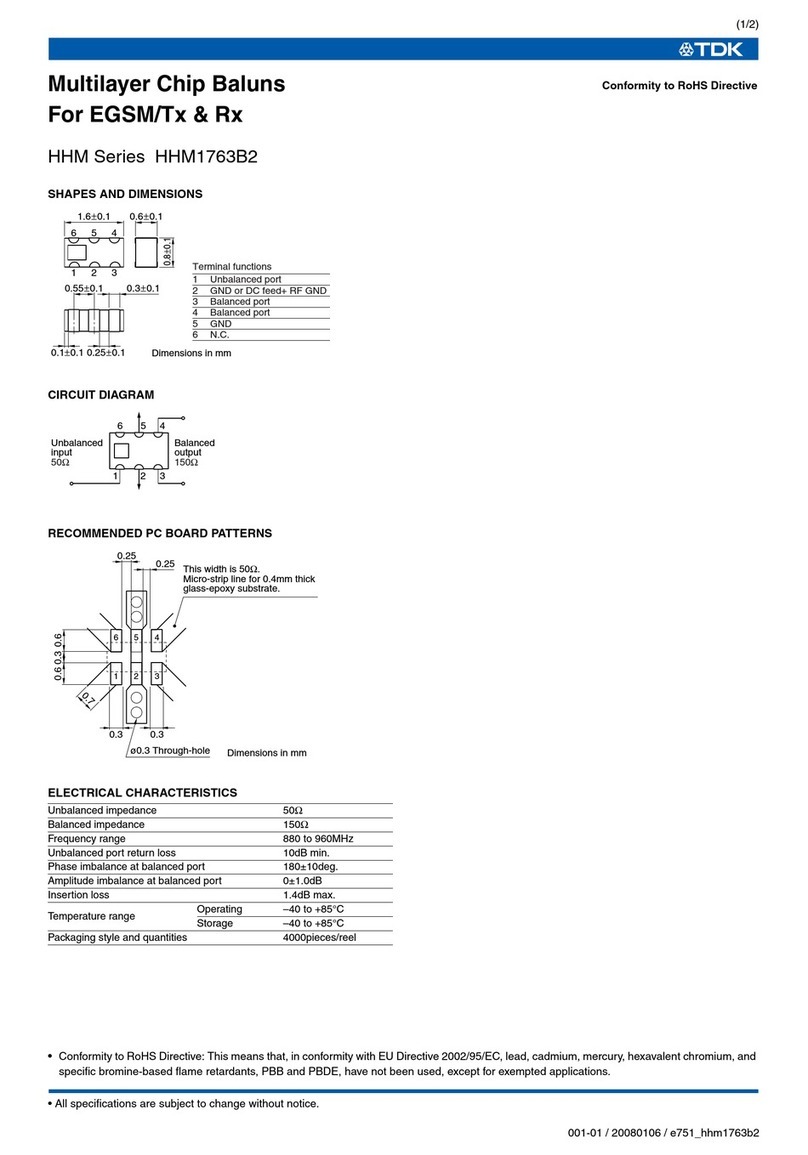
TDK HHM Series HHM1763B2 User manual

TDK

TDK HHM Series HHM1763B2 User manual

TDK AN-000300 Installation manual

TDK

TDK AN-000300 Installation manual

TDK DVB-H/ISDB-T User manual

TDK

TDK DVB-H/ISDB-T User manual

TDK HHM Series HHM1564A User manual

TDK

TDK HHM Series HHM1564A User manual

TDK DEA Series DEA202495BT-1242B2 User manual

TDK

TDK DEA Series DEA202495BT-1242B2 User manual

TDK HHM Series HHM2202SA1 User manual

TDK

TDK HHM Series HHM2202SA1 User manual

TDK J Series JBW User manual

TDK

TDK J Series JBW User manual

TDK WiMAX HHM Series HHM1715E1 User manual

TDK

TDK WiMAX HHM Series HHM1715E1 User manual

TDK EL Series EL0405 User manual

TDK

TDK EL Series EL0405 User manual

TDK DEA Series DEA165850LT-1197B2 User manual

TDK

TDK DEA Series DEA165850LT-1197B2 User manual

TDK HHM Series HHM1713E2 User manual

TDK

TDK HHM Series HHM1713E2 User manual
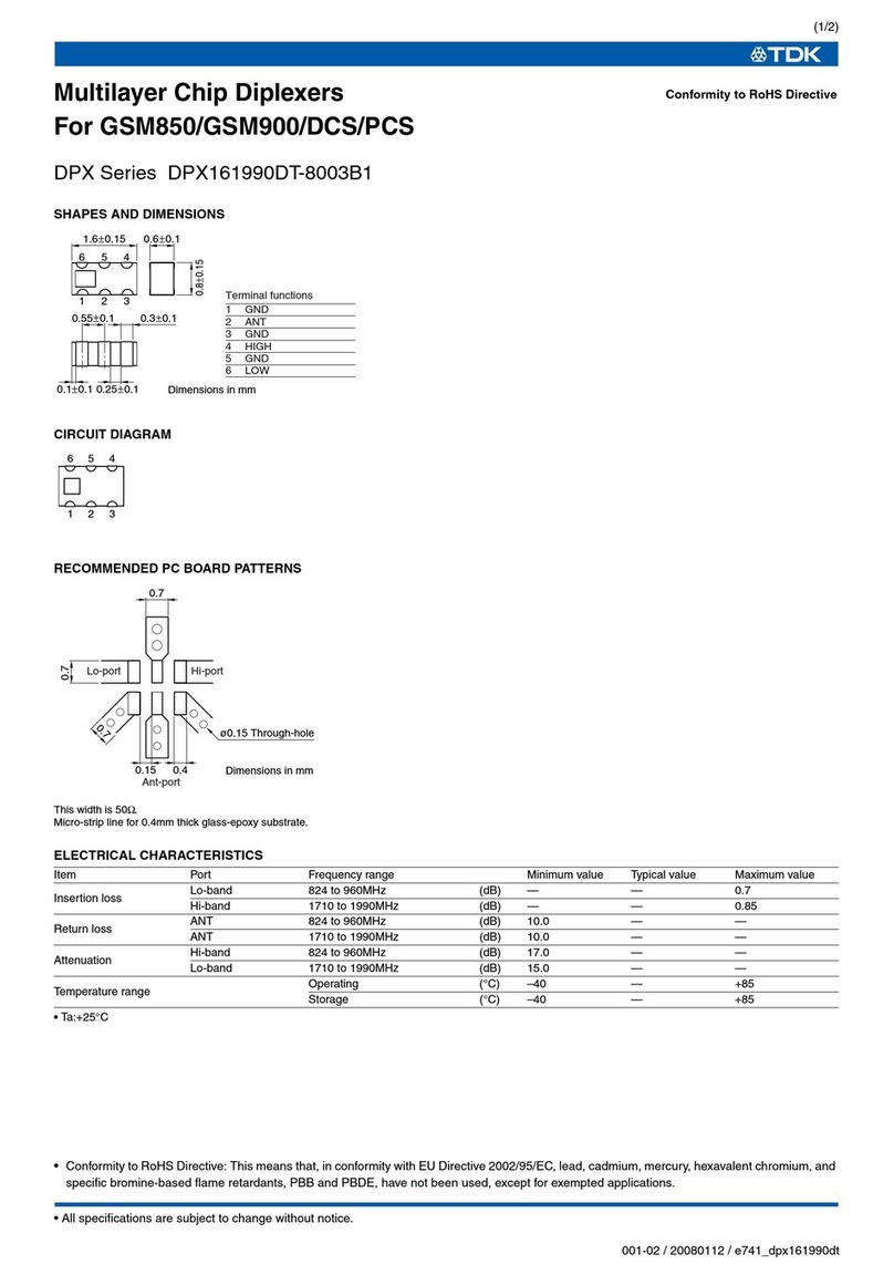
TDK DPX Series DPX161990DT-8003B1 User manual
TDK

TDK DPX Series DPX161990DT-8003B1 User manual

TDK CU Series User manual

TDK

TDK CU Series User manual

TDK VLCF Series VLCF4024-2 User manual

TDK

TDK VLCF Series VLCF4024-2 User manual

TDK DEA Series DEA162500LT-1217A1 User manual

TDK

TDK DEA Series DEA162500LT-1217A1 User manual

Popular Computer Hardware manuals by other brands

Nordic nPM1100 EK user guide

Nordic

Nordic nPM1100 EK user guide

StarTech.com 8STPEXM2SAT32N1 instruction manual

StarTech.com

StarTech.com 8STPEXM2SAT32N1 instruction manual

Stardom SOHOTANK MS2-TB3 user manual

Stardom

Stardom SOHOTANK MS2-TB3 user manual

Sonnet ENCORE/ST G4 DUET quick start guide

Sonnet

Sonnet ENCORE/ST G4 DUET quick start guide

Motorola DragonBall MC9328MX1 Reference manual

Motorola

Motorola DragonBall MC9328MX1 Reference manual

Renesas Emulation Probe M30850T-EPB user manual

Renesas

Renesas Emulation Probe M30850T-EPB user manual

VAF instruments 667 Instructions for installation, operation and maintenance

VAF instruments

VAF instruments 667 Instructions for installation, operation and maintenance

Manhattan MondoHub II instructions

Manhattan

Manhattan MondoHub II instructions

Toshiba PD750U-0001Q user guide

Toshiba

Toshiba PD750U-0001Q user guide

Crestron DIN Rail Control Processor DIN-AP2 Operations & installation guide

Crestron

Crestron DIN Rail Control Processor DIN-AP2 Operations & installation guide

Tektronix Colorado Data Systems 53A-334 operating manual

Tektronix

Tektronix Colorado Data Systems 53A-334 operating manual

Intel Agilex Series Configuration user guide

Intel

Intel Agilex Series Configuration user guide

C&T Solution VCO-6131E-4M2 user manual

C&T Solution

C&T Solution VCO-6131E-4M2 user manual

Peak PCAN-miniPCIe user manual

Peak

Peak PCAN-miniPCIe user manual

Freescale Semiconductor Motorola MMDS0508 Operation manual

Freescale Semiconductor

Freescale Semiconductor Motorola MMDS0508 Operation manual

Cypress Semiconductor Astoria DMB-T Reference Design Guide

Cypress Semiconductor

Cypress Semiconductor Astoria DMB-T Reference Design Guide

GE VMIVME-2533 Series Hardware reference

GE

GE VMIVME-2533 Series Hardware reference

Kontron microETXexpress-DC user guide

Kontron

Kontron microETXexpress-DC user guide

manuals.online logo
manuals.online logoBrands
  • About & Mission
  • Contact us
  • Privacy Policy
  • Terms and Conditions

Copyright 2025 Manuals.Online. All Rights Reserved.