manuals.online logo
Brands
  1. Home
  2. •
  3. Brands
  4. •
  5. TE Connectivity
  6. •
  7. Crimping Tools
  8. •
  9. TE Connectivity 234170-1 User manual

TE Connectivity 234170-1 User manual

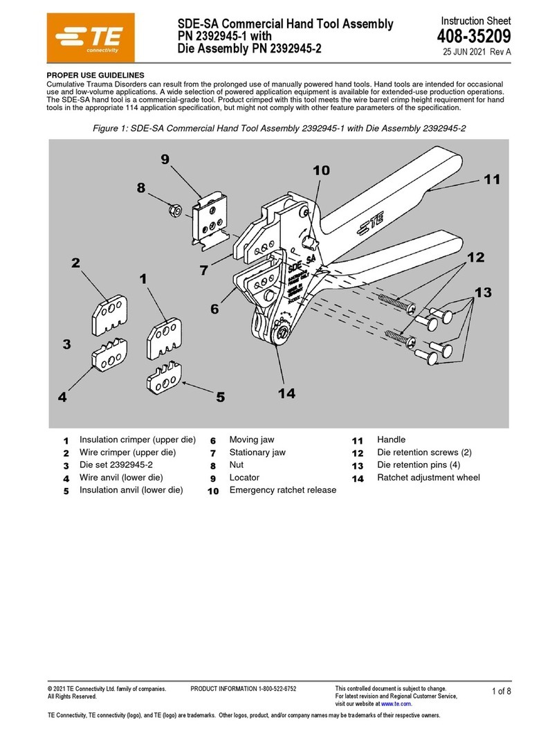
Instruction Sheet
取扱説明書
411
-
5712
19 NOV 2013 Rev D
Heavy head hand tool for dynamic contact.
D
-
5
(S)
ダイナミック D-5 (S)用 ヘビー・ヘッド手動工具
TOOL P/N: 234170-1
©2013 Tyco Electronics Japan G.K.,
a TE Connectivity Ltd. Company
All Rights Reserved
* Trademark
タイコエレクトロニクス ジャパン合同会社、TE Connectivity Ltd. グループ
1 of 4
TE logo is a trademark. Other products, logos, and company names might be trademarks of their respective owners. LOC B
1. はじめに
この取扱説明書は、手動工具 234170-1 の取扱
いと保守について説明するものです。
圧着にとりかかる前に必ず本説明書をよくお読み
下さい。
1. INTRODUCTION
This instruction sheet describes use
and maintenance of the hand tool(P/N234170-1)
READ THIS INSTRUCTION CAREFULLY
BEFORE CRIMPING ANY CONTACT
図-1(Fig.1)
図-2(Fig.2)
図-3(Fig.3)
工具型番
TOOL P/N
コンタクトシリー
ズ名
CONTACT
SERIES
電線
サイズ
WIRE
SIZE
コンタクト型番
CONTACT P/N
圧着部
記号
CRIMP
SYMBOL
電線
WIRE
L. P.
芯線サイズ
SIZE
絶縁被覆径
INSULATION
DIA
電線被覆剥き
WIRE STRIP
LENGTH
AWG mm
2
mm mm
バラ状
234170-1
D-5(S) 16-14
X-316040-X
X-917804-X 16-14 16 1.23-2.00 3.0-3.8 4.3-5.3
14 2.00-2.27
表-1(Table-1)
‘X’には、1桁の数字が入り型番を構成します。
プリフィックスが0(ゼロ)の場合は省略されます。
‘X’ means one numeric number. When prefix
number is 0(zero) , prefix omitted.
Instruction Sheet
取扱説明書 411-5712
Rev D 2 of 4
2. 圧着の手順
1) 表-1 を参照し電線、端子、使用するダイスの圧着部
記号を確かめます。
2) 表-1 に示す長さに電線の被覆を剥きます。
3) 図-3 のように工具の表側(電線挿入側)が手前に
向くようにして持ちます。
4) サーティ・クリンプ圧力規制装置が解放していない時は、
工具のハンドルを一杯に閉じると開きます。
5) 工具の表側から適用ダイスの内部をよく見ながら、
裏側から被覆抑え部を先にして、コンタクトをダイス内に
挿入します。クリンパーの下でロケータがコンタクトのロケータ・
スロットに嵌まる位置にコンタクトを合わせます。コンタクトを
その位置に合わせて手で持ちながらハンドルを軽く閉
じて、圧着部がクリンパーの中にわずかに入った状態
で一旦止めます。
6) 被覆剥きした芯線の先端をロケータの下を通して芯線
圧着部に挿入します。絶縁被覆がロケータ・インシュレーシ
ョン・ストップに当って止った所が適正位置です。
電線をそのまま保持して、ラチェットが開放されるまで
ハンドルを締めつけると圧着は完了します。
ハンドルを開いて圧着された端子を取り出して下さ
い。
2.CRIMPING PROCEDURE
1) Refer to the Table-1 and select wire of the
specified size and Insulation diameter, applicable
contact and identify the appropriate crimp section
according to the markings on the tool.
2) Strip the wire in the length described in Table 1.
3) Hold the tool so that the front of the tool (wire
insertion side) faces operator. Refer to Fig. 3.
4) If the Certi-Crimp Ratchet is not free, squeeze
handles until fully closed then handles will open.
5) Holding the contact by the mating end, insert the
contact – insulation barrel first – through the
backside of the tool and into the appropriate crimp
section.
Position the contact so that the mating end of the
contact is on the locator side of the tool, and so
that the open“U“of the wire and insulation barrels
face the top of the tool. Position contact between
crimps so locator/insulation stop enters locator
slot in contact. Holding contact in this position,
squeeze tool handles together until insulation barrel
anvil starts entry into insulation crimper. DO NOT
deform insulation barrel or wire barrel at this
moment.
6) Insert a properly stripped wire through the wire slot
in locator and into wire barrel of contact until
insulation butts against the locator/insulation stop.
Holding wire in place, squeeze tool handles
together until ratchet releases. Allow tool handles
to open fully. Remove crimped contact from tool.
3.芯線部圧着高さの検査
圧着高さ検査には図-4 に示すような改造したマイクロメー
タを使用します。
タイコ エレクトロニクス ジャパン(同)では、特に希望されるユー
ザーには改造マイクロメータを実費販売致しますが、改造さ
れる場合には改造用図面を提供致しますのでお申し
出下さい。
圧着高さを測定し、その測定値が図-4 に合致していれ
ば合格です。もし合格していないときは工具を再調整、
または修理をする必要がありますので直ぐ返送して下
さい。
3.CRIMP HEIGHT INSPECTION
This inspection incorporates the use of a micrometer
with a modified anvil as shown in Fig.4. TE can supply
the modified micrometer or drawing to modify the
micrometer.
Crimp the contact in accordance with Crimping
Procedure. Using a micrometer, measure wire barrel
crimp height as shown in Fig.4. If the crimp height
does not conforms to that shown in the chart, the
tool should be made readjustment or repair by TE.
Instruction Sheet
取扱説明書 411-5712
Rev D 3 of 4
図-4(Fig.4)
工具型番
TOOL NO
コンタクト
シリーズ名
シンボル
SYMBOL
芯線サイズ
SIZE
圧着高さ (H) mm
CRIMP HEIGHT 取付適用規格
APPLICATION
SPECIFICATION
AWG mm
2
ワイヤバレル
WIRE BARREL
234170-1
D-5(S) 16-14 16 1.23-2.00 1.81-2.00 114-5206
14 2.00-2.27 1.81-2.23
4.日常の保守管理
日常の保守管理は極めて重要であり、連続した生
産を満足に遂行するために、各作業単位シフト毎に
効果的に行って下さい。
1)埃、よごれ、湿気、異物を清潔でケバ立っていない柔
らかい布で取り去ります。工具を破損させるようなも
のは使用してはいけません。
2)規定の箇所にリテイニング・ピンやリテイニング・リングが欠落
することなく正しくついているかどうか確かめます。
3)工具の全摺動摩擦面には SAE20 番の良質の機械
油を注油して下さい。油は薄い油膜でおおっていれ
ば充分で、つけ過ぎてはいけません。
4)工具を使用しない時にはハンドルを閉じて圧着ダイス中
に異物が進入しないようにし、工具は清潔な乾燥し
た箇所に保管します。
4.DAILY MAINTENANCE
Daily maintenance is important to keep good quality
production continuously. Proceed as follows;
1) Remove all foreign particles from
with a clean, soft brush,
or a clean, soft, lint-free cloth.
2)
Make sure the proper retaining pins are in place and
secure with the proper retaining rings.
3) Make certain all pivot points and bearing surface are
protected with a thin coat of any good ASE#20 motor oil.
DO not oil excessively.
4) When the tool is not in use, keep the handles closed to
prevent objects from becoming lodged between the
crimping dies, and store the tool in a clean, dry area.
5.定期検査
1)定期的に工具の検査を行い、検査の結果は工具
ついて使用している方、または管理責任者の検査
記録を併せて品質管理部門で記録しておかれると
よいでしょう。経験的に月一回で良いとされていま
すが使用頻度と環境条件、作業者の熟練度や、ユー
ザー側で独自に設定された基準等を加味して定期
検査の頻度を設定して下さい。
5.PERIODIC INSPECTION
1) Quality control personnel should inspect the tool periodically.
A record of scheduled inspections should remain with the tool
and/or be supplied to the tool. Through recommendable call for
at least one inspection a month, the inspection frequency should
be based on the amount of use, ambient working conditions,
operator skill, and established company standards. These
inspections should be performed in the following sequence.
Instruction Sheet
取扱説明書 411-5712
Rev D 4 of 4
図-5(Fig.5)
工具の仕様(SPECIFICATION) 交換部品(SPARE PARTS)
寸法(DIM.) 重量(WGT.) 項番(NO)
部品番号(P/N) 部品名(NAME)
A 76.2mm
910g
1 21045-3 or 720666-3 リテイニング・リング(RING,RETAINING)
B 308mm 2 300388 or 724794-9 リテイニング・ピン(PIN,RETAINING)
C 25mm 3 21045-6 or 720666-6 リテイニング・リング(RING,RETAINING)
4 300389 or 1-724794-0
リテイニング・ピン(PIN,RETAINING)
2)目視検査の手順
工具のハンドルを半分閉じてから、プラスティック部品や塗
料に害を及ぼさない適当な市販の脱脂剤に漬けて
油分や、固着した異物の薄層等を除去します。留め
てあるピン類はすべて、リテイニング・リングで保持されて
いるかどうか確認します。もし部品の交換が必要な
ら図-5 の部品表を参照して下さい。工具のハンドルを
ラチェットが解放するまで閉じて、それからハンドルを一杯
に開きます。ハンドルが速やかに開かなかったり、スプ
リングが弱って一杯に開かない時は取り替えねばな
りません。ヘッド・アセンブリを点検するには、圧着ダイスに
特に注意を払って偏平化していないか、ささくれ、ひ
び割れ、摩耗や欠損箇所がないか、よく調べてみま
すもしこんな欠陥が明らかに点検できる時は、工具
は TE の工場で再調整又は修理をしなければなりま
せんので直ぐ返送して下さい。
6.修理
2)Procedure of visual inspection
Close handles partially and remove all lubrication and
accumulated film by immersing the tool in a suitable
commercial degreaser that will not affect paint or plastic
material. Make sure the proper retaining pins are in place
and secure with the proper retaining rings. If replacements
are necessary, refer to parts listed in Fig.5. Close the tool
handles, then allow tool handles to open freely. If they do
not open quickly and fully, the spring is defective and
must be replaced. Inspect the head assembly, with special
emphasis on checking for worn, cracked, or broken dies. If
damage to any part of the head assembly evident, the tool
must be repaired by TE.
6.REPLACEMENT AND PEPAIR
図-5 に示した部品はお客様にて交換可能です。そ
れ以外の部品は品質、信頼性を維持するため当社
にて交換修理いたします。工具の修理、調整、交換
部品の購入に関しては、当社の本社、支店、営業所
または代理店にお申しつけ下さい。
The parts listed in Fig.5 are customer-replaceable.
Parts other than those specified in Fig.5 must be replaced
by TE to ensure certification of the tool. For repair of tool,
adjustment, replacement, you contact your local TE head
office, representative office, and sales office or TE
distributors.
タイコ エレクトロニクス ジャパン合同会社(神奈川県川崎市高津区久本 3-5-8)
この書類は当社により変更管理されており、必要に応じて変更されます。
最新の改訂については当社本支店にお問い合わせ下さい。

Other TE Connectivity Crimping Tools manuals
TE Connectivity 2386892-1 User manual

TE Connectivity

TE Connectivity 2386892-1 User manual

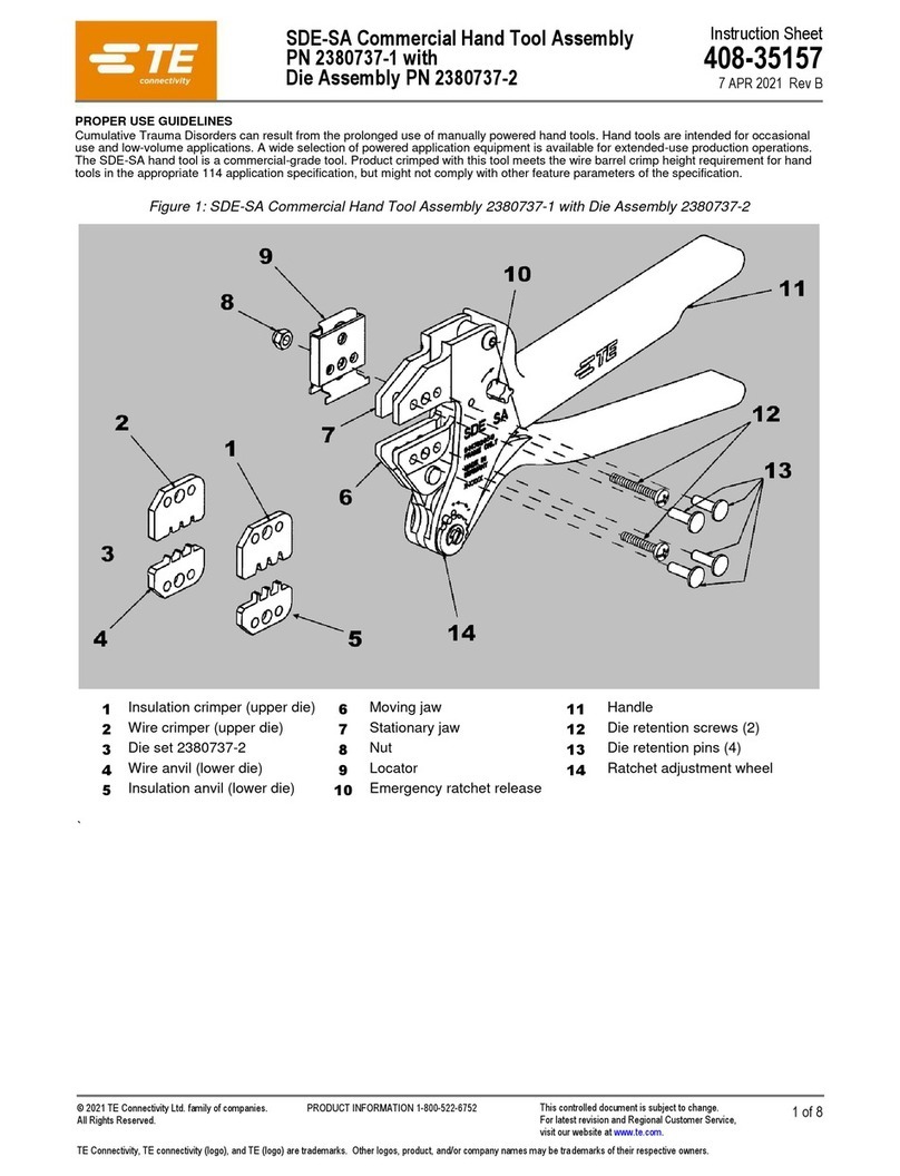
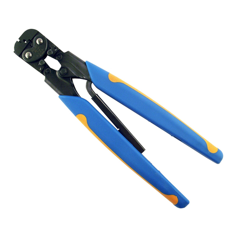
TE Connectivity SDE-SA User manual

TE Connectivity

TE Connectivity SDE-SA User manual

TE Connectivity IDC Hand tool RAST 2.5 User manual

TE Connectivity

TE Connectivity IDC Hand tool RAST 2.5 User manual

TE Connectivity SDE-SA User manual

TE Connectivity

TE Connectivity SDE-SA User manual

TE Connectivity Faston Series User manual

TE Connectivity

TE Connectivity Faston Series User manual

TE Connectivity 1213875 Series User manual
TE Connectivity

TE Connectivity 1213875 Series User manual

TE Connectivity HDP-400 Reference guide

TE Connectivity

TE Connectivity HDP-400 Reference guide

TE Connectivity 408-8569 User manual

TE Connectivity

TE Connectivity 408-8569 User manual

TE Connectivity 2394165-1 User manual

TE Connectivity

TE Connectivity 2394165-1 User manual

TE Connectivity 2368740-1 User manual

TE Connectivity

TE Connectivity 2368740-1 User manual

TE Connectivity 539682-2 User manual

TE Connectivity

TE Connectivity 539682-2 User manual

TE Connectivity HVA280-2P User manual

TE Connectivity

TE Connectivity HVA280-2P User manual

TE Connectivity ERGOCRIMP 0-1579001-6 User manual

TE Connectivity

TE Connectivity ERGOCRIMP 0-1579001-6 User manual

TE Connectivity 575937 User manual

TE Connectivity

TE Connectivity 575937 User manual

TE Connectivity 2063490-1 User manual

TE Connectivity

TE Connectivity 2063490-1 User manual

TE Connectivity 69376 User manual

TE Connectivity

TE Connectivity 69376 User manual

TE Connectivity 2031973-1 User manual

TE Connectivity

TE Connectivity 2031973-1 User manual

TE Connectivity 2392900-1 User manual

TE Connectivity

TE Connectivity 2392900-1 User manual

TE Connectivity PRO-CRIMPER III User manual

TE Connectivity

TE Connectivity PRO-CRIMPER III User manual

TE Connectivity 90117 Instruction Manual

TE Connectivity

TE Connectivity 90117 Instruction Manual

TE Connectivity AMPOWER 68361-1 User manual

TE Connectivity

TE Connectivity AMPOWER 68361-1 User manual

TE Connectivity 59974-1 User manual

TE Connectivity

TE Connectivity 59974-1 User manual

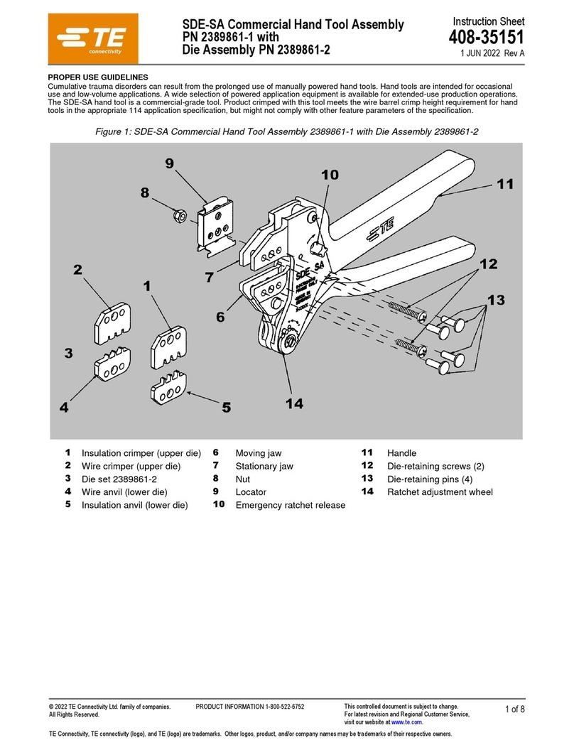
TE Connectivity SDE-SA User manual

TE Connectivity

TE Connectivity SDE-SA User manual
TE Connectivity 2391435-1 User manual

TE Connectivity

TE Connectivity 2391435-1 User manual

Popular Crimping Tools manuals by other brands

Milwaukee M18 Operator's manual

Milwaukee

Milwaukee M18 Operator's manual

molex 207129 Series Specification sheet

molex

molex 207129 Series Specification sheet

molex 63811-8100 Specification sheet

molex

molex 63811-8100 Specification sheet

Southwire RJCC-T1 quick start guide

Southwire

Southwire RJCC-T1 quick start guide

Greenlee EK1550FLX Operation manual

Greenlee

Greenlee EK1550FLX Operation manual

Apollo PEX 69PTKH00143 instruction sheet

Apollo

Apollo PEX 69PTKH00143 instruction sheet

CIMCO GENiUS 2.0 operating instructions

CIMCO

CIMCO GENiUS 2.0 operating instructions

BARTON TOOLS EC300 instruction manual

BARTON TOOLS

BARTON TOOLS EC300 instruction manual

Staubli PV-CZM Operating	 instruction

Staubli

Staubli PV-CZM Operating instruction

Burndy HYTOOL MD6 Series SAFETY OPERATING & MAINTENANCE INSTRUCTIONS

Burndy

Burndy HYTOOL MD6 Series SAFETY OPERATING & MAINTENANCE INSTRUCTIONS

BEX MultiBEX mx3 instruction manual

BEX

BEX MultiBEX mx3 instruction manual

Tyco Electronics PRO-CRIMPER III instruction sheet

Tyco Electronics

Tyco Electronics PRO-CRIMPER III instruction sheet

JST WC Series instruction manual

JST

JST WC Series instruction manual

Tyco Electronics PRO-CRIMPER III instruction sheet

Tyco Electronics

Tyco Electronics PRO-CRIMPER III instruction sheet

Staubli PV-CZM operating instructions

Staubli

Staubli PV-CZM operating instructions

Gates GC16XD Safety and operating manual

Gates

Gates GC16XD Safety and operating manual

RS PRO 445-885 Instruction leaflet

RS PRO

RS PRO 445-885 Instruction leaflet

Emerson Klauke EK 120/32CFM manual

Emerson

Emerson Klauke EK 120/32CFM manual

manuals.online logo
manuals.online logoBrands
  • About & Mission
  • Contact us
  • Privacy Policy
  • Terms and Conditions

Copyright 2025 Manuals.Online. All Rights Reserved.