TE 1059540-1 User manual
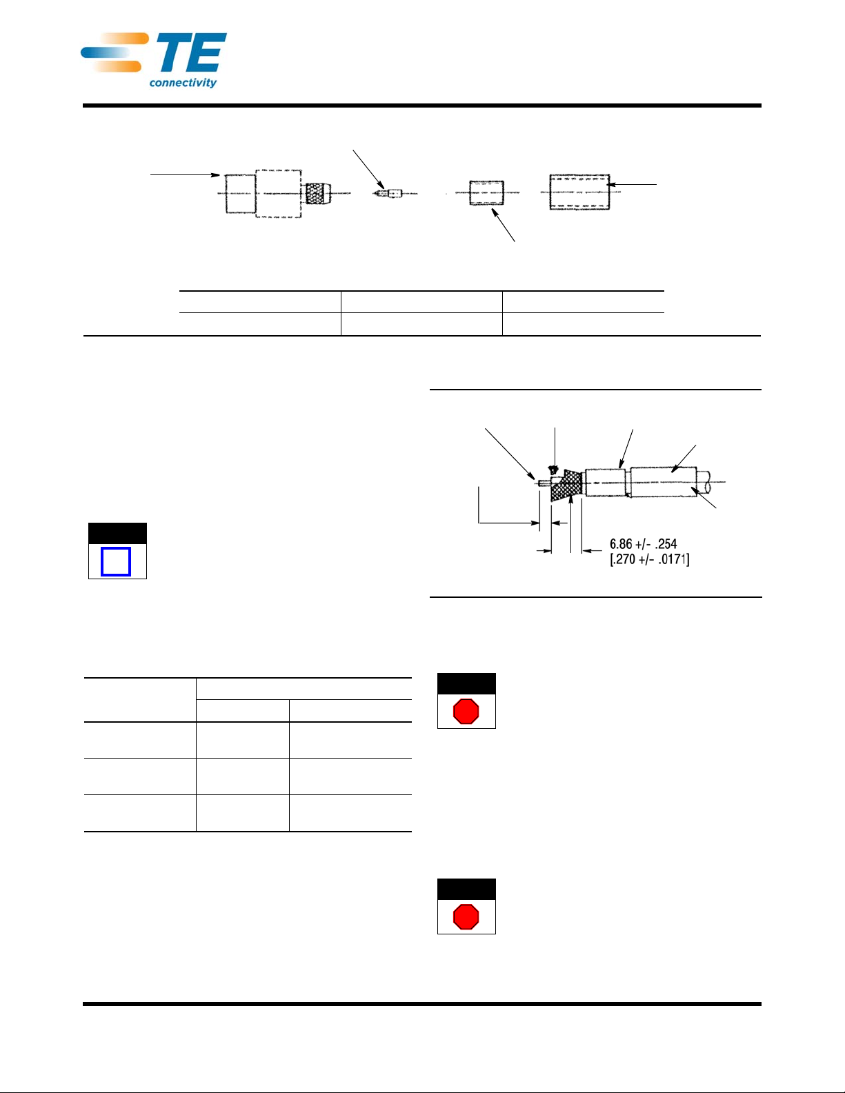
Housing
Subassembly
Center Contact
Outer Sleeve
Heat-Shrink
Tubing
TE PART NO. PREVIOUS PART NO. CABLE TYPE
1059540-1 4536-7341-02 RG55/U, 142, 223, 400
©2011 Tyco Electronics Corporation, a TE Connectivity Ltd. Company
All Rights Reserved
*Trademark
TE Connectivity, TE connectivity (logo), and TE (logo) are trademarks. Other logos, product and/or Company names may be trademarks of their respective owners.
1of 2
Instruction Sheet
TOOLING ASSISTANCE CENTER
1-800-722-1111
PRODUCT INFORMATION
1-800-522-6752
This controlled document is subject to change.
For latest revision and Regional Customer Service,
visit our website at www.te.com LOC B
408-8267
OSP* Flange Mount Cable
Jack Connector 1059540-1 20 SEP 11 Rev B
Figure 1
1. INTRODUCTION
This instruction sheet contains the assembly
procedure for OSP Flange Mount Cable Jack
Connector 1059540-1. Refer to Figure 1. These
connectors are floating rear mount, crimp attachment
type connectors that attach to the cable listed in Figure
1. Figure 1 also contains the previous part number for
the flange mount cable jack connector.
NOTE
i
Dimensions on this sheet are in millimeters [with
inches in brackets], unless otherwise specified.
Figures are not drawn to scale.
The table below references the tools required to apply
this connector. The table includes tool description, TE
part number, and the corresponding “previous” part
number.
TOOL
DESCRIPTION PART NO. CROSS-REFERENCE
TE NO. PREVIOUS NO.
Crimping Tool 1060713-1 5698-5014-54
(T-4718)
Crimping Die 1060714-1 5698-5015-54
(T-4702-1 Die No. B)
Contact Holder 1055454-1 2098-5221-10
(T-4578)
Reasons for revision can be found in Section 3,
REVISION SUMMARY.
2. ASSEMBLY PROCEDURES
2.1. Preparing the Coaxial Cable End (Figure 2)
1. Place the heat-shrink tubing and outer sleeve on
the cable.
Inner
Conductor Dielectric Heat-Shrink
Tubing
2.16 +/- .254
[.085 +/- .010]
Cable
Braid
Outer
Sleeve
Cable
Jacket
Figure 2
2. Using a knife, remove theend portion of the cable
jacket.
DANGER
STOP
To avoid personal injury, be sure to use personal
protection, including gloves, when handling a knife,
3. Trim the cable braid to length.
4. Trim the cable dielectric to length.
5. Trim the inner conductor to length.
6. Flare the cable braid.
2.2. Soldering Center Contact to Cable Inner Conductor
(Figure 3)
DANGER
STOP
The soldering equipment is hot. To avoid personal
injury, be sure to exercise caution when working
around soldering equipment.
1. Tin the inner conductor of the cable.

Center
Contact
Holder
Center
Contact
Pin
Cable
Dielectric
Solder Here
with 60/40 Solder
408-8267
2of 2
Rev B
Figure 3
2. Place the center contact in in the contact holder,
heat the center contact, and push it over the inner
conductor of the cable to rest firmly against the
cable dielectric.
3. Remove excess solder.
2.3. Crimp the Cable Subassembly to Housing
Subassembly (Figure 4)
1. Insert the cable into the housing subassembly
and seat the cable firmly in the housing
NOTE
i
Be sure that the center contact enters the pre-
assembled housing contact.
2. Slide the outer sleeve over the flared portion of
the cable braid.
3. Hold the assembly securely (with the cable
seated in the housing) and crimp the outer sleeve in
place using the appropriate crimping tool and
crimping die.
Cable
Crimping Tool
Outer
Sleeve
Housing
Subassembly
Figure 4
4. Trim and remove excess cable braid.
2.4. Completing the Termination
1. Slide the heat-shrink tubing over the cable and
housing subassembly as shown in Figure 5.
2. Apply indirect heat to the heat-shrink tubing with
a heat gun.
3. Assembly is now complete.
Heat-Shrink
Tubing
Housing
Subassembly
Completed Assembly
Figure 5
3. REVISION SUMMARY
Revisions to this instruction sheet include:
•Changed company name and logo


