Gates MC3001 Use and care manual

MC3001
OPERATING AND CALIBRATION
INSTRUCTIONS

USER GUIDE - MC3001
2
TABLE OF CONTENTS
1 - CERTIFICATE OF CONFORMITY.................................................................................................................... 3
2 - DESCRIPTION....................................................................................................................................................4
2.1 - GENERAL..............................................................................................................................................4
2.2 - CHARACTERISTICS.............................................................................................................................4
2.3 - WORKING PRINCIPLE..........................................................................................................................5
2.3.1 - Hydraulic system.......................................................................................................................5
2.3.2 - Electrical system.......................................................................................................................7
2.3.3 - Crimp head...............................................................................................................................8
3 - INSTRUCTIONS FOR USE...............................................................................................................................10
3.1 - SAFETY................................................................................................................................................10
3.2 - UNPACKING - INSTALLATION.............................................................................................................10
3.3 - OPERATING INSTRUCTIONS.............................................................................................................12
3.4 - ADJUSTMENT/CALIBRATION..........................................................................................................13
3.5 - DIE POSITIONING AND INSTALLATION............................................................................................13
4 - MAINTENANCE................................................................................................................................................14
4.1 - MAINTENANCE...................................................................................................................................14
4.1.1 - Die lubrication.........................................................................................................................14
4.1.2 - Checking and replacing the oil................................................................................................15
4.1.3 - Cleaning the swaging head.....................................................................................................15
4.2 - SPARE PARTS....................................................................................................................................16
4.2.1 - Spare machine parts...............................................................................................................16
4.3 - TROUBLESHOOTING.........................................................................................................................18
4.4 - WARRANTY LIMITATIONS.................................................................................................................. 19

USER GUIDE - MC3001
3
1 - CERTIFICATE OF CONFORMITY
EC DECLARATION OF CONFORMITY
The manufacturer, the undersigned : GATES
hereby declares that the new equipment described below:
MC3001 - serial number:
complies with the machinery directive and the specifications given by GATES and with the regula-
tions regarding health and safety at work, as applicable.
Drawn up: date:
signature:
Machine started on: by: place:

USER GUIDE - MC3001
4
2 - DESCRIPTION
2.1 - GENERAL:
YouhavejustacquiredaGATESMC3001poweredcrimper.Itisnecessaryyouadheretotheenclosedinstructions
for best performance.The MC3001has been designed specifically for crimping Gates hoses and couplings which
are used constantly in today’s industry, agriculture and public works. This user guide contains all information
concerning the operation, use and maintenance of your MC3001.
2.2 - CHARACTERISTICS:
Crimping power: 210 tonnes (maximum measured).
Pressure:305 bar during crimping, 150 bar during retraction.
Motor: 3 kW, 8 A at 380 V 3-phase.
4 kW, 26 A at 220V 1-phase.
Dimensions:H 650 xW 390 x L 640 mm.
Weight: 180 kg with oil.
Capacity: braided hose from 3/16" to 1" 1/4
multiple-plied metal reinforced hose from 1/4" to 1 1/4" (not skived)
Noise levels: 71 dB.
Oil tank: 10 litres.
Pump: gear type.
Die travel: 14 mm working travel and 38 mm maximum travel.
Adjustment: by micrometer screw with numerical display and electrical stop.
Crimping: by pressing push-button.
Crimping stop: automatic according to adjustment.
Retraction: by pressing push-button.
Retractionstop: by releasing push-button.
Cycle time: 12 seconds for 3-phase 380V crimper.
16 seconds for 1-phase 220V crimper.
Tooling: GATES die sets.
These specifications are nominal and must not be used for inspection.
Options:-Machine table + die rack + quick change tool
(ref. MC5000 - 10798)
-Quick change tool + die rack
(ref. MC5000 - 10354)

USER GUIDE – MC3001
2.3. – WORKING PRINCIPLE:
This machine is comprised of 3 main systems: the hydraulic circuit, the crimping head with numerical
set stop for crimp adjustment, and the electrical system.
2.3.1. – HYDRAULIC SYSTEM:
This supplies the energy necessary to move the dies.
Composition:
The hydraulic circuit is comprised of (see figures 1 and 2)
- a drilled block (1)
-a pressure limiter (2)
- a pilot valve (3)
- a control valve (4)
- a motor (5)
- a pump (6)
- a suction filter (7)
- an oil tank (8)
Figure 1 : Hydraulic circuit diagram
5

USER GUIDE - MC3001
6
Working principle:
In the non-actuated state (such as shown in figure 1), the motor drives the pump which continuously supplies the
circuit with oil.The control valve (4) is in position middle (see figure 1). The oil is in a closed circuit and returns to
the oil tank (8).
During crimping, the control valve (4) is in the RH position. The connection P to B on the control valve (4) is estab-
lished.The crimping chamber is supplied with oil.When pressure is equal or greater than the required
pressure, excess oil is returned to the oil tank (8) via the pressure limiter (2).
Oil in the retraction chamber is evacuated to the oil tank (8) via the control valve (4) from A to T.
During die retraction, the control valve (4) is in the LH position.The connection P to A on the control valve is estab-
lished.The die retraction chamber is supplied with oil.A system in the bell housing allows the pressure to reduce
during the return. Oil in the crimping chamber is returned to the oil tank (8) via the connection B toT on the control
valve (4).The volume of oil in the crimping chamber being larger, oil is also evacuated via the pilot valve (3).
Figure 2 : View of drilled block.

USER GUIDE - MC3001
7
2.3.2. - ELECTRICAL SYSTEM:
The electrical system supplies the motor and control valve.
Note: Spare fuses are attached to the switch cable in the electrical enclosure of the machine.
Composition:
The electrical system is comprised of (see figure 3):
For supply section:
- an electric motor (1)
- a thermal breaker (2)
- a general disconnecting switch "0-1" (3)
- a motor contactor (14)
For control section:
- 2 fuses 0,25 A am (4) and 4A gi (5)
- a micro-switch (6)
- two push-buttons (7) and (8)
- two control valve coils (9) and (10)
- two indicator lamps (11) and (15)
- a transformer (12) 380-220/24 V
- a push-button (13)
- a motor contactor (14)
- a emergency stop (16)
Figure 3 : Electrical circuit diagram.
1
2
3
4
5
6
7
8
9
10
11
12
13 14
15
14
16
/1
(3-phase)
(3-phase)


USER GUIDE - MC3001
9
Working principle:
The bell housing (8) and piston (10) can be compared to a double acting hydraulic ram. Crimping consists in
transforming a linear displacement at constant speed, that of the piston (10), into a two speed radial displacement:
resulting in a rapid approach speed and a slower crimping speed.
These two speeds are obtained via two slopes on the piston (10) and the die-carriers (6). The gentle slope en-
sures, for equal thrust on the piston (10), a slower displacement and higher crimping power.
The main elements of the crimper, made from special steel, are heat treated in order to ensure that they will
withstand high stresses, and to reduce wear through contact or friction.
Guidance in movement is ensured via two composite rings (made from bronze-charged teflon).
Sealing is obtained through 3 composite joints (made from PTFE). Also, in the unlikely event of any leaks, an oil
trap ring (12) at the rear of the bell housing directs oil back to the tank. A similar device is incorporated into the face
flange (5).
The numerical crimp adjuster, mechanically activated by the hollow piston (10), electrically stops the crimping
operation. For that purpose, it is equipped with a microswitch (3) which activates the control valve.
Adjustment of the crimp diameter is via a micrometer (2).
Rotationof the micrometer changes the contact rod position (4),thereby allowingfor preciseadjustment ofthe final
crimp diameter.

USER GUIDE - MC3001
10
3 - INSTRUCTIONS FOR USE
3.1 - SAFETY:
The machine must be installed on a bench or on a stable base.
Do not put your hand in the crimping head during operation.
Do not modify technical characteristics of the machine (pressure or others).
When performing any kind of maintenance upon the electrical system,
ensure that the machine is disconnected from the power supply.
Do not cover the electric motor ventilator.
Disconnect the machine from electrical supply when working on the dies,
die-carriers or intermediate dies.
3.2 - UNPACKING - INSTALLATION:
Unpack the machine without destroying the packaging. From then on, the machine should only be transported in its
original packaging. Please retain for future use.
To remove the lid from the box remove the screws at the bottom of the lid; lift the lid off the box. Place webbings
under the machine, or raise it with a lift truck. Never lift the machine by the working head or any of
its component parts.
For best use and less operator fatigue it is advisable to secure the machine horizontally on a base
approximatively .75 metres in height.
Once you have positioned the machine, remove the blanks from the oil tank filling cap. Wait for 20 minutes, and
check the oil level using the dip stick attached to filling cap.
The machine should only be connected to a safe electrical circuit, in accordance with the latest European guide-
lines.
Electrically connect the motor making sure it rotates in the direction indicated by the arrow located on the casing.
Check this rotation by quickly switching the main switch on and using the emergency stop.
Important:faulty motor rotation can damage the pump.To change the direction of motor rotation, reverse the two
phase wires to the mains plug.The machine has been preconnected to run on a 380V 3-phase mains supply.To
connect to a 220 V 3-phase or 1-phase mains supply, please consult us.
Install the gauge setting mechanism on the crimp head face flange. Do this with the machine disconnected
from the mains supply.For correct installation, display 000 on the counter dial byturning the counter knob
counterclockwise.Attach the micrometer gauge assembly using the two screws with springs supplied, ensuring
the counter is the correct way up.
Connect the electrically operated micrometer gauge assembly plug to the socket behind the front panel.
Unpacking and/or installation which do not conform to these procedures
will render the warranty void.
To be connected by a qualified electrician only,

USE USERGUIDE–MC3001
8
7
3
6
5
4
1
2
1. Crimper flange face 5. Disengage die button
2. Gauge setting mechanism 6. On button
3. Finished crimp indicator light 7. Emergency stop button
4. Engage die button 8. Mains on/off switch
Fig 4.a : Identification diagram
11

USER GUIDE - MC3001
12
3.3 - OPERATING INSTRUCTIONS:
Ref - fig 4.a
1. Turn the main switch (8) to position 1 and press the ON button (6).
2. Press the disengage die button (5) in order to fully open the die carriers.
3. Set gauge at "150" +/- 10.
5. Press emergency stop button (7).
6. Remove set of dies required from die rack using quick change tool.
7. Insert die set into die carriers.
8. Pull trigger on quick change tool and remove, leaving dies in place and ready to use.
9. Unlock the emergency stop button (7) and press the ON button (6).
11. Set the gauge setting mechanism (2) to the correct setting as indicated on the crimp CD for the particular
hose and connector being crimped.
12. Position the hose and the connector between the dies in the crimp head.
13. Place the ferrule in the position as specified on the crimp CD.
14. Press the engage die button (4) to carry out the crimping operation until the finished crimp indicator
light (3) lights up.
15. Press the disengage button (5) to release the crimped assembly.
16. Check the crimp diameter of the ferrule with a vernier or micrometer*. The measured crimp diameter must be
4. Press engage die button (4) until machine automatically stops.
within the tolerance published on the crimp CD. If not, the hose assembly cannot be used and adjustment
will be required. Correct the gauge setting if required. In order to decrease the crimp diameter reduce the
value of the gauge setting mechanism (2); reverse procedure to increase crimp diameter.
*Always use verniers or micrometers that are graduated to 0.001"/0.02mm or smaller.
N.B. To change die set, perform steps 1-5. If dies do not have a small gap between each other they will
not release from the intermediate dies, therefore it will be necessary to increase the gauge setting by
10 and perform steps 1-5 until a working gap appears, thus allowing the die set to be removed from the
the machine.
A rotation of 7 units on the gauge setting mechanism is equal to a change of 0.10mm on the crimp diameter.
Gauge settings must be considered a guide to achieving the correct crimp diameter.
Actual crimp diameters must be within the specified crimp tolerance.
10. Press disengage button (5).

USER GUIDE – MC3001
3.4. – ADJUSTMENT / CALIBRATION
Before delivery each machine is calibrated and should be ready for use upon receipt.
However, machine calibration should be checked on a monthly basis and when gauge
settings consistently produce diameters outside the crimp diameter tolerance.
Calibration procedure is as follows:
To calibrate using calibration shell 7482-19860:
-Place die set D33 in the machine.
-Set the gauge setting mechanism to 200.
-Crimp the calibration shell 7482-19860.
-Measure the crimped diameter of the calibration shell – it should read 26.0 +/-
0.1mm
-If the crimp diameter is outside the stated dimensions, it is necessary to
recalibrate the machine as follows:
1. Isolate the machine from power supply.
2. Note by how much the measured crimp diameter differs from the required
26.0mm calibration diameter.
3. Unscrew the two socket head screws that hold the gauge setting mechanism
in place with a 3mm Allen key and remove the unit.
4. Calibration adjustment is now via the 6mm screw and locknut. One full turn of
the screw clockwise (when viewed from the screw end) will reduce the crimp
diameter by 0.4mm. Turning the screw anti-clockwise increases the crimp
diameter 0.4mm.
5. Unlock the locknut and turn the screw the required amount according to the
difference between the achieved and the required crimp diameter.
6. Lock the locknut and replace the gauge setting mechanism, tightening the two
socket head screws.
7. Crimp a new calibration shell and check that the correct crimp diameter has
now been achieved.
8. If the required crimp diameter is not achieved, repeat the recalibration
process.
3.5. – DIE POSITIONING AND INSTALLATION
Figure 5 : location 1 Figure 6 : location 2
For straight couplings For angled couplings
or
13

USER GUIDE - MC3001
14
4 - MAINTENANCE
4.1 - MAINTENANCE:
4.1.1 - DIE LUBRICATION:
Friction on the dies whilst crimping is very important. For this reason, it is necessary to lubricate the bearing
surface of the die-carriers on the piston regularly. Indeed, an insufficiently lubricated machine could seize, or
the pistons and die-carriers could be subjected to increased wear.
To achieve correct lubrication, grease with a 60% concentration of molybdenum di-sulphide must be used
(this product is supplied with the machine and can be obtained from GATES, Part No. 7482-19227).
Lubricate every 100 crimping operations as follows:
-Shake the aerosol can, held upside down, for 1 minute (this amount of time is necessary for such a
thick product to be vaporised properly).
- Advance the die-carriers on the rapid cone. The die-carriers should be 5 mm above the face flange
(see figure 7).
Figure 7 :
Position of die-carriers for lubrication.
-Introduce the aerosol can plastic tube in the hole located at the rear of the die-carriers
(lubrication point N° 1 - see figure 8).
Figure 8 :
Lubrication point N° 1.
Recommended grease:
see above.
- Grease the piston through the holes of each die-carrier.

USER GUIDE - MC3001
15
- Completely close the die-carriers.
- From front of machine, lubricate between the die-carriers and the face flange
(lubrication point N° 3 - see figure 10).
Figure 10 :
Lubrication point N° 3.
Recommended grease:
see above.
- From the rear of the bell housing, spray the grease all around the cone (lubrication point N° 2 - see figure 9).
Figure 9 :
Lubrication point N° 2.
Recommended grease:
see above.
4.1.2 - CHECKING AND REPLACINGTHE OIL:
-Regularly check the oil level — about every 500 crimping operations.
- Empty the oil tank each year and replace the used oil with new oil (the machine is delivered with a full tank of
hydraulic oil type ISO HV 32).
4.1.3 - CLEANING THE SWAGING HEAD:(DISCONNECT FROM POWER SUPPLY)
- Regularly dismantle the face flange and the die-carriers — about every three months. This is necessary to
ensure that metallic/other particles are removed before causing damage to machine parts.
Dismantle as follows:
-Put die set N° 35 into location 1, Fig. 5, with dies reversed so that they protrude past the face flange.
- Remove gauge setting mechanism - the crimper must be fully opened.
- Remove the 12 cap head screws from the face flange.
- Carefully remove the flange with the 8 die-carriers.
- Clean and lubricate all surfaces using recommended grease.
-Reassemble the flange and the die-carriers. Ensure that it is correctly located for the gauge setting mechanism.
-Tighten the 12 screws with a torque wrench set at 28 MKg.(Tighten opposing screws, spreading the force,
This operation can be difficult for an inexperienced mechanic.
When in doubt, don’t hesitate to contact your Gates representative.
thus reducing the possibility of deforming the flange.)

USER GUIDE – MC3001
4.2. – SPARE PARTS:
Note: Tampering with the machine during the warranty period will render the latter void.
All orders for spare parts must state reference, description and quantity required.
Example:
Reference: MC3000-4622
Description: PISTON
Quantity: 1
4.2.1 – SPARE MACHINE PARTS(seeFigure 11):
Position REF. Description P/N Quantity
Pos. 4 / fig. 1 MC3000-004 Control Valve 7482-19987 1
Pos. 6 / fig. 1 MC3001-11104 Gear Pump 8000-10082 1
Pos. 10 / fig.11 MC3000-127 Oil trap ring 7482-19717 1
Pos. 9 / fig. 11 MC3000-1283 Piston flange 7482-19718 1
Pos. 2 / fig. 3 MC3000-1512
MC3000-9574
Thermical circuit breaker 3-phase
Thermical circuit breaker 1-phase
7482-19719
7482-19963
1
Pos. 8 / fig. 11 MC3000-152 Composite seal ø 190 mm 7482-19720 1
Pos. 14 / fig. 11 MC3000-154 Composite seal ø 200 mm 7482-19721 1
Pos. 5 / fig. 11 MC3000-189 Piston ring 7482-19722 1
Pos. 7 / fig. 11 MC3000-190 Piston flange ring 7482-19723 1
Pos. 12 / fig. 3 MC3000-20 Electrical transformer 7482-19724 1
Pos. 4 / fig. 11 MC3000-291 O’ring R No. 67 7482-19725 1
Pos. 16 / fig. 11 MC3000-343 CHC M14*50 12-9 screw 7482-19726 12
Pos. 3 / fig. 11 MC3000-4622 Piston 7482-19727 1
Pos. 15 / fig. 11 MC3000-4640 Head flange 7482-19728 1
Pos. 1 / fig. 3 MC3000-005 Motor 3Kw 380V 3Ph 7482-19729 1
Pos. 1 / fig. 11MC3001-11409 Masterdie 8000-10091 1
Pos. 13 / fig. 11 MC3000-59 Head 7482-19731 1
Pos. 5 / fig. 3 MC3000-762 Fuse 4A gi 7482-19732 1
Pos. 4 / fig. 3 MC5000-766 Fuse 0,50 A am 7482-19037 1
MC3000-82 Pilot valve (machines before 1173) 7482-19734 1
Pos. 14 / fig. 3 MC3000-946 Contactor 7482-19735 1
MC3000-HEAD Standard exchange crimping head 7482-19352 1
MC5000-1419 Body’s switch of push button 7482-19740 1
Pos. 6 / fig. 11 MC5000-153 Composite seal ø 260 mm 7482-19742 1
MC5000-1666 Signal’s body 7482-19743 1
MC3001-11192 Magneticdie changing tool 8000-10083 1
Pos. 1 / fig. 4 MC5000-21 Revolution counter button 7482-19228 1
MC5000-36 Bulb 7482-19665 1
Pos. 18 / fig. 11 MC5000-4553 Tightening ring 7482-19226 8
Pos. 11 / fig. 11 MC5000-4586 Gauge 7482-19143 1
MC3001-10432 Die retaining pin 8000-10085 8
MC3001-10433 Die retaining pin 8000-10090 8
MC5000-11110 Die Pin B 8000-10066 1
Pos. 2 / fig. 11 MC5000-5036 Spring master dies 7482-19231 16
Pos. 17 / fig. 11 MC5000-54 Die nipple 7482-19033 8
Pos. 2 / fig. 1 MC5000-5691Pressure limiter (machines after 1173) 7482-19986 1
Pos. 13 / fig. 4MC5000-10428 Protection gauge 8000-10081 1
Pos. 3 / fig. 4 MC5000-5845Main contactor 7482-19985 1
Pos. 13 / fig. 3 MC5000-6004 ON (lit) push button 7482-18510 1
Pos. 7,8 / fig. 3 MC5000-6005 Green push button 7482-18509 2
Pos. 16 / fig. 3 MC5000-6008 Emergency stop 7482-19675 1
Pos. 11,15/ fig. 3 MC5000-6009Yellow signal 8000-10013 1
MC3001-10182 Set of 8 foam pads 7482-19766 1
16


USER GUIDE - MC3001
18
4.3 - TROUBLESHOOTING:
Problem Probable cause Possible solutions
The crimper won’t open or Lubrication error Clean and lubricate the crimper (see
does not crimp sections 4.1.1 and 4.1.3).
The control valve is not piloted Check the electrical circuit: fuses,
plugsandconnections,feeding of the
control valve bobbin.
Crimping power is not sufficient Wrong choice of dies Usethediesasspecifiedby thecrimp-
ing information provided with the ma-
chine.
Inadequate hydraulic pressure Calibration of high pressure to 320
bars during crimping (set in factory).
Unlockthedischarge valves if neces-
sary.
Hydraulic leaks Check and replace malfunctioning
seals.
The control valve does not work Maintain or replace the control valve.
Dies move out of positionDies are incorrectly installedReplace damage pins or
reposition die retaining pins.
Electrical motor makes 2-phase operation Check electric supply, fuses
abnormal noise and connections.

USER GUIDE - MC3001
19
4.4 - WARRANTY LIMITATIONS:
Gates machines are guaranteed against defects and faulty workmanship for a period of one year from date of
purchase.
During the period of warranty, Gates will repair (or replace as the case may be) free of charge all faulty parts,
provided the machine is returned to the works. This warranty will not apply in the case of accidental damage,
misuse or if the machine has been subjected to repairs or modifications by persons other than Gates. Gates
cannot be held responsible for any damage or injury direct, indirect or consequential to the use of its machines, nor
after express or implicit termination of warranty.
This warranty replaces all other warranties including implicit warranties.
Every effort has been made to ensure the accuracy and comprehensiveness of the informations included in this guide.However,Gates
cannot be held responsible for errors or omissions and alterations which have occured after release for printing; or if Gates products are
used in special or exceptional circumstances without prior consultation with and clearance from a Gates representative for verification of
the planned usage.
For more information, please contact:
Gates Hydraulics Ltd
Station Road
St Neots, Huntingdon, Cambs.
PE19 1XA, UK
TL: (44) 01480 / 25 50 00
FX:(44) 01480 / 25 53 50
Gates Hydraulique S.A
B.P.14
F - 69881 Meyzieu-Cedex
TL:(33) 04 72 45 12 12
FX:(33) 04 72 02 85 24
Gates Europe N.V.
Dr.Carlierlaan 30
B - 9320 Erembodegem
TL:(32) 053 / 76 27 11
FX:(32) 053 / 76 27 13
The world's most trusted name in
belts and hose
Table of contents
Other Gates Crimping Tools manuals

Gates
Gates GC20 Instruction Manual
Gates
Gates GC32-XD User manual
Gates
Gates GC32FLEX Guide

Gates
Gates GC32TSi Guide

Gates
Gates GC96 User manual
Gates
Gates MobileCrimp 4-20 Installation manual
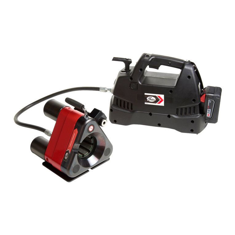
Gates
Gates GC16XD Installation manual
Gates
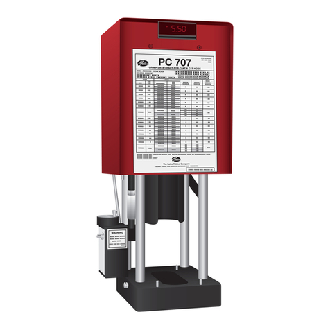
Gates Power Crimp 707 Installation manual

Gates
Gates MCX50 Use and care manual

Gates
Gates GC16XD Installation manual
Popular Crimping Tools manuals by other brands

TE Connectivity
TE Connectivity CERTI- CRIMP Series instruction sheet
koban
koban KEB-611 manual

molex
molex 63816-1900 Operation manual

PRECISETOOL
PRECISETOOL XCXY-02 instructions
TE Connectivity
TE Connectivity TERMI-FOIL 68026 instruction sheet

TE Connectivity
TE Connectivity PRO-CRIMPER III instruction sheet
