manuals.online logo
Brands
  1. Home
  2. •
  3. Brands
  4. •
  5. Teac
  6. •
  7. Accessories
  8. •
  9. Teac TC-USR(T)23-G3 User manual

Teac TC-USR(T)23-G3 User manual

D01336701A
Z
Strain gauge load cell Instructions for Use
TC-USR(T)-G3
Compression Load Cell
Introduction
Thank you for purchasing the TC-USR(T)-G3 load cell.
Please read this document completely before using this
load cell to achieve its best performance and ensure safe
and proper operation.
Included accessories
If anything is missing or damaged, contact the retailer
where you purchased the product.
Test report × 1
Instructions for Use (this document) × 1
Company names and product names in this document are the trademarks
or registered trademarks of their respective owners.
IMPORTANT SAFETY INSTRUCTIONS
VWARNING
If something abnormal occurs
In the unlikely event that the product produces smoke, a
strange smell or noise, for example, continuing to use it in
this abnormal state could cause fire or electric shock. After
cutting off the power, confirm that smoke is no longer being
produced. Then, request repair from the retailer where you
purchased the product.
Do not open the cover.
Never remove the cover from this unit. Doing so could
cause electric shock. Request inspection and repair from
the retailer where you purchased the product. Do not
alter this unit. Doing so could cause fire or electric shock.
Do not put foreign objects or water, for example,
into the unit.
Do not place a container that holds water, for example,
on top of this unit. Liquid overflowing or entering the unit
could cause fire or electric shock.
Do not use the unit with any power supply voltage
other than that specified.
Do not use the unit with any power supply voltage other than
that specified. Doing so could cause fire or electric shock.
VCAUTION
Unsuitable installation locations
Do not place the unit in the following types of locations.
Doing so could cause fire or electric shock.
oLocations where it might be exposed to smoke or steam,
such as near a kitchen table or humidifier
oUnstable locations, including unsteady stands and
tilted places
oLocation that are very humid or dusty
oLocations that are exposed to direct sunlight
When not using the unit for a long time
For safety, cut the power supply when not using this
unit for a long time.
Do not operate a damaged unit.
Precautions for use
oThis unit is not built to be water or splash resistant,
and it cannot be used in conditions when the relative
humidity is high. Moreover, use in atmospheres with
corrosive gases should be avoided.
oBe careful to prevent water, oil and other substances
from getting on the unit.
oAvoid use in conditions where condensation could occur.
oConnect cores to the load cell after discharging (elim-
inating) static electricity from your body.
oIf the surrounding temperature changes suddenly, the
values output by this device could become unstable,
making accurate measurement impossible. (This could
occur, for example, in a location blown by warm or cold air.)
oConduct load calibration periodically.
Installation procedures
oInstall this unit in a place where the structure is level
and can sufficiently bear the load being used.
oScrew holes for attachment are located in four places.
oThe screw hole dimensions are different for each load
cell rated capacity. The screw hole dimensions are
shown in the table below.
Model Screw hole
dimensions
Tightening
torque
TC-USR(T)23-G3 M2 through 0.088N·m
TC-USR(T)29-G3 M3 through 1N·m
TC-USR(T)30-G3 M2.6, depth 3 0.18N·m
TC-USR(T)34-G3 M4 through 3N·m
oThe TC-USR(T)17-G3 does not have attachment
screw holes.
Remove any oil from the mounting surface and attach
it with double-sided tape or adhesive, for example.
Dimensions in millimeters (mm)
ATTENTION
Installation surface
Do not use the central indentation
as an installation surface.
Precautions when placing loads on the
unit
oMake sure the load is perpendicular to the surface to
which this unit is attached.
oApply the load so that it is centered on the center of
the unit. If the load is not centered (eccentric load),
twisting, for example, and measurement errors could
occur. This could even result in damage.
F1 F2F
F is the correct load orientation
F1 is an eccentric inclined load
F2 is an eccentric load
oBe careful to avoid turning and twisting from lateral
loads. This could cause troubles like those described
in the previous item.
oBe careful to avoid applying loads that exceed the
rated capacity. In particular, use caution when there are
vibrations because loads that exceed the rated capacity
could occur due to sympathetic vibrations, for example.
oIf the load receiving area (spherical surface) is contacted
by something that is at a different temperature and
the load is increased, the values output by this device
could become unstable, making accurate measurement
impossible. In such a case, wait until the temperature
difference ceases to exist before measuring.
Electrical connection of load cell with
built-in TEDS
oConnect as shown in the illustration below. Incorrect con-
nections could result in inability to balance and in errors
occurring in the output voltage when loads are applied.
Using a cable with bare lead wires
Red Input (+)
Black Output (−)
Blue Input (−)
White Output (+)
Orange TEDS signal (+)
Green TEDS signal (COM)
Shield
TEDS
oThis unit has a built-in TEDS function.
The orange and green cores in the cable and the F and
G pins in the connector are wired for TEDS.
oThis unit does not support remote sensing.
Since products that support remote sensing use the
same cables and connector pins as TEDS, be careful not
to try mistakenly to use these pins for remote sensing.
See the operation manuals of indicators and strain
amps that support remote sensing for how to connect
sensors with those units.
oThe shield is not connected to the main body of this
product. For this reason, if grounding is necessary because
of external noise, for example, arrange to ground the
shield to a part other than the body of this unit.
oSince the cable is directly connected to this unit, use a spe-
cialized cable to increase the length. (Please consult with us.)
oWhen conducting insulation resistance tests, limit them
to the red, black, blue and white cores. Do not apply to
the TEDS cores (orange and green).
Using a connector (optional)
A Input (+)
B Output (−)
C Input (−)
D Output (+)
F TEDS signal (+)
G TEDS signal (COM)
E Shield
NDIS-compatible connector
TEDS
TEDS overview
TEDS (Transducer Electronic Data Sheet) is a memory chip
that can electronically read and write sensor-specific data.
The TEDS built into this unit has serial number, load cell rated
output and manufacturer name data recorded on it. By
connecting an indicator that supports TEDS, the TEDS data
of the connected load cell will be automatically read and
equivalent input calibration will be completed. (For details,
read the operation manual of the connected indicator.)
Refer to the connection diagrams in “Electrical connection
of load cell with built-in TEDS” as well as the operation
manual for the indicator being connected for procedures
to make connections.
TEAC indicators that support TEDS include the TD-01
Portable, TD-700T, TD-260T, TD-275T, TD-280T and TD-9000T.
For details, inquire at a shop that handles these products.
If not using the TEDS function, do not connect the orange
and green load cell cores.
Moreover, take measures to prevent the orange and green
cores from touching other terminals.
Data recorded in TEDS are tested values from calibration
conducted at room temperature during inspection before
shipping from our company.
Load cell output will be affected by the environmental tem-
perature where used, even when within the compensated
temperature range established in the specifications. Although
load cell output is calculated from the calibration value saved
in TEDS, when the environmental temperature differs greatly
from room temperature, the temperature impacts increase on
the zero point and the output. For this reason, consideration
of the effect on output voltage is necessary. Output voltage
changes will be within the specification range as long as the
unit is used at temperatures within the specification range.
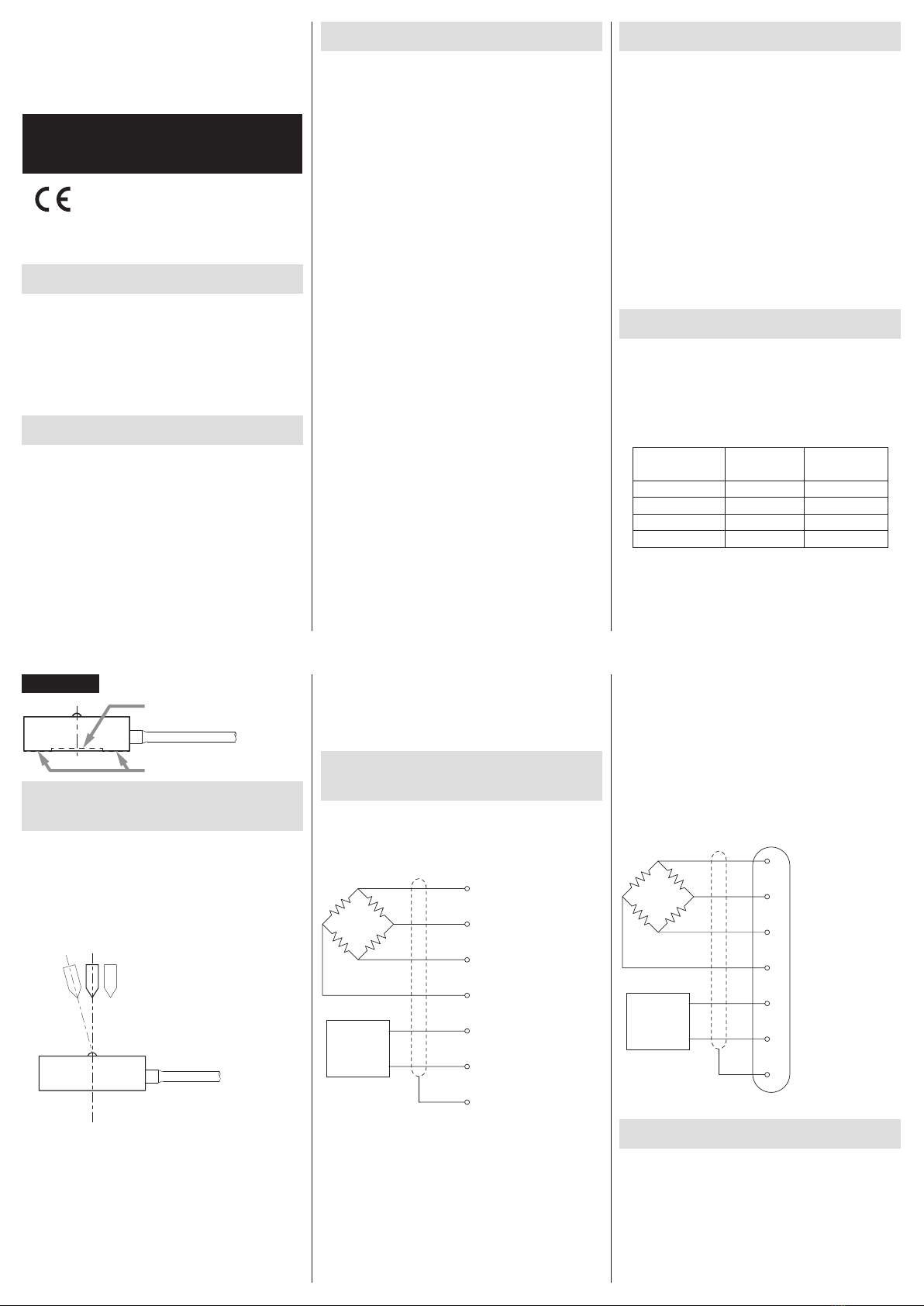
When using the TEDS function
This product’s cores for TEDS (orange and green) are
protected by a plastic cover as shown in the illustration.
This is to prevent miswiring and contact with other connec-
tors during use, for example, which could cause shorting.
To use the TEDS function, remove the tip of the plastic cover,
following the perforations, from the end of the cables. Then,
connect the TEDS cores (orange and green) to the indicator.
Refer to“Electrical connection of load cell with built-in TEDS”
for how to connect each wire.
Cores for sensor
Load cell cable
Protective
plastic
Perforations
Cores for TEDS
(orange and green)
When not using the TEDS function
If not using the TEDS function, remove the entire protective
plastic cover and cut off the TEDS cores (orange and green)
around where the plastic cover was attached to the cable.
If you use it without removing these cores, do not remove
the protective plastic or make other arrangements to prevent
the cores from touching other places.
Refer to“Electrical connection of load cell with built-in TEDS”
for how to connect each wire.
NOTE
Explanations related to TEDS are available on our website.
https://loadcell.jp/en/info/teds.html
ATTENTION
Since the protective plastic and tag are not suitable for
the entire temperature range of this unit’s specifications,
do not expose them to high temperatures.
Handling after use
oWhen moving this unit while it is installed, take protective
measures to prevent it from being shaken or subjected
to excessive external forces.
oWhen storing it, keep it in a dry place where it will not
be exposed to water or oil, for example.
Specifications
Rated capacity: 0.5N, 1N, 2N, 5N, 10N, 20N, 50N, 100N,
200N, 500N, 1kN, 2kN
Overload limit: 300% R.C.
500% R.C. (TC-USR(T)17-G3, TC-USR(T)23-G3)
Safe overload rating: 150% R.C.
120% R.C. (TC-USR(T)30-G3)
Rated output: 0.5mV/V or higher
0.75mV/V or higher (TC-USR(T)29-20N-G3 to
TC-USR(T)29-100N-G3 and TC-USR(T)34-G3)
Linearity: 0.1% R.O.
0.3% R.O. (TC-USR(T)17-G3, TC-USR(T)23-G3)
Hysteresis: 0.1% R.O.
0.3% R.O. (TC-USR(T)17-G3, TC-USR(T)23-G3)
Repeatability: 0.1% R.O.
0.3% R.O. (TC-USR(T)17-G3, TC-USR(T)23-G3)
Zero balance: ±10% R.O.
Safe excitation voltage: 6V
Input terminal resistance:
420 ±20Ω
390 ±20Ω (TC-USR(T)29-10N-G3 to TC-USR(T)29-100N-G3,
and TC-USR(T)34-200N-G3 to TC-USR(T)34-2KN-G3)
Output terminal resistance: 350 ±20Ω
Insulation resistance: 1000MΩ or more (DC 50V)
Compensated temperature range: 0 to 60°C
Permissible temperature range:
−10 to 60°C
−5 to 70°C (TC-USR(T)30-0.5N-G3 and TC-USR(T)30-1N-G3)
Temperature effect on zero balance: 0.3% R.O./10°C
Temperature effect on output:
0.1% R.C./10°C
0.3% R.C./10°C (TC-USR(T)30-0.5N-G3 and
TC-USR(T)30-1N-G3)
Cable: Ø3mm 6-core robot cable
3m with bare lead wires
Body material:
stainless steel
aluminum (TC-USR(T)30-G3, TC-USR(T)17-10N-G3,
TC-USR(T)23-10N-G3, TC-USR(T)29-10N-G3)
Environmental compliance: RoHS (10 substances)
Other: built-in TEDS
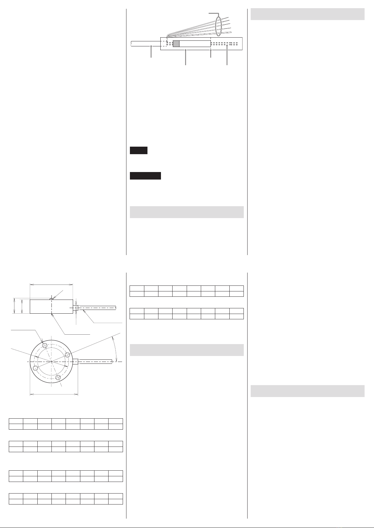
Dimensional drawings
Dimensions in millimeters (mm)
g
Attachment screws
(placed at equal 90°
intervals)
a
Ø 3
cable
(3m)
P.C.D. f
Ø d
b
Ø e
c
Stopper
h
TC-USR(T)17-2N-G3, TC-USR(T)17-5N-G3
a b c d e f g h
5 6 SR1 17 (3.5) - 22.5 -
TC-USR(T)23-2N-G3, TC-USR(T)23-5N-G3
a b c d e f g h
5.5 6.5 SR1 23 (3.5) 20 28.5 22.5°
TC-USR(T)29-10N-G3, TC-USR(T)29-20N-G3,
TC-USR(T)29-50N-G3, TC-USR(T)29-100N-G3
a b c d e f g h
8.5 9.5 SR1 29 (3.5) 24 33 22.5°
TC-USR(T)30-0.5N-G3, TC-USR(T)30-1N-G3
a b c d e f g h
12.5 13.5 SR1 30 (3.5) 22.5 35 45°
TC-USR(T)34-200N-G3, TC-USR(T)34-500N-G3,
TC-USR(T)34-1KN-G3
a b c d e f g h
11 12 SR1.5 34 (4) 27.5 38 22.5°
TC-USR(T)34-2KN-G3
a b c d e f g h
12.5 13.5 SR1.75 34 (4) 27.5 38 22.5°
Warranty explanation
oThe warranty period for this device is one year from
the date of purchase.
oBe aware that repairs will require payment in the following
cases even during the warranty period.
1) Malfunction or damage due to misuse
2) Malfunction or damage caused by modifications
or repairs conducted by any party other than our
company or a service person designated by our
company
3) Malfunction or damage caused by dropping, trans-
portation or similar handling after product delivery
4) Malfunction or damage caused by fire, earthquake,
water, lightning or other natural disaster
5) Malfunction or damage caused by external factors,
including power supplies and equipment environ-
mental conditions, that deviate from the operation
requirements of this product
6) Malfunction or damage if the product was not pur-
chased from our company or an agent designated
by our company
oWe offer paid service after the conclusion of the warranty
period. For details, please contact the retailer where you
purchased the unit.
oBe aware that our company will bear no responsibility
for any secondary damages resulting from the operation
of this device or related to data.
oInformation is given about products in this manual
only for the purpose of example and does not indicate
any guarantees against infringements of third-party
intellectual property rights and other rights related to
them. TEAC Corporation will bear no responsibility for
infringements on third-party intellectual property rights
or their occurrence because of the use of these products.
Contact information
TEAC CORPORATION (Manufacturer)
1-47 Ochiai, Tama-shi, Tokyo 206-8530 Japan
Phone: +81-042-356-9154
TEAC AMERICA, INC.
10410 Pioneer Blvd. Unit #1, Santa Fe Springs, California90670,
U.S.A.
Phone: +1-323-726-0303
TEAC EUROPE GmbH. (EU Importer)
Bahnstrasse 12, 65205 Wiesbaden-Erbenheim, Germany
Phone: +49-611-7158-349
0321 MA-2633A

This manual suits for next models

3

Other Teac Accessories manuals

Teac BB-800 User manual

Teac

Teac BB-800 User manual

Teac TC-SR(T)-G3 User manual

Teac

Teac TC-SR(T)-G3 User manual

Teac BB-800 Instruction Manual

Teac

Teac BB-800 Instruction Manual

Teac TC-XR(T)-G6 User manual

Teac

Teac TC-XR(T)-G6 User manual

Popular Accessories manuals by other brands

Lightolier D14 specification

Lightolier

Lightolier D14 specification

PCB Piezotronics 356A66 Installation and operating manual

PCB Piezotronics

PCB Piezotronics 356A66 Installation and operating manual

Viking S26W user manual

Viking

Viking S26W user manual

Toa D-001R user guide

Toa

Toa D-001R user guide

LAMPTAN SMART WIFI SOCKET user guide

LAMPTAN

LAMPTAN SMART WIFI SOCKET user guide

SICK MPB10 operating instructions

SICK

SICK MPB10 operating instructions

RADWAG THB Series user manual

RADWAG

RADWAG THB Series user manual

Devolo Home Control Smart Metering Plug First steps

Devolo

Devolo Home Control Smart Metering Plug First steps

Panasonic HG-T Series user manual

Panasonic

Panasonic HG-T Series user manual

SICK GRTB18SV Operating	 instruction

SICK

SICK GRTB18SV Operating instruction

Roach Conveyors 725TB owner's manual

Roach Conveyors

Roach Conveyors 725TB owner's manual

Stalgast 830130V02 instruction manual

Stalgast

Stalgast 830130V02 instruction manual

SkyLink PS-434A user manual

SkyLink

SkyLink PS-434A user manual

netvox R311DA user manual

netvox

netvox R311DA user manual

Omron E2F-X1R5Y1 datasheet

Omron

Omron E2F-X1R5Y1 datasheet

Omron ZFX-SC150 instruction sheet

Omron

Omron ZFX-SC150 instruction sheet

Schulte EVOline Customer's operating and assembly instructions

Schulte

Schulte EVOline Customer's operating and assembly instructions

Thermrup HD612 instruction manual

Thermrup

Thermrup HD612 instruction manual

manuals.online logo
manuals.online logoBrands
  • About & Mission
  • Contact us
  • Privacy Policy
  • Terms and Conditions

Copyright 2025 Manuals.Online. All Rights Reserved.