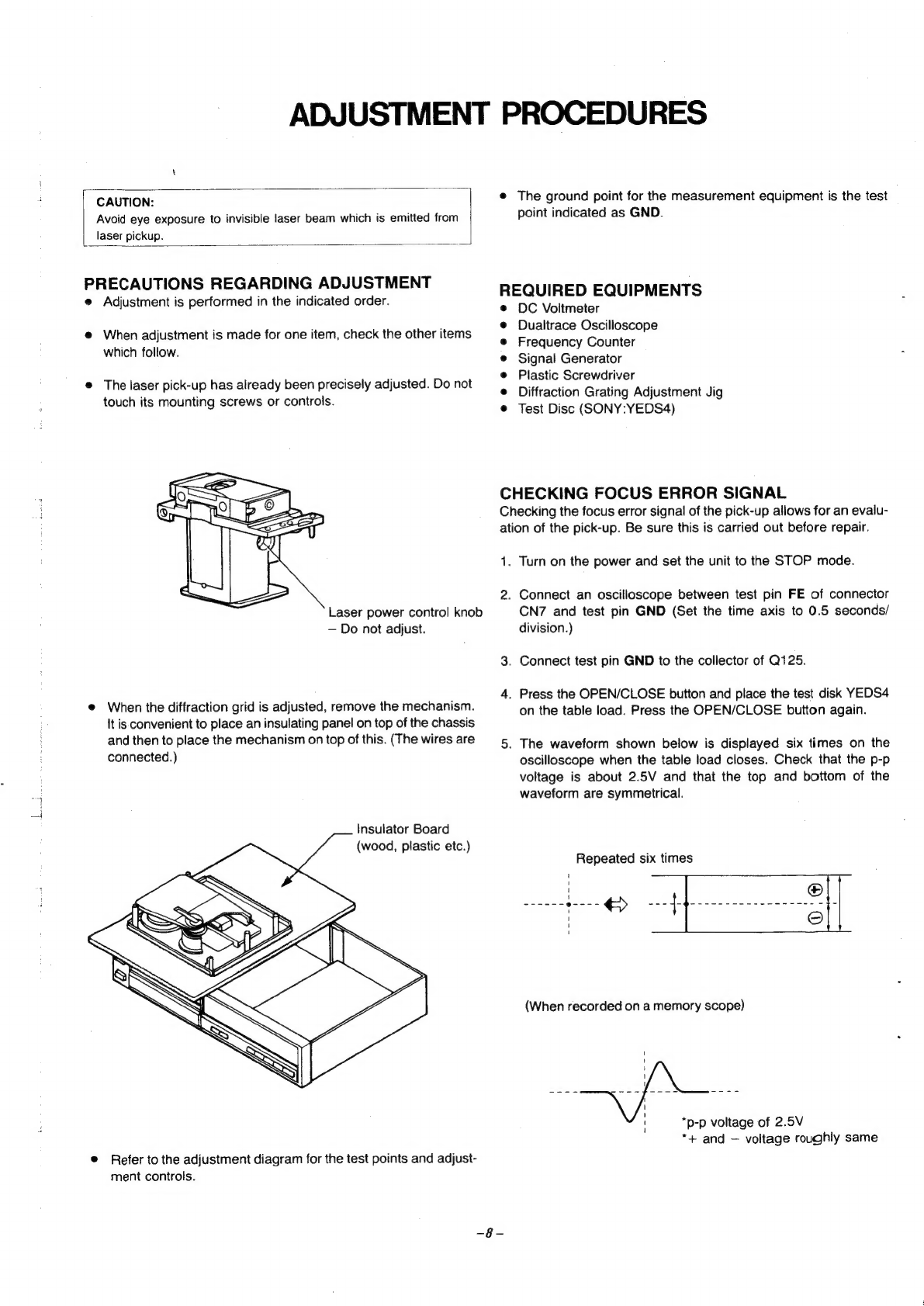
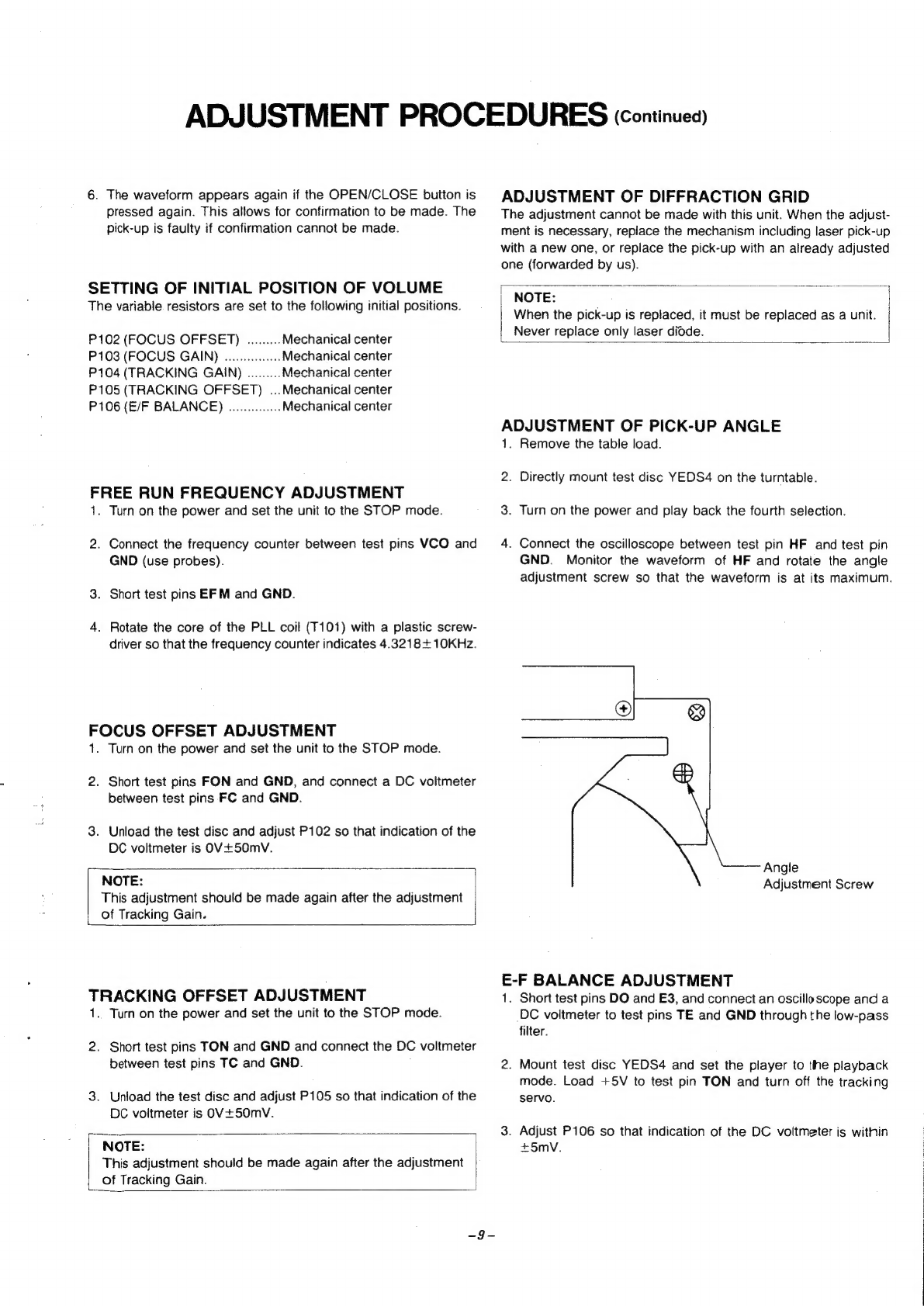
Teac PD-135 User manual

TEAC.
SERVICE
MANUAL
Compact
Disc
Player
COMPACT
olise
DIGITAL
AUDIO
Effective;
Octover
1987
5704037300

SPECIFICATIONS
System
Compact
disc
digital
audio
system
AUDIO
CHARACTERISTICS
Frequency
Response
5H2-20kHz,
+
1dB
Harmonic
Distortion
Less
than
0.007%
(1kHz)
S/W
Ratio
More
than
90dB
Wow
and
Flutter
Quartz
precision
Channel
Separation
More
than
80:B
(1kHz)
Output
Voltage
max.
2Vrms
FUNCTIONS
Instant
Program
Selection
Sequential,
with
MUSIC
SKIP
p>
pei
andid<
buttons
Index
Sequential,
with
SEARCH/INDEX
»
Pb
and
SEARCH/INDEX
<<
buttons
(Stop
mode
only)
Forward/back
Forward/back
with
sound
Program
Functions
16
selections
Repeat
All
selections
all
programmed
selections
Reset
Press
STOP
button
Pause
Each
selection
Disc
Loading
Motor
driven
horizontal
loading
DIGITAL
SIGNAL
PROCESSING
Optical
Pickup
3-beam
laser
Error
Correction
CIRC
Sampling
Frequency
44.1kHz
D/A
Conversion
16-bit
linear
Filter
Digital
filter
+
(4-pole
LC
filter)
GENERAL
Power
Source
120V,
BOHz
(U.S.A/CANADA)
220V,
50Hz
(EUROPE)
240V,
50Hz
(AUSTRALIA)
110/220V,
50/60Hz
(GENERAL
EXPORT)
9
Watts
Power
Consumption
Dimensions
(W
x
H
xD)
435
85.5
x
290mm
Weight
3.5kg

FUNCTIONAL
BLOCK
DIAGRAM
wor
¥SN3IdNOD
3SVHd
AS~
(WN)
¥OLOW
370NIaS
=
IANO
OD
ONINDVEL
rl
PETEeL,
[ese]
OUD
YORLNOD
NNBLSAS
HOLYSN3dNOD
3SVHd
wOIvYaNa9
HQUIMS,
TNS
TEA
D04
JOVILN
43L0dNOD
Cuow
2ONV
Ive
snoos
waNaHD
JOULNOD
OD
SIS
VHANIIG
BOL
VEvdsS:
3002-8NS
HOLIMS:
7OuLNOD
ONO
VEL
0193130
SSOWD
OUIZ
snoos
NOUDIOD
@NOLIILI0
2200
w4LH3ANOD
vO
;
Soto
~
WISABD
ed~10
Wes
ah
9019
0
woo
SNI04
WOD
ONIN
WHL
521
gl
1@
a
HOLYSN34NOD
'
to
3SVH
dv
43Sv7
cane)

SAFETY
CERTIFICATION
This
Compact
Disc
Player
is
made
and
tested
to
meet
exacting
safety
standards.
Laser
Diode
Properties
Material;
Ga-Al-As
Wavelength:
755-815nm
(25°C)
Laser
Output:
Continuous
Wave
max.
0.7mW
CAUTION
-
INVISIBLE
LASER
RADIATION
WHEN
OPEN
AND
INTERLOCKS
DEFEATED.
AVOID
EXPOSURE
TO
BEAM.
VORSICHT!
UNSICHTBARE
LASERSTRAHLUNG
TRITT
AUS
WENN
DECKEL
GEOFFNET
UND
WENN
SICHERHEITSVERRIEGELUNG
UBERBRUCKT
IST.
NICHT
DEM
STRAHL
AUSSETZEN!
\ARNING-
QSYNLIG
LASERSTRALNING
NAR
DENNA
DEL
AR
OPPNAD
OCH
SPARR
AR
URKOPPLAD.
STRALEN
AR
FARLKG.
ADVARSEL-
USYNLIG
LASERSTRALING
VED
ABNING.
NAR
SIKKERHEOSAFBRYDERE
ER
UDE
AF
FUNKTION.
UNDGA
UODSAETTELSE
FOR
STRALING.
CLASS
1
LASER
PRODUCT
CAUTION
—
USE
OF
CONTROLS
OR
ADJUSTMENTS
OR
PERFORMANCE
OF
PROCEDURES
OTHER
THAN
THOSE
SPECIFIED
HEREIN
MAY
RESULT
IN
HAZARDOUS
RADIATION
EXPOSURE.
THE
COMPACT
DISC
PLAYER
SHOULD
NOT
BE
ADJUSTED
OR
REPAIRED
BY
ANYONE
EXCEPT
QUALIFIED
SERVICE
PERSONNEL.
LASER
BEAM
RADIATION
SPOT
Optical
Pickup
Properties
Material:
Ga-Al-As
Wavelength:
790“um
Output
Power:
Max.
1.8mW
Radiant
Power:
Max.
8uW(Class_
I)
Laser
Beam
Radiation

CABINET
&
CHASSIS
EXPLODED
VIEW

EXPLODED
VIEW
-l
REF
.NO.
PARTS
NO.
CA
*9A00
765600
*9A0082
2300
CA
*9A00
766300
*9A0082
2900
CA
9A00
765800
9A0082
2500
CA
9A00
765900
9A0082
2600
CA
9A00
766000
9A0082
2700
CA
9A00
765700
9A00822400
CA
9A00
766100
9A0082
2800
CA
*9A00181500
9A00181700
*9A00179200
*9A00179800
*9A00169900
*9A001
70100
*9A00170200
*9A004
16400
*9A0
0442300
*9A00!
70500
*9A00
170600
*57605
18700
AN
*9A001
49600
A
*9A001
82200
*9A00
769700
*9A00182500
*9A00
182600
A
*576
1246800
A
*9A0
04
43300
A
*9A00767400
A
*9A00770100
9A00767500
9A00
769300
9A00769600
9A00770200
9A00769800
*9A00768500
*9A007685
10
*9A00
768700
*9A00768600
*9A00
767100
*9A00766700
*9A00
767000
*9A00171700
*9A00767200
*9A00181
400
*9A00
767300
(US]:U.S.A.
[A}]:AUSTRALIA
[C1:CANADA
DESCRIPTION
REMARKS
ESCUTCHEON
DIAL
ESCUTCHEON
DIAL
[SILVER]
DECORATE
PLATE
DIAL
DECORATE
PLATE
DIAL
[SILVER]
KNOB
EJECT
KNOB
EJECT
[SILVER]
KNOB
A
KNOB
A
[SILVER]
KNOB
B
KNOB
B
[SILVER]
KNOB
C
KNOB
C
[SILVER]
KNOB
POWER
KNOB
POWER
[SILVER]
PLATE
PAD
SWITCH
[GE]
SLIDE
SWITCH
3P
[GE]
COVER
SCREW
PAN
HD.TPG-B
M3X8
PLATE
BOTTOM
LEG
METAL
MOUNT
COVER
CHASSIS
MAIN
[US,C,E,A]
CHASSIS
MAIN
[GE]
SHAFT
CUSHION
RUBBER
SHAFT
BUSHING
[US,C,GE)
BUSHING
[E,A]
LUG
GROUND
[US,E]
MOUNT
PCB
[A]
SHEET
[A]
POWER
POWER
POWER
POWER
CORD
[GE]
CORD
[E]
CORD
[US,C}
CORD
[A]
POWER
POWER
POWER
POWER
TRANS
[US,C]
TRANS
[GE]
TRANS
[€]
TRANS
[AJ
C.
CERAMIC
0.022/50V
[US,E]}
MAIN
PCB
ASSY
[US,C]
MAIN
PCB
ASSY
[GE,E,A]
POWER
SWITCH
PCB
ASSY
CONTROL
PCB
ASSY
SCREW
SCREW
SCREW
SCREW
SCREW
S-TPG
BRZ
M3X8
S-TPG
BRZ
M3X8
S-TPG
BIN
M4xX10
TRANSIT
S-TPG
BRZ
M3X10
SCREW
SCREW
PAN
M3x8
[GE]
S-TPG
BRZ
M3X14
{GE]:GENERAL
EXPORT
[&]:EUROPE
Parts
marked
with
*require
fonger
delivery
time.

MECHANISM
EXPLODED
VIEW

EXPLODED
VIEW
-2
REF
NO.
PARTS
NO.
9A00567000
9A00171900
9A00172000
9A00172100
*9A001
72200
Ul
WN
—
*5
760707700
*9A00172300
9A00172600
*9A00172800
*9A001
73000
COON
D
VW
*9A00
767800
*9A00823
300
13
*9A00
173500
15
*9A00173700
16
*9A00
173800
*9A001
73900
9A00
174000
9A001
74100
9A00174200
9A00174300
9A00174
400
*9A00174500
*9A00
174600
*9A001
74700
*9A00
175300
*9A001
75400
*9A001
75500
*9A001
75600
9A00175700
*9A00175800
*9A00
175900
*9A001
76000
*9A001
76100
*9A001
76200
*9A00
1
76300
9A00823
100
*9A00767900
*9A00768000
*9A00
768
100
*9A00768200
*9A00768300
DESCRIPTION
PICK-UP
ASSY
LEAF
SWITCH
LEAF
SWITCH
MOTOR
CHASSIS
ASSY
GEAR
MOTOR
ASSY
SLIDE
BASE
PICK-UP
ASSY
T
LEVER
LOCK
ASSY
TABLE
LOAD
TABLE
LOAD
[SILVER]
HOLDER
DISK
SET
SCREW
V-CONE
2X4
SCREW
WASHER
PAD
DISK
TURNTABLE
GEAR
PINION
GEAR
PICK-UP
GEAR
LOAD
GEAR
CAM
SCREW
(B
TITE
SEMS)
SCREW
(B
TITE
SEMS)
Z
FLAP DISK
CRAMP
SLIDE
EJECT
LEVER
STOP
LEVER
HOLD
DISK
RIGHT
LEVER
HOLD
DISK
LEFT
SHAFT
PICK-UP
BALL
ROLLER
TABLE
SPRING
LEVER
SPRING
LEVER
SPRING
LEVER
SPRING
PLATE
SPRING
SLIDE
SPRING
LEVER
LOAD
RIGHT
LEFT
STOP
EJECT
LOCK
CD
MECHA
ASSY
86
SCREW
S-TPG
BIN
M2X6
SCREW
BIN
M2.
6X4
SCREW S-TPG
BRZ
M3X6
SCREW
PAN
PCS
M1.7X2.5
SCREW
PAN
PCS
MI.7X2
REMARKS
Z
INCLUDED
ACCESORIES
REF
.NO.
PARTS
NO.
*9A00768800
*9A0078
|
000
*9A00
768900
DESCRIPTION
REMARKS
OWNERS
MANUAL
[C,GE,E,A]
OWNERS
MANUAL
[US]
PLUG
CORD
{US1:U.S.A.
[C]:CANADA
[A]:AUSTRALIA
{GE]:GENERAL
EXPORT
[€]:EUROPE
Parts
marked
with
*require
longer
delivery
time.

ADJUSTMENT
PROCEDURES
CAUTION:
Avoid
eye
exposure
to
invisible
laser
beam
which
is
emitted
from
laser
pickup.
PRECAUTIONS
REGARDING
ADJUSTMENT
e
Adjustment
is
performed
in
the
indicated
order.
e@
When
adjustment
is
made
for
one
item,
check
the
other
items
which
follow.
@
The
laser
pick-up
has
already
been
precisely
adjusted.
Do
not
touch
its
mounting
screws
or
controls.
Laser
power
control
knob
—
Do
not
adjust.
@
When
the
diffraction
grid
is
adjusted,
remove
the
mechanism.
It
is
convenient
to
place
an
insulating
panel
on
top
of
the
chassis
and
then
to
place
the
mechanism
on
top
of
this.
(The
wires
are
connected.)
Insulator
Board
(wood,
plastic
etc.)
®
Refer
to
the
adjustment
diagram
for
the
test
points
and
adjust-
ment
controls.
The
ground
point
for
the
measurement
equipment
is
the
test
point
indicated
as
GND.
REQUIRED
EQUIPMENTS
DC
Voltmeter
Dualtrace
Oscilloscope
Frequency
Counter
Signal
Generator
Plastic
Screwdriver
Diffraction
Grating
Adjustment
Jig
Test
Disc
(SONY:YEDS4)
CHECKING
FOCUS
ERROR
SIGNAL
Checking
the
focus
error
signal
of
the
pick-up
allows
for
an
evalu-
ation
of
the
pick-up.
Be
sure
this
is
carried
out
before
repair.
1.
2.
Turn
on
the
power
and
set
the
unit
to
the
STOP
mode.
Connect
an
oscilloscope
between
test
pin
FE
of
connector
CN7
and
test
pin
GND
(Set
the
time
axis
to
0.5
seconds/
division.)
.
Connect
test
pin
GND
to
the
collector
of
Q125.
4.
Press
the
OPEN/CLOSE
button
and
place
the
test
disk
YEDS4
on
the
table
load.
Press
the
OPEN/CLOSE
button
again.
The
waveform
shown
below
is
displayed
six
times
on
the
oscilloscope
when
the
table
load
closes.
Check
that
the
p-p
voltage
is
about
2.5V
and
that
the
top
and
bottom
of
the
waveform
are
symmetrical.
Repeated
six
times
Hee
c@en
es
i 1
' '
' ' 4
1
1
1
1
1
1
1
1
i
1
4
‘
1 '
i 1
'
‘ t
'
‘
(When
recorded
on
a
memory
scope)
l
'
4
1
|
*p-p
voltage
of
2.5V
*+
and
—
voltage
roughly
same

ADJUSTMENT
PROCEDURES
(continuea)
6.
The
waveform
appears
again
if
the
OPEN/CLOSE
button
is
pressed
again.
This
allows
for
confirmation
to
be
made.
The
pick-up
is
faulty
if
confirmation
cannot
be
made.
SETTING
OF
INITIAL
POSITION
OF
VOLUME
The
variable
resistors
are
set
to
the
following
initial
positions.
P102
(FOCUS
OFFSET)
.........
Mechanica!
center
P103
(FOCUS
GAIN)
.............
Mechanical
center
P104
(TRACKING
GAIN)
.........
Mechanical
center
P105
(TRACKING
OFFSET)
...Mechanical
center
P106
(E/F
BALANCE)
..............
Mechanical
center
FREE
RUN
FREQUENCY
ADJUSTMENT
1.
Turn
on
the
power
and
set
the
unit
to
the
STOP
mode.
2.
Connect
the
frequency
counter
between
test
pins
VCO
and
GND
(use
probes).
3.
Short
test
pins
EFM
and
GND.
4.
Rotate
the
core
of
the
PLL
coil
(T101)
with
a
plastic
screw-
driver
so
that
the
frequency
counter
indicates
4.3218+
10KHz.
FOCUS
OFFSET
ADJUSTMENT
1.
Turn
on
the
power
and
set
the
unit
to
the
STOP
mode.
2.
Short
test
pins
FON
and
GND,
and
connect
a
DC
voltmeter
between
test
pins
FC
and
GND.
3.
Unload
the
test
disc
and
adjust
P102
so
that
indication
of
the
DC
voltmeter
is
OV+50mV.
NOTE:
This
adjustment
should
be
made
again
after
the
adjustment
of
Tracking
Gain.
TRACKING
OFFSET
ADJUSTMENT
1..
Turn
on
the
power
and
set
the
unit
to
the
STOP
mode.
2.
Short
test
pins
TON
and
GND
and
connect
the
DC
voltmeter
between
test
pins
TC
and
GND.
;
3.
Unload
the
test
disc
and
adjust
P105
so
that
indication
of
the
DC
voltmeter
is
OV+50mV.
NOTE:
This
adjustment
should
be
made
again
after
the
adjustment
of
Tracking
Gain.
ADJUSTMENT
OF
DIFFRACTION
GRID
The
adjustment
cannot
be
made
with
this
unit.
When
the
adjust-
ment
is
necessary,
replace
the
mechanism
including
laser
pick-up
with
a
new
one,
or
replace
the
pick-up
with
an
already
adjusted
one
(forwarded
by
us).
|
NOTE:
When
the
pick-up
is
replaced,
it
must
be
replaced
as
a
unit.
Never
replace
only
laser
didde.
ADJUSTMENT
OF
PICK-UP
ANGLE
1.
Remove
the
table
load.
2.
Directly
mount
test
disc
YEDS4
on
the
turntable.
3.
Turn
on
the
power
and
play
back
the
fourth
selection.
4.
Connect
the
oscilloscope
between
test
pin
HF
and
test
pin
GND.
Monitor
the
waveform
of
HF
and
rotate
the
angle
adjustment
screw
so
that
the
waveform
is
at
its
maximum.
Angle
Adjustment
Screw
E-F
BALANCE
ADJUSTMENT
1.
Short
test
pins
DO
and
E3,
and
connect
an
oscilloscope
and
a
DC
voltmeter
to
test
pins
TE
and
GND
through
the
low-pass
filter.
2.
Mount
test
disc
YEDS4
and
set
the
player
to
the
playback
mode.
Load
+5V
to
test
pin
TON
and
turn
off
the
tracking
servo.
3.
Adjust
P106
so
that
indication
of
the
DC
voltmeter
is
within
+5mvV.

ADJUSTMENT
PROCEDURES
ccontinuea)
22K
TE
:
22K
DC
©
Voltmeter
220/16
DC
Voltmeter
ms
and
GND
me
Oscilloscope
220/16
GND
Oscilloscope
3.
Turn
on
the
power
and
play
back
the
first
selection
on
test
disk
YEDS4.
4.
Readjust
the
height
of
the
turntable
if
the
reading
on
the
DC
CONFIRMING
JITTER
voltmeter
is
not
in
the
range
of
0V+0.35V.
(Increase:
the
This
procedure
can
be
omitted
in
the
case
that
no
jitter
counter
is
height
of
the
turntable
when
the
voltmeter
reading
is
positive,
equipped.
and
decrease
it
when
negative.)
1.
As
same
in
the
adjustment
of
the
pickup
angle,
play
the
fourth
tune
of
the
YEDS4.
2.
Connecting
the
jitter
counter
to
the
test
point
EFM,
make
sure
that
the
value
of
3T
is
less
than
25nSec.
ADJUSTMENT
OF
FOCUS/TRACKING
GAIN
The
measurement
circuit
shown
below
is
necessary
for
accurate
3.
In
the
case
of
25nSec
or
more,
adjust
again
the
Pick-up
Angle
adjustement
of
the
focus
and
tracking
gain.
If
this
circuit
cannot
and
adjust
P102.
be
made,
make
adjustments
using
the
simplified
procedure.
ADJUSTMENT
OF
TURNTABLE
HEIGHT
Simp
lededlustment
procedure
Thi
:
de'when
th
:
ides
@
Focus
gain
adjustment
is
adjustment
must
be
made
when
the
motor
is
replaced.
P103
is
set
to
a
position
30°
from
its
mechanical
center
as
shown
in
the
diagram
below.
30°
LLLLCLELLLALUUSLELLLLLELLLLLSLELLLLLUILLLELELEL
EET
LTTLLLEET
TTT
e@
Tracking
gain
adjustment
:
P104
is
set
to
a
position
30°
from
its
mechanical
center
as
shown
in
the
diagram
below.
2.
Connect
test
pin
FC
to
a
DC
voltmeter
and
oscilloscope
through
the
low-pass
filter.
30°
-19-
1.
Attach
the
turntable
so
that
its
top
surface
is
22.75mm
from
the
top
of
the
chassis.
22.75mm

6
Main
P.C.B.
:
CN2
“3
2
t
Tracking
Gain:
Focus
Gain}
~.
e4
6
ee
ae
Pick-up
CN2
3
2
1
ADJUSTMENT
PROCEDURES
ccontinuea)
5
Signal
Generator
10K
0047
—
10K
0.0047
i
Dualtrace
Oscilloscope
@
Remove
connector
CN2
from
the
pick-up
and
connect
the
measurement
circuit
between
the
PCB
and
pick-up.
e@
The
IC
used
is
TA7256P
e
VR
contro!
2k0-B
shorts
IN
and
SG,
1kHz
1Vp-p
is
supplied
from
the
signal
generator,
and
adjustment
is
made
for
minimum
output
from
OUT.
Precise
adjustment
procedure
1.
Focus
gain
adjustment
Connect
the
measurement
circuit
shown
above,
turn
on
the
power,
and
mount
the
test
disk
YEDS4.
Playback
the
first
selection
on
the
test
disk,
and
apply
a
950
Hz
0.5Vp-p
signal
from
the
signal
generator.
.
Observe
the
resurge
waveforms
on
the
oscilloscipe,
and
adjust
P103
so
that
the
phase
difference
of
outputs
X
and
Y
from
the
measurement
circuit
is
90°.
-/Jj-
Tracking
gain
adjustment
.
Adjustment
is
made
in
the
same
manner
as
for
focus
gain.
The
input
from
the
frequency
generator
is
set
to
950Hz
0.5Vp-p,
and
P104
is
adjusted
so
that
the
phase
difference
is
90°.

BOARD
ALIGNMENT
POINTS
Cc
p
EE
oy
ee
ae
ea
Sake
ae
~12-

SAFETY
INTERLOCK
The
Digital
Compact
Disc
Player
reads
the
disc
signal
by
'
detecting
the
laser
beam.
It
must
be
avoided
for
the
human
body
to
directly
receive
the
beam.
Especially
human
eyes
are
badly
affected
by
the
beam.
Therefore,
the
unit
is
equipped
with
an
interlock
to
prevent
the
unnecessary
laser
outputs.
The
laser
outputs
are
controlled
by
the
injection
or
cutoff
of
the
constant
voltage
source
to
the
laser
diode
with
Pin
23
of
IC
103
(LC6523H).
When
Pin
23
is
in
“L”
(Low)
level,
the
laser
emits
the
beam.
When
Pin
23
is in
“H”
(High)
level,
the
laser
does
not
emit
the
beam.
Pin
23
is
set
in
“H”
level
when
the
unit
is
loaded
with
the
disc
and
it
reads
the
index
signals
or
when
the
unit
is
set
in
the
play
mode
after
that.
When
the
unit
reads
the
index
signals
and
the
:
IC103
W103
LOADING
LIMIT
LC6523H
SWITCH
PLAY
SWITCH
~13-
following
two
conditions
are
met,
the
laser
emits
the
beam.
1)
When
the
Loading
Limit
Switch
is
set
in
“CLOSE”
side.
(The
disc
tray
is
closed.)
2)
The
pickup
is
located
at
the
area
of
the
minimum
internal
circumference.
After
the
above
conditions
are
met
and
the
index
signals
have
been
read,
the
laser
emits
the
beam
when
the
following
two
conditions
are
met.
1)
When
the
PLAY
button
is
pressed.
2)
When
the
PLAY
indicator
is
ON.
CONSTANT
VOLTAGE
POWER
SUPPLY
AUTOMATIC
LASER
POWER
CONTROL.
AC
POWER
SOURCE
D512
DISPLAY

NOTES:
|.
As
regards
the
resistors
and
capacitors,
refer
to
the
circuit
diagrams
and
the
PCB
ass'y
drawings
included
jin
this
brochure.
2.
Parts
marked
with
this
sign
are
safety
critical
cmponents.
They
must
always
be
replaced
with
Identical
components
-
refer
to
the
appropriate
parts
list
and
ensure
exact
replacement.
MAIN
PCB
ASSY
MAIN
PCB
ASSY
REF
.NO.
PARTS
NO.
DESCRIPTION
REFNO.
PARTS
NO.
DESCRIPTION
*9A00768500
MAIN
PCB
ASSY
{US,C]
9A00187900
PLUG
8P
*9A00768510
MAIN
PCB
ASSY
IGE,E,A]
9A00188000
PLUG
6P
*9A00770300
MAIN
PCB
9A00188100
PLUG
12P
DIOI,102
9A00774800
DIODE
GMAO|~-BT
9A00198000
CRYSTAL
DIi03,104
9GA00774900
DIODE
0S442-BT
9A00779200
CONNECTOR
IP
ASSY
DIO5-111
9A00774800
DIODE
GMAO|-BT
9A00780000
FUSE
T500MA
[GE,E,A]
DIt2
9A00774900
DIODE
DS442-BT
*¥9A00198400
FUSE
CLIP
DI
13
9A00775000
VARA.
DIODE
SVC2!
1SP
*9A00770400
COVER
SEVER’
DII4-117
9A00774800
DIODE
GMAO!-BT
*9A00770500
PLATE
HEAT
SINK
D118
9A00775100
ZENER
DIODE
GZA7.5X
*5
760526600
PLATE
HEAT
SINK
D119,120
9A00775200
ZENER
DIODE
GZA6.8X
*9A00183000
PIN
JACK
2P
DI21-124
9A00775300
DIODE
MPGO6B-G3
*5
761259300
WIRE
WRAP
TERMINAL
DI25
9A00775400
ZENER
DIODE
GZA2.4X-BT
1Cclol
9A00775600
IC
XC488A0
1C102
9A00775700
{C
YM3805
1C103
9A00775800
IC
LC6523H-3043
1C104,107
9A00775900
IC
NJM2068S-D
CONTROL
PCB
ASSY
1C105
9A00776000
IC
YM3015
1C106
9A00776100
IC
CXK5816M-}5L
REF
.NO.
PARTS
NO.
DESCRIPTION
1C108,109
9A00775900
IC
NJM2068S-D
*9A00768600
CONTROL
PCB
ASSY
1cl10
9A00776800
IC
7256P
*9A00779400
CONTROL
PCB
ICIII-
9A00776900
IC
L78M05
D501-508
9A00774900
DIODE
DS442-BT
ICL
t2
9A00777100
IC
L79MO5
D509
9400779600
LED
SLR-54MC3
Q101,102
9A00777500
TRANSISTOR
2SC536-F-NP
D510,51!
9A00779700
LED
SLR-54VC3
QI103,105
9A00777600
TRANSISTOR
2S01227-M
D512
9A00779800
LED
LB402DA
Q104,106
9A00777700
TRANSISTOR
2SB911-M
Q501,502
9A00778100
TRANSISTOR
2SB698-E
Q107,108
9A00777500
TRANSISTOR
2SC536-F-NP
$501-508
9A00438700
TACT
SWITCH
Qltl,!t2
9A00777500
TRANSISTOR
2SC536-F-NP
CN
6
9A00779500
CONECTOR
8P
ASSY
QI113,117
9A00777800
TRANSISTOR
2SA608-E-NP
CN
7
9A00780200
CONECTOR
I
IP
ASSY
Qi14,115
9A00777500
TRANSISTOR
2SC536-F-NP
QI16,1!18
9A00777900
TRANSISTOR
2SD734-E-K
QI19
9A00778000
TRANSISTOR
2SD612-E
.
Q120
9A00778100
TRANSISTOR
2SB698-E
QI21-125
9A00777500
TRANSISTOR
2SC536-F-NP
POWER
SWITCH
PCB
ASSY
C167,168
9A00774000
C.
ELEC
2200MF/16V
REFNO.
PARTS
NO.
DESCRIPTION
R216
9A00193400
R.
FUSEIBLE
10
1/2W
[US]
R216
9A00780100
R.
FUSEIBLE
4.7
|/4W
[GE]
*9A00768700
POWER
SWITCH
PCB
ASSY
R219,221
9A00193400
R.
FUSEIBLE
10
!/2W
[US]
*9A007
79900
POWER
PCB
R219,
22)
9A00780100
R.
FUSEIBLE
4.7
|/4W
[GE]
4\9A00201500
POWER
SWITCH
RBIOI
9A00779000
RM7
103J
ZX9A00201600
SPARK
KILLER
0.0
IMF/400V
*5760663000
EC
TERMINAL
IP
P1!02,105
9A00777300
POTENTIOMETER
20K(B)
P103,104
9A00777400
POTENTIOMETER
100K(B)
*5761259300
WIRE
WRAP
TERMINAL
P106
9A00777400
POTENTIOMETER
JOOK(B)
TIO1
9A00191500
COIL
OSC
T!102,103
9A00779100
AF
FILTER
{US]:U.S.A.
[C1]:CANADA
[IGE]:GENERAL
EXPORT
(€]:EUROPE
[AJ:AUSTRALIA
Parts
marked
with
require
longer
delivery
time.
~14-

MAIN
P.C.BOARD
(BOTTOM
VIEW)
~15-
—16-

POINT
TO
POINT
WIRING
DIAGRAM
EUROPE
POWER
TRANS
e
Fs
|
axed
6
&
Ee
.
}
\
&
:
|
co
—_
if
\
“Ss
‘
BK
RE
.
BK
:
a
OR
ee
OR
RE
:
MAIN
P.C.B.
AC220V
50Hz
POWER
PC.B.
Zz
toa
—
zur
i
conse
Gam
Gu
GmeD
cus
emo
Gum com
Game
comme
come
cm
om
cum
om
a
>
r
Bi
if
\
i
SW103
:
|
i
LOADING
i
i
LIMIT
\
|
SWITCH
|
PICK
UP
|
swi02
Peers
BH
|
‘Sr
ee
=
i
o(S(o[@
|
SWITCH
Gy
z
|
L
!
3
:
=
—
i]
a
|
—=oY
SR
i
I
RE
i
*BK=
|
|
BK=-@
BL
aut
1
i
a
|
BN
A
Se
SR
a
a
se
a
cee
aa
aac
a
ad
mMio2
~BK
SPINDLE
MOTOR
[O|
8
(=
|
:
i
f
:
M101
A
oe
LID
/
PICK
UP
HEAD
-
MOTOR
CONTROL
P.C.B.
77
=
—18-

U.S.A.
&
CANADA
POWER
TRANS
.
:
ahi
ge
oad
RE
BK
RE
AC120V
60Hz
AUSTRALIA
POWER
TRANS
©
:
ane
A
4
RE
BK
RE
AC240V
50Hz
GENERAL
EXPORT
VOLTAGE
SELECTOR
220V
110V
POWER
TRANS
®
FS
ax,
re,
et
GY:
RE
RK!
BK
OR
RE
AC220V/110V
50/60Hz
—79-

|e
ca
POWER
SWITCH
P.C.BOARD
(BOTTOM
VIEW)
F10084300
CONTROL
P.C.BOARD
(BOTTOM
VIEW)
-20-

IC
&
TRANSISTOR
LEAD
IDENTIFICATION
2SA608
2SB698
28C536
8
280734
1
28C3400
28D1012
NJM2068/FRONT/SIDE
VIEWS
28A937
TERMINAL
NAME
B—
BASE
Cc
—
COLLECTOR
——
EMITTER
NJM2068
BLOCK
DIAGRAM
y=
Table of contents
Other Teac CD Player manuals