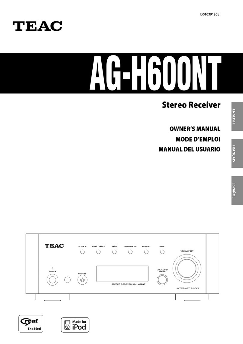
Teac AC-V8500 User manual

TEAC
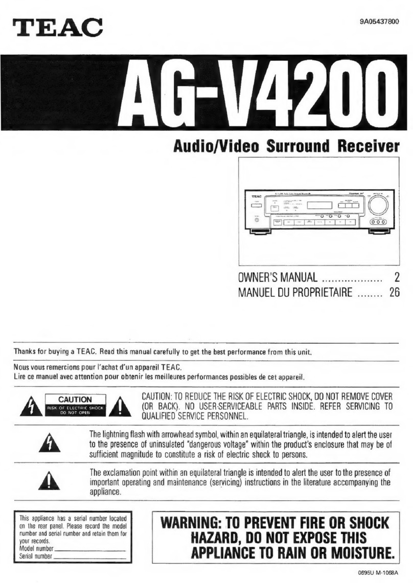
AG-V8500
Audio/Video
Surround
Receiver
Thanks
for
buying
a
TEAC.
Read
this
manual
carefully
to
get
the
best
performance
from
this
unit.
Nous
vous
remercions
pour
l’achat
d'un
appareil
TEAC.
Lire
ce
manuel
avec
attention
pour
obtenir
les
meilleures
perfor-mances
possibles
de
cet
appareil.
cmoooo
©oO0
Vielen
Dank
fiir
den
Kauf
dieses
TEAC-Gerats.
Bitte
lesen
Sie
diese
Anleitung
sorgfaltig
durch,
um
die
Leistungs-fahigkeit
dieses Gerats
optimal
nutzen
zu
kénnen.
FRANGAIS
ENGLISH
Grazie
per
aver
acquistato
un
prodotto
TEAC.
OWNERS
MANUAL
sciisicsssisinosississtesnisistie,
2
5
Leggere
attentamente
questo
manuale
per
ottenere
le
MANUEL
DU
PROPRIETAIRE
Peet
Soca
aan
teat
25
a
migliori
prestazioni
da
questo
apparecchio.
E
Enhorabuena
por
la
adquisicién
de
un
TEAC.
BEDIENUNGSANLEITUNG
DS
oa
as
48
ee
ee
a
fin
de
obtener
el
mejor
=
MIANUALE
DI
ISTRUZIONI
uu...
ec
eeecssseseeeen
1
££
MANUAL
DEL
USUARIO...
eesccssssssseeeeen
94
=
ot
oO
4
b
§
[o¥
‘f]
Ww
CAUTION:
TO
REDUCE
THE
RISK
OF
ELECTRIC
SHOCK,
DO
NOT
A
FISK
OPELec
Tan
scar
A
REMOVE
COVER
(OR
BACK).
NO
USER-SERVICEABLE
PARTS
INSIDE.
pO
vOL
OES
REFER
SERVICING
TO
QUALIFIED
SERVICE
PERSONNEL.
The
lightning
flash
with
arrowhead
symbol,
within
an
equilateral
triangle,
is
intended
to
alert
the
user
to
the
presence
of
uninsulated
“dangerous
voltage”
within
the
product’s
enclosure
that
may
be
of
sufficient
magnitude
to
constitute
a
risk
of
electric
shock
to
persons.
ence
of
important
operating
and
maintenance
(servicing)
instructions
in
the
literature
!
The
exclamation
point
within
an
equilateral
triangle
is
intended
to
alert
the
user
to
the
pres-
accompanying
the
appliance.
This
appliance
has
a
serial
number
located
on
the
rear
panel.
Please
record
the
model
number
and
serial
number
and
retain
them
WARNING:
TO
PREVENT
FIRE
OR
SHOCK
HAZARD,
DO
NOT
EXPOSE
THIS
APPLIANCE
TO
RAIN
OR
MOISTURE.
for
your
records.
Model
number
Serial
number

CONTENTS
PRECAUTIONS
.........ccscccssseessseeseeeessenesseessseesnecaneeeseeeaneneseanes
2
Read
This
Before
Operating...
csecesssssessneeeereeeeetteees
2
CONNECTIONS
uu...
cccccccscssesssccseeceeeedecsenssnsensesseseenenesenengees
3
System
Connections
....ccesccsceseeeseecenetenserereesseeneeceeseenes
3
Antenna
CONNECHIONS........ccescccceecseesserereveressereaneeeseresenees
4
Speaker
COMMections
.......scsessesscereeeetseetseessensceseenesessees
5
POW
COP
..eccccceeccrevssssseneccesensecscceceetsonecserursnssucvensenenensts
5
CONTROLS
AND
INDICATORG.
.........ccscccssesessseeenecerereenees
6
AUDIO
OPERATIONS
........ccccscsssecesesececenssonecseeseneesneenearenee
8
Basic
Operations
........sssssssseseceereeeseeeseeesneseseseeteeneens
8
Radio
RECEPtion
......sessssecssesessscsesesreeeensssserseseseasereneens
9
PreS@t
TUNING.
....cccsccscesseesseecesessereessesseasesenessnseeseeeseseenes
11
RDS
(Radio
data
SyStemM)
.......ccescecessesesssseesssreeeseeeeeee
12
Listening
to
Records
and
Compact
DISCS
..........s0
14
Playing
Tapes
.....scessssesssssesseseesectesereaseaateeeeesassaensenees
14
Recording
a
SOULCE.......seceeee
seu
cblesnPas¥ategestviubceneceucee
ees
14
VIDEO
OPERATIONS
.........:cccssccesececseeserssecssenrenseeernaeneaeees
15
Playing
VideO
SOUICES....ssceeseseetetetsetssetsesecesseeenenes
15
Recording
with
a
VideO
DeCK.......scesssecseereereeneneneees
15
SURROUND
EFFECTS
.....0......sccscscssceseeneessreenerernaensnnensenees
16
SUrrOUNd
MOES
.......csscccssseeeseessesssessesesseecessnseeeennensenees
16
Playing
Surround
SOUNG
.u..escecesseteseeeteaeeteseescnenens
18
MEMORY
BACKUP
FUNCTION
.........::cccssseserreeserseseneeeee
19
Back-Up
MeMOry..scisscccscssssssesserecsnecneeseesersatesestaaseneens
19
When
to
Use
Reset
SWItch........ccescssneseesssectrrerecenes
19
TEAC
SYSTEM
REMOTE-CONTROLLED
OPERATION.
.......c0cccccssrcsssssesscrsesseosceroneessccsscocenssensesssenonese
20
Using
a
CD
Player
and
a
Cassette
Deck
with
a
REMOTE SENSOR
Window......cccsccsessneeeeees
20
Buttons
for
the
Operation
of
Other
TEAC
COMPONENTS
.....ccsesscssesreserseeseeseeessenteeeneteeretsees
21
REMOTE
CONTROL
UNIT
...........cccccessssressenensesersseeneetenes
22
Using
the
Remote
Control
Unit
.....sccsessseerserereveees
22
TROUBLESHOOTING
.......cccesseessneseeeeeeenensnssnsassoneeessees
23
SPECIFICATIONS
........:cccescesseccssrseseeneresesseenenenseeenaneeesenens
24
PRECAUTIONS
Choose
the
installation
location
of
your
unit
carefully.
Avoid
placing
it
in
direct
sunlight
or
close
to
a
source
of
heat.
Also
avoid
locations
subject
to
vibrations
and
excessive
dust,
heat,
cold
or
moisture.
The
ventilation
holes
should
not
be
covered.
Make
sure
there
is
at
least
20
cm
(8
inches)
of
space
above
and
at
least
5
cm
(2
inches)
of
space
beside
the
amplifier/receiver.
Do
not
place
a
CD
player
or
other
equipment
on
top
of
the
amplifier/receiver.
Do
not
open
the
cabinet
as
this
might
result
in
damage
to
the
circuitry
or
electrical
shock.
Ifa
foreign
object
should
get
into
the
set,
contact
your
dealer.
When
removing
the
power
plug
from
the
wall
outlet,
always
pull
directly
on
the
plug,
never
yank
the
cord.
@
Do
not
attempt
to
clean
the
unit
with
chemical
solvents
as
this
might
damage
the
finish.
Use
a
clean,
dry
cloth.
Keep
this
manual
in
a
safe
place
for
future
reference.
IMPORTANT
(for
U.K.
Customers)
DO
NOT
cut
off
the
mains
plug
from
this
equipment.
lf
the
plug
fitted
is
not
suitable
for
the
power
points
in
your
home
or
the
cable
is
too
short
to
reach
a
power
point,
then
obtain
an
appropriate
safety
approved
extension
lead
or
consult
your
dealer.
If
nonetheless
the
mains
plug
is
cut
off,
remove
the
fuse
and
dispose
of
the
plug
immediately,
to
avoid
a
possible
shock
hazard
by
inadvertent
connection
to
the
mains
supply.
If
this
product
is
not
provided
with
a
mains
plug,
or
one
has
to
be
fitted,
then
follow
the
instructions
given
below:
IMPORTANT.
DO
NOT
make
any
connection
to
the
larger
terminal
which
is
marked
with
the
letter
E
or
by
the
safety
earth
symbol
+
or
coloured
GREEN
or
GREEN-and-YELLOW.
The
wires
in
the
mains
lead
on
this
product
are
coloured
in
accordance
with
the
following
code:
BLUE:
NEUTRAL
BROWN:
LIVE
As
these
colours
may
not
correspond
with
the
coloured
markings
identifying
the
terminals
in
your
plug
proceed
as
follows:
The
wire
which
is
coloured
BLUE
must
be
connected
to
the
terminal
which
is
marked
with
the
letter
N
or
coloured
BLACK.
The
wire
which
is
coloured
BROWN
must
be
connected
to
the
terminal
which
is
marked
with
the
letter
L
or
coloured
RED.
When
replacing
the
fuse
only
a
correctly
rated
approved
type
should
be
used
and
be
sure
to
re-fit
the
fuse
cover.
IF
iN
DOUBT
—
ELECTRICIAN.
CONSULT
A
COMPETENT

CONNECTIONS
ammennne
|
AUCIO
signal
mum
t
Video
signal
CAUTION:
Do
not
plug
the
power
cord
of
any
component
into
AC
outlets
and
do
not
turn
their
POWER
switches
on
until
all
connections
have
been
performed.
i
Refer
to
"Antenna
Connections"
on
pages
4-5.
TV
Monitor
Turntable
=
Tape
Deck
CD
Player
a
Des
*
5
5
6!
}
fo)
ge
w
wi
AC
Outlets:
uz!
< z
Two
switched,
Total
100W
MAX.
a0:
4
4
>3}
0
0
ne
oot
VIDEO
1—I-CD—DVD/VIDEO
3
DaASD
ats
VOLTAGEMFREQUENCY
‘SAME
AS AC
LINE
SST
Tee
ee
Cee
ee
me
|
t
4
r
So
ey
'
$
1
t
t
t
t
5
'
|
a
'
;
bt
_i5
'
'Z2!O
:
!
Stole
To
AC
outlet
'
mwa
2}
2;2
H
>
>3
ct
t
VIDEO1
“iy
i
g
'
t
_
be
512
0:9
Oo:
2
a
i
S
Rear
Speaker
Si
<
FrontB
FrontB
FrontA
Front
A
Speaker
Speaker
Speaker
Speaker
Audio
connection
cords
Center
Speaker
White
Witte
white
‘
L
©
NBS
pall
p>—©
L
R
@—
aati
\
ants
—-
p
t
Red
Red
Red

VIDEO
2
INPUT
Jacks
Video
Camera
Recorder,
etc.
FM
Indoor
Antenna
If
you
live
reasonably
close
to
a
transmitter
and
want
to
use
the
provided
lead-type
FM
antenna,
you
will
have
to
connect
it
direct
to
the
"FM
75Q"
socket.
Fit
the
metal
sleeve
of
the
lead-type
antenna
over
the
core
(center)
conductor
of
the
"FM
75Q"
socket,
extend
the
lead
and
fix
it
to
a
window
frame
or
wall
with
thumbtacks,
or
the
like,
where
reception
is
best.
(ey
Lead-type
FM
Antenna
(75
Q)
(provided)
|
FM
Outdoor
Antenna
|
In
an
area
where
FM
signals
are
weak,
it
will
be
necessary
to
use
a
75-ohm
unbalanced-type
outdoor
FM
antenna
using
the
optional
matching
transformer,
as
shown.
Generally,
a
3-element
antenna
will
be
sufficient;
if
you
live
in
an
area
where
the
FM
signals
i
are
particularly
weak,
it
may
be
necessary
to
use
one
with
5
or
more
elements.
Connect
the
coaxial
cable
of
the
antenna
to
the
match-
ing
transformer
as
shown.
After
completing
connection,
plug
the
transformer
into
the
"FM
75Q”
socket.
Outdoor
FM
Antenna
(75Q)
Matching
Transformer
(optional)
How
to
connect
a
coaxial
cable
to
the
matching
transformer
@
Strip
the
cable
and
dress
it
as
shown.
4mm
3mm
7mm
@
Press
both
side
tabs
outward
to
remove
the
cover.
@
Wrap
the
core
conductor
around
the
central
metal
fixture
as
shown.
Crimp
the
jagged
metal
fixtures
so
they
hold
the
braided
portion
using
pliers,
etc.
Put the
cover
back
in
place.
Jagged
metal
Insert
into
slit.
Jagged
metal

AM
(MW)
Antenna
MAM
Indoor
Loop
Antenna
A
high-performance
AM
loop
antenna
provided
with
the
receiver
is
sufficient
for
good
reception
in
most
areas.
Connect
the
loop
antenna’s
wires
to
the
AM
antenna
‘terminals
as
shown.
Place
the
antenna
on
a
shelf,
for
example,
or
hang
it
on
a
window
frame,
etc.,
in
the
direction
which
gives
the
best
reception,
as
far
away
as
’
possible
from
the
entire
system,
speaker
cords
and
the
power
cord,
to
prevent
unwanted
noise.
M@
AM
Outdoor
Antenna
If
the
AM
loop
antenna
provided
does
not
deliver
sufficient
reception
(because
you
are
too
far
from
the
transmitter
or
in
a
concrete
building,
etc.),
it
may
be
necessary
to
use
an
outdoor
AM
antenna.
Use
an
insulated
wire
more
than
15
ft
(5
m)
long,
strip
one
end,
and
connect
this
to
the
terminal
as
shown.
The
antenna
wire
should
be
strung
outdoors
or
indoors
near
a
window.
For
better
reception,
connect
the
GND
terminal
to
a
reliable
ground.
Note:
Even
when
using
an
outdoor
AM
antenna,
do
not
disconnect
the
AM
loop
antenna.
AM
Outdoor
Antenna
AM
Loop
Antenna
(provided)
Caution:
To
avoid
damaging
the
speakers
by
inputting
a
sudden
high-level
signal,
be
sure
to
switch
the
power
off
before
connecting
the
speakers.
Connect
each
speaker
to
the
corresponding
speaker
terminals,
as
desired.
For
"Speaker
Installation",
refer
to
page
17.
Notes:
@
When
using
the
rear
speakers,
be
sure
to
connect
them
to
both
channels
(L
and
R).
If
a
speaker
is
con-
nected
to
only
one
channel,
no
sound
will
be
heard.
e
Use
speakers
with
a
nominal
impedance
of
8
ohms
or
more.
How
to
connect
the
speaker
cords
Press
the
lever,
insert
the
stripped
and
twisted
end
(approx.
10
mm)
of
the
cord,
then
release
the
lever
so
that
the
cord
is
held
securely.
Be
sure
to
connect
the
power
cord
to
an
AC
outlet
which
supplies
the
correct
voltage,
as
set
by
the
voltage
selector.
AC
OUTLETS
SWITCHED:
This
socket
switches
on
and
off
as
you
turn
on
and
off
the
amplifier.
Caution:
The
total
power
consumption
of
the
components
con-
nected
to
the
AC
OUTLETS
must
not
exceed
100W.
ENGLISH

CONTROLS
AND
INDICATORS
i
Front
Panel
Dm
Ww 16
17
bOLDa
@
24
25
DiGrro-
—
TIMER
omen
i
coe
Om)
|
asst
il
TAT
Ai
I
INA
fat
Aa
ha)
A A
“i
4
“vorwirpaanro
UA
IAN
JAN
AN
JAN
JASE
JAN
JAN
ee
CF
I
ns

Hi
Remote
Control
Unit
,
@-
i
DVD/
VIDEO
1
VIDEO
2
VIDEO
3)
MEMORY
DIRECT
:
vy)
SCAN
TUNING
SAND/“_
PRESET
CALL.
26
4
fa
Ce
a
‘
8
27
.
a
PLAY
4
Q)
PLAY
17
x
RROUND
CENTER
DELAY
TEST
:
(4)
QDE
MODE
TIME
TONE
(4)
elt)
23
24
12
ut)
TEAC
REMOTE
CONTROL
UNIT
GTR
Certain
buttons
on
the
remote
control
unit
and
on
the
front
panel
of
the
receiver
have
the
same
or
similar
*
functions
and
have
the
same
reference
numbers.
@
The
power
is
turned
on/off
(standby)
by
pressing
the
POWER
button
on the
remote
control
unit
in
standby
mode.
@
Main
POWER
Switch
and
STANDBY/ON
Button
@
LINE
STRAIGHT
Button
©
Source
Selector
Buttons
@
REMOTE SENSOR
Window
©
Numeric
Keys
@
Multi-Function
Display
@
MEMORY
Button
©
TUNING
/PRESET
Buttons
©
MODE
Button
@®
BASS
and
TREBLE
Controls
@
LOUDNESS
Button
@
MASTER
VOLUME
Control
(VOLUME
+/-
Buttons)
@®
BALANCE
Control
@
PHONES
Jack
@
RDS
MODE
Button
@
SPEAKERS
Select
Buttons
@
SURROUND
MODE
Buttons
@
CENTER
MODE
Button
@
DELAY
TIME
Button
@
FM
MODE
Button
@
TEST
TONE
Button
@®
BAND
Selector
Button
@
CENTER
LEVEL
DOWN/UP
Buttons
@
REAR
LEVEL
DOWN/UP
Buttons
@
VIDEO
2
iNPUT
Jacks
@
MEMORY
SCAN
Button
@&
DIRECT
TUNING
Button
@
TAPE
Deck
Operation
Buttons
@
CD
Player
Operation
Buttons
€
MUTING
Button
@
SLEEP
Button
Ea
CENTER
MODE
Indicators
fa
SURROUND
MODE
Indicators
Ei
TIMER
Indicator
Gi
TUNED
Indicator
Ei
STEREO
Indicator
f
RDS
MODE
Indicator
TAPE
Monitor
Indicator
El
MEMORY
Indicator
—i
BAND/FREQUENCY
Display
@
Source
Display
fl
PRESET
Channel
Display
fd
SLEEP
Time
Display
fk)
DELAY
Time
Display
Hi
TEST
TONE
Display
fi
CENTER
LEVEL
Display
i
REAR
LEVEL
Display
ENGLISH

AUDIO
OPERATIONS
Note:
The
following
points
apply
throughout
the
"AUDIO
and
VIDEO
OPERATIONS”
sections
unless
otherwise
noted.
@
To
simplify
explanations,
instructions
refer
to
names
of
buttons
and
controls
on
the
front
panel,
making
no
mention
of
the
use
of
remote
control
unit.
®
To
listen
to
a
source
other
than
tape
deck,
press
the
TAPE
MONITOR
button
to
the
OFF
position
(the
TAPE
monitor
indicator
will
not
light
in
the
display).
SLEEP
Timer
Function
This
function
allows
you
to
preprogram
the
receiver
to
switch
its
own
power
off
automatically.
You
can
then
enjoy
the
audio/video
system
for
a
specified
amount
of
time
without
having
to
worry
about
turning
the
unit
off
later.
Each
press
of
the
SLEEP
button
changes
the
time
indication
by
10
minutes.
["
SLEEP
90
~>
SLEEP
80
—
---
->
SLEEP
a
(Released
condition)
To
let
the
remaining
time
(until
power
off)
appear
on
the
display
while
the
sleep
timer
is
engaged,
press
the
SLEEP
button
once.
|
1.
Set
the
MASTER
VOLUME
control
to
''0''.
This
is
to
protect
the
speakers
from
a
sudden
high-level
signal.
2.
Set
the
LOUDNESS
button
to
the
OFF
position.
3.
Adjust
the
tone
as
required
with
the
BASS
and
TREBLE
tone
controls.
Adjust
the
balance
between
the
left
and
right
channels
with
the
BALANCE
control.
4.
Press
the
POWER
button
to
ON.
5.
Select
the
desired
source
with
the
source
selector
buttons.
6.
Press
the
BYPASS
button
to
set
the
surround
mode
to
OFF.
7.
Select
the
speaker
system
to
be
used
with
the.
SPEAKERS
select
buttons.
8.
Start
playing
the
source
component.
9.
Gradually
turn
up
the
volume
to
the
required
level
with
the
MASTER
VOLUME
control.
Mf
Private
listening
For
private
listening,
insert
the
headphones
(1/4-inch
plug)
into
the
PHONES
jack.

Audio
Adjustments
POWER
ON
LINE
STRAIGHT
BASS/TREBLE
SPEAKERS
LOUDNESS
BALANCE
Main
POWER
switch
and
STANDBY/ON
Button
When
the
main
POWER
switch
is
ON:
Press
STANDBY/ON
button
to
turn
the
power
on.
Press
it
again
to
turn
the
system
off
(power
standby
mode).
The
indicator
lights
up
in
power
standby
mode
and
goes
out
when
this
unit
is
turned
on.
SPEAKERS
Select
Buttons
These
buttons
are
used
to
select
speaker
system
A
or
B.
LINE
STRAIGHT
Button
When
this
button
is
pressed,
the
signal
selected
by
the
source
selector
buttons
is
supplied
directly
to
the
amplifier
circuit,
allowing
you
to
listen
to
tt
e
source
with
better
sound
quality.
When
the
LINE
STRAIGHT
mode
is
selected,
the
BASS,
TREBLE
controls
will
be
defeated.
BASS/TREBLE
Tone
Controls
These
two
tone
controls
—
BASS
and
TREBLE
—
can
be
used
to
obtain
a
"flat"
frequency
response
or
a
tone
which
suits
your
individual
listening
preference.
The
Bass
control
adjusts
low
frequencies
and
the
TREBLE
control
adjusts
the
high
frequencies.
BALANCE
Control
This
control
is
used
to
adjust
the
balance
between
the
left
and
right
channels.
Normally
set
to
the
center
position.
LOUDNESS
Button
-
This
button
compensates
for
the
non-linear
response
of
the
human
ear
at
low
volumes.
Set
this
switch
to
the
OFF
position
when
listening
at
normal
levels.
MUTING
Button
(on
the
Remote
Control
Unit)
Press
this
to
mute
(-20
dB)
the
sound
from
the
speak-
ers
and
headphones
when
answering
the
telephone,
etc.
To
restore
the
original
volume,
press
the
MUTING
button
again.
While
muting
is
engaged,
the
MASTER
VOLUME
level
indicator
will
flicker.
POWER
ON
.
Press
the
TUNER
button*.
*
The
TUNER
button
can
also
be
pressed
instead
when
you
want
to
listen
to
a
station
selected
last
by
changing
from
another
source.
.
Select
the
AM
or
FM
by
pressing
the
BAND
selector
button.
.
Press
the
MODE
button
to
change
to
TUNING
mode.
(The
PRESET
CH.
indicator
disappears
from
the
display).
This
button
is
used
to
select
Tuning
or
Preset
scan
mode.
.
Press
the
UP
or
DOWN
TUNING
button
(within
0.5
to
2
seconds).
The
next
station
broadcasting
at
a
frequency
higher
or
lower
than
that
of
the
current
station
is
automatically
detected
and
tuned
in.
By
pressing
and
holding
the
TUNING
button
for
longer
than
2
seconds,
it
will
continue
to
control
(three
times
faster
than
normal
speed).
e
FM
MODE
Button
Pressing
this
button
alternates
between
Stereo
mode
and
Mono
mode.
Stereo
FM
stereo
broadcasts
are
received
in
stereo
and
the
STEREO
indicator
lights
in
the
display.
Monophonic
broadcasts
are
received
in
mono.
lf
FM
broadcasts
with
weak
signal
strength
are
received,
the
FM
muting
(-20
dB)
function
works
automatically
to
cut
the
signals,
eliminating
loud
noise.
Mono
To
compensate
for
weak
FM
stereo
reception,
select
this
mode.
Reception
will
now
be
forced
monaural,
reducing
unwanted
noise.
TUNED
Indicator
“TUNED"
appears
in
the
display
when
a
broad-
cast
is
correctly
tuned
in.

[
Manual
Tuning
=
Manual
Tuning
is
generally
used
to
tune
to
stations
broadcasting
a
signal
that
is
too
weak
to
be
received
by
Auto
Tuning.
1.
Press
the
TUNER
button.
2.
Select
the
AM
or
FM
by
pressing
the
BAND
selector
button.
.
Press
the
MODE
button
to
change
to
TUNING
mode.
(The
PRESET
CH.
indicator
disappears
from
the
display).
.
When
the
UP
or
DOWN
TUNING
button
is
pressed
momentarily
(0.5
second
or
less),
the
frequency
changes
by
a
fixed
step
(see
STEPS
below).
STEPS
FM:
50-kHz
steps
AM:
9-kHz
steps
Direct
Tuning
Using
this
method,
the
required
frequency
is
input
directly,
using
the
numeric
keys.
Rewore
contron
unit
HER
—~10—-
4,
.
Press
the
TUNER
button.
.
Select
the
AM
or
FM
by
pressing
the
BAND
selector
button.
.
Press
the
DIRECT
TUNING
button
on
the
remote
control
unit,
"ENTER
FREQUENCY"
appears
on
the
display
for
a
few
seconds.
"FM
display.
MHz"
or
"AM----kHz"
appears
on
the
Input
the
frequency
of
the
broadcast
you
want
to
hear
with
the
numeric
keys.
If
you
press
the
DIRECT
TUNING
button
again
or
without
pressing
any
button
for
30
seconds,
Direct
tuning
is
released.
FM:
50-kHz
steps
AM:
9-kHz
steps
Ex.:
FM
107.55
MHz

This
facility
is
used
to
store
FM,
AM
broadcasting
from
Channel
1
to
30
respectively.
|
Automatic
Memory
Presetting
1.
Press
the
TUNER
button.
2.
Select
the
AM
or
FM
by
pressing
the
BAND
selector
button.
3.
Press
the
MEMORY
button
for
a
while
(for
more
than
1.5
seconds).
The
start
frequency
will
show
in
the
display.
e
87.5
MHz
in
FM,
522 kHz
in
AM.
The
frequency
and
display
will
automatically
scan.
'
e
50
kHz
steps
for
FM,
9
kHz
steps
for
AM.
Ei
The
frequency
shown
in
the
display
will
rapidly
change.
As
each
station
is
located
a
preset
number
will
appear
in
the
display
indicating
which
preset
MEMORY
button
has
been
assigned
to
the
station
located.
The
scanning
process
will
contin-
ue
to
operate
in
this
fashion
until
30
stations
have
been
found
and
entered
into
the
preset
memory
or
when
there
are
no
more
stations
to
be
found
on
the
waveband
chosen.
The
memory
indicator
will
extinguish
and
let
you
hear
the
last
station
to
be
memorized.
To
listen
to
the
memorized
station
select
the
band
required
and
press
the
numeric
keys
button
1,
2,
3
etc.
4.
The
last
memorized
channel
of
each
band
will
be
displayed
when
Auto
Memory
is
completed.
Check
the
programmed
frequencies
with
PRESET
UP,
DOWN
button.
Tp
|
Manual
Memory
Presetting
POWER
ON
6
15463
2
.
Press
the
TUNER
button.
.
Select
the
AM
or
FM
by
pressing
the
BAND
selector
button.
:
.
Press
the
MODE
button
to
change
to
TUNING
mode.
(The
PRESET
CH.
indicator
disappears
from
the
display).
.
Select
the
frequency
you
want
to
preset
by
pressing
UP
or
DOWN
tuning
button.
.
Press
the
MEMORY
button
briefly,
MEMORY
display
will
blink
at
an
interval
of
1
second.
.
While
the
MEMORY
indicator
is
lit,
press
the
numeric
key(s)
to
input
the
channel
number
in
which
the
data
(AM
or
FM
band
and
frequency)
for
the
broadcast
is
to
be
stored
(or
press
the
PRESET
button
then
press
the
MEMORY
button
again).
i
Recalling
Frequencies
.
Press
the
numeric
key(s)
corresponding
to
the
channel
number
to
tune
directly
to
a
broadcast.
Mi
Using
the
Memory
Scan
function
When
the
MEMORY
SCAN
button
is
pressed,
the
preset
channels
in
which
frequencies
in
the
band
(AM
or
FM)
selected
have
been
stored
are
scanned
at
5-second
intervals.
When
you
hear
a
broadcast
you
want
to
listen
to,
release
the
Memory
Scan
function
by
pressing
the
MEMORY
SCAN
button
again.
@
"Back-up"
memory
function
This
function
conserves
the
already
preset
station
mem-
ories,
and
"Most-recent"
memory
function,
even
in
the
event
of
a
cut-off
of
power
supply,
as
when
the
plug
is
pulled
out
of
the
wall
outlet,
for
3
days.

RDS
is
a
broadcasting
service
which
allows
stations
to
send
additional
information
along
with
the
regular
radio
program
signal
RDS
services
can
be
received
only
in
FM
band.
,
RDS
Display
POWERON
4
1,
Press
the
TUNER
button.
2.
Press
the
BAND
button
to
select
FM.
.
3.
Select
the
RDS
broadcasting by
use
of
the
MODE
button
and
the
TUNING/PRESET
buttons.
@
The
RDS
indicator
lights
in
the
display.
This
unit
receives
and
displays
the
following
kinds
of
data.
e@
PS
(Program
Service
Name):
Displays
FM
station
name.
@
PTY
(Program
Type):
Program
type
will
be
displayed
while
receiving
FM.
@
RT
(Radio
Text):
Displays
the
news
of
stations
com-
posed
of
up
to
64
symbols.
@
CT
(Clock
Time):
Displays
the
information
about
times
provided
from
the
station.
e@
TP
(Traffic
Program)
@
TA
(Traffic
Announcement)
4.
Press
the
RDS
MODE
button.
Each
time
you
press
the
button
briefly
(1.5
sec
or
less),
the
modes
will
change
as
follows
regardless
of
the
current
mode.
Pern
ee
ent
e
a
BP>
on
(1)
PS
mode
@
When
you
select
PS
with
the
RDS
MODE
button,
"PS"
will
blink
for
about
4
seconds.
e@
After
4
seconds,
PS
or
a
station
name
will
be
displayed.
={2—
(2)
CT
mode
@
When
you
select
CT
with
the
RDS
MODE
button,
"CT"
will
blink
for
about
4
seconds.
After
4
seconds,
the
clock
time
will
be
displayed.
e
If
there
is
no
CT
data
among
received
broadcastings,
"NO
CT"
will
be
displayed.
(3)
PTY
mode
@
When
you
select
PTY
with
the
RDS
MODE
button,
PTY
will
blink
for
about
4
seconds.
After
4
seconds,
the
type
of
received
PTY
will
be
displayed.
There
are
31
kinds
of
PTY
Data
as
follows.
brief
annoucements,
events,
public
opinion,
reports,
actual
situations.
AFFAIRS
|
@
kind
of
suggestion
including
practical
annoucements
other
than
news,
documents,
discussion,
analysis
and
so
on.
INFO
|
daily
information
or
reference
such
as
weather
forecast,
consumer
guide,
medical
|
assistance
and
so
on.
sports-related
programs.
educational
and
cultural
information.
all
kinds
of
radio
concert
and
serial
drama.
all
aspects
of
national
or
local
culture
includ-
ing
religious
events,
philosophy,
social
science,
language,
theatre,
and
so
on.
SCIENCE
|
programs
on
natural
science
and
technology.
VARIED
|
Popular
programs
such
as
quiz,
entertain-
ment,
private
interview,
comedy,
satire
and
so
on.
program
on
commercial,
practical
and
popu-
lar
songs,
and
sale
volume
of
discs,
etc.
ROCK
M
|
Practical
modern
music
generally
composed
and
played
by
young
musicians.
M.O.R.M
|
Popular
music
usually
lasting
for
less
than
5
minutes.
LIGHT
M
|
Classical
music,
instrumental
music,
chorus,
and
light
music
favoured
by
non-profession-
als.
[CLASSICS
orchestra
including
great
operas,
symphony,
chamber
music
and
so
on.
OTHER
M
|
Other
music
styles
(Rhythm
&
Blues,
Reggae,
etc.)
[WEATHER
weather
reports,
forecast
FINANCE
|
financial
reports,
commerce,
trading

children’s
programs
social
affairs
religious
programs
program
in
which
the
public
expresses
its
view
by
phone
travel
reports
|
areacaite
concerning
recreational
activities
jazz
music
country
music
national
music
music
from
the
so-called
golden
of
popular
music
folk
music
documentaries
(ACARI
this
is
a
program
notifying
an
emergency
or
a
natural
disaster.
@
If
there
is
no
PTY
data
among
received
broadcast-
ings,
RDS
mode
will
be
switched
to
PS
mode
auto-
matically.
(4)
RT
mode
@
When
you
select
RT
with
the
RDS
MODE
button,
"RT"
will
blink
for
about
4
seconds.
After
4
seconds,
the
data
of
received
RT
will
be
displayed.
®
|f
there
is
no
RT
data
among
received
broadcastings,
RDS
mode
will
be
automatically
switched
to
PS
mode.
(5)
TA
mode
(TP
Search
Function)
@
When
you
select
TA
by
use
of
the
RDS
MODE
button,
"TA"
will
blink
for
about
4
seconds.
After
4
seconds,
TP
received
broadcasting
will
be
searched
with
FM
frequency
increasing
in
50
kHz
steps.
If
TP
received
broadcasting
is
searched,
the
increase
in
frequency
will
stop
and
it
is
asked
whether
TA
will
be
received
or
not.
if
TP
and
TA
turn
off
while
you
are
receiving
TA,
the
tuner
will
search
TA
broadcasting
again
with
FM
fre-
quency
increasing
in
50
kHz
steps.
413%:
How
to
Search
For
Your
Desired
Program
Using
PTY
Search
_
id
wo
S
.
Press
the
TUNER
button.
.
Press
the
MEMORY
button.
POWERON
3
1546
2
ENGLISH
.
Press
the
BAND
button
to
select
FM.
.
Press
the
RDS
MODE
button
for
longer
than
1.5
seconds.
Then
"PTY
SEEK"
will
be
shown
in
the
display.
.
Select
the
desired
PTY
mode
by
using
the
TUNING/PRESET
(\“/A)
buttons.
Select
your
desired
one
from
among
31
kinds
of
PTY
programs.
(The
program
will
blink.)
The
program
indicator
is
changed
to
light
steadily.
(
.
Press
the
TUNING/PRESET
UP
(A)
or
DOWN
(v)
button.
(Searching
will
start.)
When
the
PTY
mode
that
you
have
selected
is
searched,
searching
will
stop
and
the
PTY
mode
will
be
displayed.
When
you
press
the
TUNING/PRESET
(\“/A)
buttons
after
your
desired
program
is
searched,
you
can
continue
to
search
for
the
same
program
type
by
increasing
or
decreasing
the
frequency
from
the
cur-
rent
one.
If
the
same
program
type
is
not
found
during
PTY
Search,
it
will
stop
at
the
beginning
frequency.
lf
you
want
to
cancel
PTY
search
while
searching,
press
the
RDS
MODE
button.
Searching
will
stop
and
search
mode
will
be
released
automatically.

ro
ON
1
=,
(eer
JOG
0
Seer
ire
Turntable
or
CD
Player
1.
Press
the
PHONO
or
CD
button.
2.
Play
the
turntable
(with
a
moving
magnet
cartridge)
or
CD
player.
000
3
&
5
Tape
Deck
1.
Set
the
TAPE
MONITOR
button
to
ON;
the
TAPE
monitor
indicator
will
appear
in
the
display.
2.
Operate
tape
deck
for
playback.
~14—
Recording
program
source
you
can
record
a
program
source
such
as
a
record
or
Compact
Disc
onto
a
cassette
deck
connected
to
the
TAPE
REC
jacks.
POWER
ON
Source
component
1.
Make
sure
the
TAPE
MONITOR
button
is
set
to
OFF,
then
press
the
source
selector
button
corresponding
to
the
source
to
be
recorded.
2.
Play
the
source.
3.
Operate
the
tape
deck
for
recording.
Hi
Tape
Monitoring
If
the
tape
deck
has
separate
record
and
playback
heads,
during
recording,
the
recorded
sound
can
be
heard
from
the
speakers
with
the
TAPE
MONITOR
button
set
to
ON.

VIDEO
OPERATIONS
Note:
For
playing
video
software
using
a
certain
Surround
Effect
function,
refer
to
the
SURROUND
EFFECTS
section.
POWER
ON
cK,
:
Video
signals
ma.
:
Audio
signals
VIDEO
1
DVD/VIDEO
3
Speakers
1.
Press
the
VIDEO
1,
VIDEO
2
or
DVD/VIDEO
3
button.
2.
Play
the
component
corresponding
to
the
button
pressed.
3.
The
picture
from
the
video
source
can
be
seen
on
the
TV
and
the
sound
from
the
video
source
will
be
heard
from
the
speakers.
‘signal
dubbing.
-~15-—
Tape
Dubbing
(from
VIDEO
2
to
VIDEO
1)
POWER
ON
c\
:
Video
signals
ma.
:
Audio
signals
VIDEO
1
DVD/VIDEO
3
VIDEO
2
Recording
Playback
Playback
1.
Press
the
VIDEO
2
or
DVD/VIDEO
3
button
with
the
TAPE
MONITOR
set
to
OFF.
2.
Operate
VIDEO
2
or
DVD/VIDEO
3
for
playback.
3.
Operate
VIDEO
1
for
recording.
In
this
way,
the
video/audio
signals
from
VIDEO
2
or
DVD/VIDEO
3
can
be
dubbed
onto
VIDEO
1.
S.A.V.E.
(Second
Audio
Source
for
Video
Editing)
SYSTEM
Function
This
feature
lets
you
replace
the
sound
from
a
VCR
with
sound
from
an
AUDIO
source
such
as
CD
during
video
1.
Press
the
DVD/VIDEO
3
(or
VIDEO
2)
button
and
operate
DVD
or
VIDEO
3
(or
VIDEO
2)
for
playback.
2.
Select
the
audio
source
with
the
source
selector
buttons,
and
then
operate
the
selected
audio
com-
ponent
for
playback.
3.
Now
you
can
watch
the
picture
from
the
video
com-
ponent
on
the
TV,
and
listen
to
the
sound
from
the
audio
component
through
the
speakers.
Note:
Be
sure
to
observe
the
order
of
steps
1
and
2.
4.
Operate
VIDEO
1
for
recording.
In
this
way,
the
S.A.V.E.
operation
will
be
completed.

SURROUND
EFFECTS
When
you
use
the
surround
function,
the
sound
creates
a
“live”
atmosphere
such
as
that
experienced
in
movie
theaters
and
concert
halls.
This
unit
is
provided
with
the
following
surround
modes,
which
can
be
selected
using
the
SURROUND
MODE
switches.
Select
the
appropriate
surround
mode
according
to
the
program
source.
DOLBY
PRO
LOGIC
Surround
Use
this
mode
when.playing
movie
or
music
video,
soft-
ware
which
carries
the
D0
DOLBY
SURROUND
mark.
This
mode
provides
the
effect
of
being
in
a
movie
theater
or
live
concert
house-an
effect
with
an
intensity
which
can
only
be
obtained
through
DOLBY
PRO
LOGIC
SURROUND.
The
main
feature
of
DOLBY
PRO
LOGIC
SURROUND
is
that
the
separation
between
the
various
channels
is
significantly
improved
from
the
3
dB
of
previous
systems
to
26-40
dB.
As
a
result,
the
effect
of
the
front/back/left/right
movement
of
the
sound
image,
as
well
as
the
sense
of
fixed
position
in
the
sound
image,
_
is
much
clearer
and
more
dynamic
than
before.
In
addition,
movie
dialogue
and
other
sounds
which
should
naturally
be
heard
from
the
center
are
output
through
an
independent
center
channel,
providing
a
high
degree
of
focus
for
dialogue.
Manufactured
under
license
from
Dolby
Laboratories
Licensing
Corporation.
DOLBY,
the
double-D
symbol
OO
and
"PRO
LOGIC"
are
trademarks
of
Dolby
Laboratories
Licensing
Corporation.
DOLBY
3
STEREO
Front
speakers
receive
rear
(surround)
speaker
signals
in
addition
to
front
speakers
signals.
Center
speaker
works
similarly
as
that
of
Dolby
Pro
Logic
mode.
In
this
way,
you
can
enjoy
playback
sound
having
superior
sound
positioning.
-16-
HALL
Surround
When
playing
recordings
of
live
music,
this
mode
pro-
vides
a
feeling
similar
to
actually
being
in
a
concert
hall.
When
this
mode
is
selected,
the
normal
program
source
is
directed
to
the
main
speakers
and
a
reverber-
ated
sound
is
directed
to
the
surround
speakers.
This
mode
is
suited
to
program
sources
which
contain
a
large
amount
of
reverberation.
THEATER
Surround
This
mode
provides
a
three
dimensional
effect
similar
to
that
of
movie
theater.
With
this
mode,
you
can
enjoy
a
surround
effect
similar
to
Dolby
Surround
sound
even
when
playing
a
video
program
which
is
not
encoded
with
the
Dolby
Surround
system.
BYPASS
Use
this
mode
when
surround
effects
are
not
required.
e
Each
time
the
SURROUND
MODE
button
on
the
remote
control
is
pressed,
the
surround
mode
changes
cyclically,
as
shown
below.
DOLBY
PRO
LOGIC
u
DOLBY
3
STEREO
*
HALL
}
THEATER
u
BYPASS

CENTER
Mode
There
are
3
kinds
of
the
center
modes.
Select
the
desired
mode
suitable
to
your
speaker
system.
’
HH
NORMAL
Mode
Use
this
position
when
the
center
speaker
is
a
compact
speaker
which
is
not
capable
of
fully
reproducing
bass
’
frequencies
below
100
Hz.
In
this
mode,
the
bass
fre-
quencies
below
100
Hz
are
distributed
to
the
front
left
and
right
speakers.
W@
WIDE
Mode
Use
this
position
when
the
center
speaker
is
an
equiva-
lent
speaker
to
the
front
left
and
right
speakers
or
when
it
is
capable
of
fully
reproducing
bass
frequencies
below
100
Hz.
@
PHANTOM
Mode
Use
this
position
when
the
center
speaker
is
not
used.
The
center
channel
sound
is
distributed
to
the
left
and
right
front
speakers.
@
Doiby
3
Stereo
has
only
NORMAL
and
WIDE
modes,
not
PHANTOM
mode
which
Dolby
Pro
Logic
has
altogether
with
the
former
two
modes.
Delay
Time
In
the
surround
modes,
the
sound
from
the
rear
speakers
should
be
delayed
slightly,
relative
to
that
from
the
front
speakers.
The
optimum
delay
time
will
depend
on
acoustic
properties,
whether
the
walls
and
furnishings
reflect
or
absorb
sound,
etc.
It
is
recommended
that
you
try
different
delay
times
to
obtain
the
best
effect.
The
delay
is
digitally
synthesized,
for
the
highest
sound
quality
with
minimum
noise
and.distortion.
The
delay
time
can
be
set
independently
for
each
surround
mode
using
the
DELAY
TIME
button,
with
the
current
setting
shown
in
the
display.
Delay
Time
Setting
Surround
Mode
Adjustable
Range
DOLBY
PRO
LOGIC
15
-
30ms
Speaker
Positioning
The
installation
positions
of
speakers
differ
according
to
the
size,
and
acoustics
of
the
listening
room.
While
actually
listening
to
a
program
source,
try
various
speaker
positions
to
determine
which
layout
provides
the
best
surround
effect.
Speaker
layout
example
when
using
DOLBY
PRO
LOGIC
surround
Front
Speakers
sera
Center
Speaker
j
@
For
best
effect,
do
not
install
the
rear
speakers
too
far
behind
the
listening
position
and
install
them
above
the
level
of
the
listener’s
ears.
It
is
also
effective
to
direct
the
rear
speakers
toward
a
wall
or
ceiling
to
further
disperse
the
sound.
@
When
not
using
a
center
speaker
with
the
DOLBY
PRO
LOGIC
surround
function,
set
the
center
mode
to
PHANTOM.
HALL,
THEATER
Modes
Front
(Left)
Front
(Right)
Cc]
=
No
center
speaker
»))
4
(«
(Left)
-
Rear
-
(Right)
ey
oe

|
DOLBY
PRO
LOGIC
Surround
_
POWER
ON
B
alancing
Relative
Volumes
among
Speakers
1.
Press
the
DOLBY
PRO
LOGIC
button.
2.
Set the
MASTER
VOLUME
contro!
to
the
normal
listening
level.
.
Press
the
CENTER
MODE
button
to
select
the
center
speaker
mode
you
desire,
NORMAL,
WIDE
or
PHAN-
TOM
mode.
.
Press
the
TEST
TONE
button
to
send
the
test
tone
signal
to
each
speaker
in
succession
as
shown
below.
Mais
CENTER—>
RIGHT—>
ae
Note:
When
the
PHANTOM
mode
is
selected
in
step
3:
(ae
—
RIGHT
eres]
.
Adjust
the
CENTER
LEVEL
and
REAR
LEVEL
controls
so
that
test
tone
volumes
are
equal
on
all
speakers.
6.
Press
the
TEST
TONE
button
to
cease
testing.
Adjusting
the
Delay
Time
7.
Play
the
video
software
with
the
DOLBY
SURROUND
mark.
.
Adjust
the
delay
time
as
desired
in
3
steps
by
press-
ing
DELAY
TIME
button:
[
>15ms
_.20ms
eed
20msec
is
standard.
—~18-
Playing
Surround
Sound
9.
Adjust
the
MASTER
VOLUME
control
for
the
most
appropriate
overall
volume.
|
DOLBY
3
STEREO
POWER
ON
Balancing
Relative
Volumes
among
Speaker:
.
Press
the
DOLBY
3
STEREO
button.
.
Set
the
MASTER
VOLUME
control
to
the
normal
listening
level.
.
Press
the
CENTER
MODE
button
to
select
the
center
speaker
mode
you
desire,
NORMAL
or
WIDE
mode.
.
Press
the
TEST
TONE
button
to
send
the
test
tone
signal
to
each
speaker
in
succession
as
shown
below.
LEFT
—*CENTER
—
RIGHT
L
a=
.
Adjust
the
CENTER
LEVEL
controls
so
that
the
center
speaker
sound
level
is
equal
to
that
of
the
left
speaker
and
then
to
that
of
the
right
speaker.
6.
Press
the
TEST
TONE
button
to
cease
testing.
Playing
Surround
Sound
7.
Play
the
video
software
with
the
DOLBY
SURROUND
mark.
8.
Adjust
the
MASTER
VOLUME
control
for
the
most
appropriate
overall
volume.

a
I
I
OT
HALL
or
THEATER
Surround
|
POWER
ON
Balancing
Relative
Volumes
among
Speakers
1.
Press
the
HALL
or
THEATER
button.
2.
Set
the
MASTER
VOLUME
control
to
the
normal
listening
level.
3.
Play
the
source
component.
4.
Adjust
the
rear
speaker
volume
relative
to
that
of
the
front
speakers
as
desired.
ing
t
lay
Tim
5.
Adjust
the
delay
time
as
desired
in
5
steps
by
press-
ing
the
DELAY
TIME
button:
Bik
—20ms—>30ms
++40ms
—50ms
|
Playing
Surround
Sound
6.
Adjust
the
MASTER
VOLUME
control
for
the
most
appropriate
overall
volume.
~19-—
MEMORY
BACKUP
FUNCTION
This
is
the
function
which
preserves
the
preset
memory
and
most-recent
memory
functions.
In
the
event
of
a
power
failure,
or
if
the
power
cord
of
this
unit
is
disconnected
from
the
electric
outlet,
the
back-
up
memory
will
preserve
the
preset
memory
and
most-recent
memory
functions
for
as
long
as
approximately
3
days.
To
Prevent
Erasing
the
Memory
If
the
power
supply
is
interrupted
for
3
days
or
longer,
the
memory
settings
will
be
erased.
1.
When
this
system
is
subjected
to
an
electrical
shock.
2.
When
the
power
is
irregular.
In
these
cases,
try
the
following
(in
power
standby
mode):
-—
Rear
panel
—
:
RESET
SWITCH
Press
the
RESET
switch
lightly
once
or
twice
with
a
pencil
or
a
ballpoint
pen.
Note:
When
the
RESET
switch
is
pressed,
all
the
memory
will
be
canceled.

TEAC
SYSTEM
REMOTE-CONTROLLED
OPERATION
Receiver
Cassette
Deck
(with
Remote
Sensor
Window)
CD
Player
(with
Remote
Sensor
Window)
CD
Player's
Remote
Control
Unit
Remote
Control
Unit
Cassette
Deck's
Provided
with
Receiver
Remote
Control
Unit
As
shown,
if
the
other
TEAC
components
have
REMOTE
SENSOR
windows,
the
provided
Remote
Control
Unit
can
remotely
control
the
operations
of
these
other
components
directly,
in
addition
to
the
remote
control
of
the
receiver.
If
the
other
components
require
operations
beyond
the
basic
ones
on
the
provided
"UR"
remote
control
unit,
use
the
remote
con-
trol
units
provided
with
the
components.
—20-—
Table of contents
Other Teac Stereo Receiver manuals