|
T-ANIO
2
ALIGNMENT
PROCEDURES
1.
AM
Tuning
Voltage
Adjustment
(Input)
No
signal.
1.
Adjust
trimmer
condenser
TC21
to
near
the
center
of
its
variable
range.
.
Connect
the
Digital
Voltage
Meter
input
to
TP21.
.
Set
the
receiver
frequency
to
520kHz.
.
Adjust
L23
for
a
Digital
Voltage
Meter
reading
of
1V.
.
Set
the
receiver
frequency
to
1610kHz.
.
Verify
that
the
Digital
Voltage
Meter
reads
between
7
and
BV.
Om
pW
PP
2.
AM
IFT
Adjustment
(Input)
Set
the
SSG
as
follows:
Frequency
..............6.
seacaddetmassseds
edu
sdensnatnoans
1000kHz
Modulation
...............
degneeles
Sveevsaaves
AM
30%.
400Hz
1.
Connect
the
Level
Meter
input
to
the
RCA
Jack.
2.
Set
the
receiver
frequency
to
1O00KHz.
3.
Set
the
SSG
output
level
to
the
range
in
which
the
receiver
output
level
and
SSG
output
level
vary
linearly.
(The
range
where
the
AGC
is
not
effective.)
4.
Adjust
T42
for
a
maximum
reading
on
the
Level
Meter.
3.
AM
Tracking
Adjustment
(Input)
Set
the
SSG
as
follows:
MOGUIBHON
acsriicce
ett
vaetacccies
AM
30%.
400Hz
.
Set
the
receiver
frequency
to
600kHz.
.
Connect
the
Level
Meter
input
to
the
RCA
Jack.
.
Set
the
SSG
output
level
so
that
the
receiver
output
level
and
SSG
output
level
vary
linearly.
.
Adjust
L22
for
a
maximum
reading
on
the
Level
Meter.
.
Set
the
receiver
frequency
to
1400kHz.
.
Adjust
TC21
for
a
maximum
reading
on
the
Level
Meter.
.
Repeat
step
1
through
6.
Qh
—
NOU
4.
AM
Auto-Scan
Stop-Level
Adjustment
(Input)
Set
the
SSG
as
follows:
UID
UUIEVEl)
4siiscecectcicedecavecsetseu
dee
60dBu/m
MGOGUIANON
iesercssssecceccusersesvo
sors
diees
AM
30%.
400HZz
1.
Set
the
receiver
frequency
to
T000kHz.
2.
Adjust
SVR42
to
the
point
at
which
the
Tuned
Indicator
light
comes
on.
5.
FM
Tuning-Voltage
and
Tracking
Adjustment
The
FM
front
end
has
already
been
adjusted.
And
requires
no
further
adjustment.
6.
FM
IFT
Adjustment
(Input)
Set
the
SSG
as
follows:
CUNSUT
LEVEN!
sierra
cd
cca
honcueterecsananeee
des
0
to
5dBu
PIEGUGRCY:
..cieicsasistdevigieul
auttinnd
sepia
en
98MHz
Modulation
........000000000...
FM
75kHz
deviation,
1kHz.
1.
Set
the
receiver
frequency
to
98MHz.
2.
Connect
the
Level
Meter
input
to
the
RCA
Jack.
3.
Adjust
the
IFT
on
the
FM
Front
End
for
a
maximum
reading
on
the
Level
Meter.
7.
FM
Detector
Adjustment
(Input)
Set
the
SSG
as
follows:
OUIBUL
ICV
Gl
ives
ceaiatiavnicininametranes
0
to
60dBu
PLOGUCIICY
|
ioccka
cis
ct
Boe
seatnd
ngn
ease
east
ontts
98MHz
Modulation
...............00
FM
75kHz
deviation,
1kHz.
1.
Connect
the
Digital
Voltage
Meter
input
to
TP41.
2.
Set
the
receiver
frequency
to
98MHz.
3.
Adjust
T41
for
a
Digital
Voltage
Meter
reading
of
within
i
1M,
8.
FM
Auto-Scan
Stop-Level
Adjustment
(Input)
Set
the
SSG
as
follows:
OUTDUMIEVEL
scccicnacsheacteccmieubienihs
260Bu
FICQUCNICY.
seiciainuioncanaie
na
oued
ee
eeieen:
98MHz
Modulation
.....000..
FM
75kHz
deviation,
1kHz.
1.
Set
the
receiver
frequency
to
98MHz.
2.
Adjust
SVR41
to
the
position
at
which
the
Tuned
Indicator
light
comes
on.
9.
Separation
Adjustment
(Input)
Set
the
SSG
as
follows:
QUTBUT
EVE!
sacrcnistssisissicocdscaecentd
sereeueiet
2hy
60dBu
PROCGUCICY
shuns
sheecans
ak
a
ckentSen
ba
uses
98MHz
MOGUIAION:
«<ic.tccciees
Senet
Main
67.5kHz
deviation.
Pilot
7.5kHz
deviation.
.
Set
the
FM
Mono
Switch
to
Stereo.
.
Connect
the
Level
Meter
input
to
the
RCA
Jack.
.
Set
the
stereo
modulater
for
a
R-ch
signal
output.
.
Adjust
SVR71
for
a
maximum
reading
of
the
L-ch
signal
on
the
Level
Meter.
Set
the
stereo
modulateer
for
an
L-ch
signal
output.
hmWN
—
-
6.
Verify
that
the
R-ch
singnal
reading
on
the
Level
Meter
is
about
the
same
as
that
of
step
4.
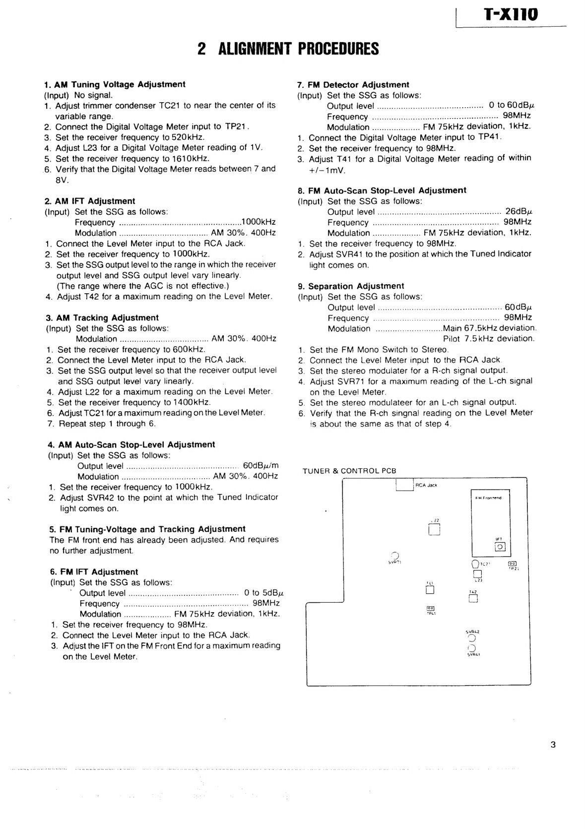
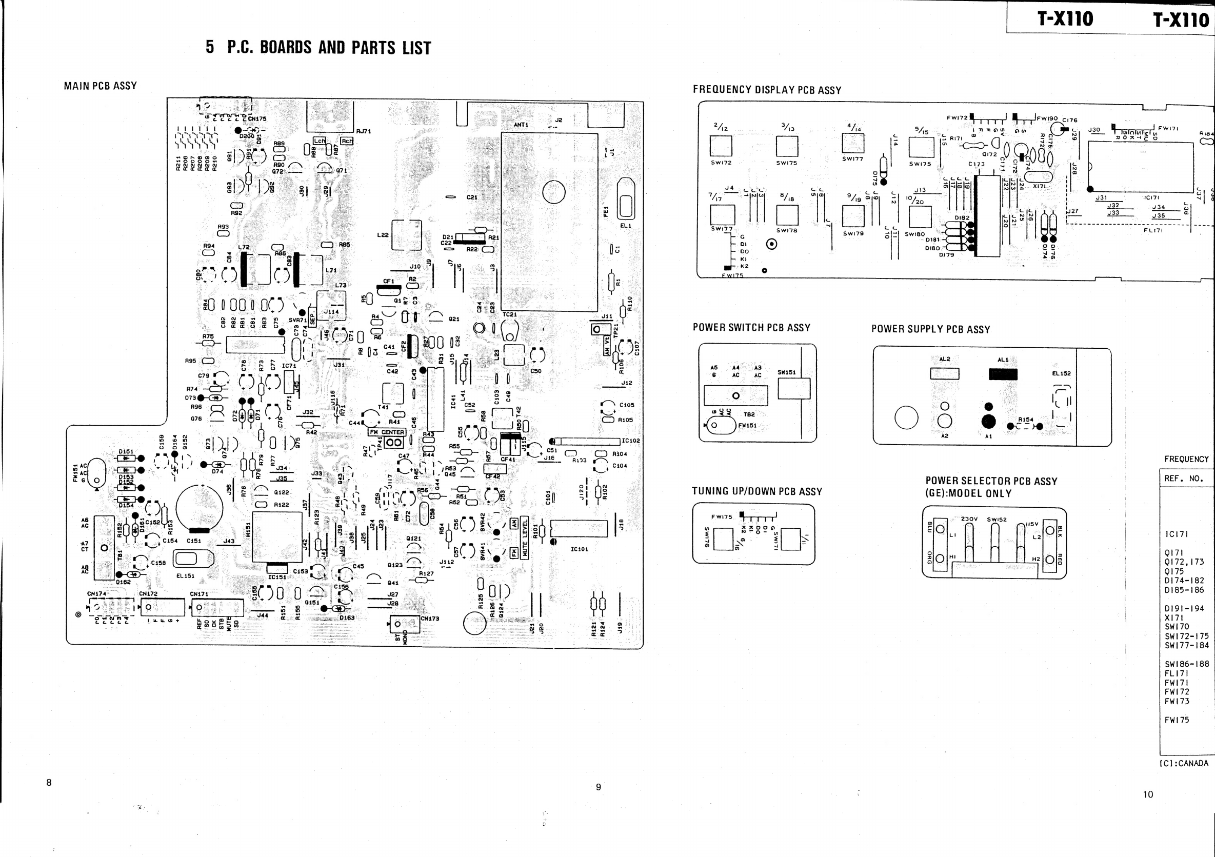
TUNER
&
CONTROL
PCB
FM
Frontend