Team CRC Carpet Knifea 3 User guide
BEVEL BATTERY SLOTS
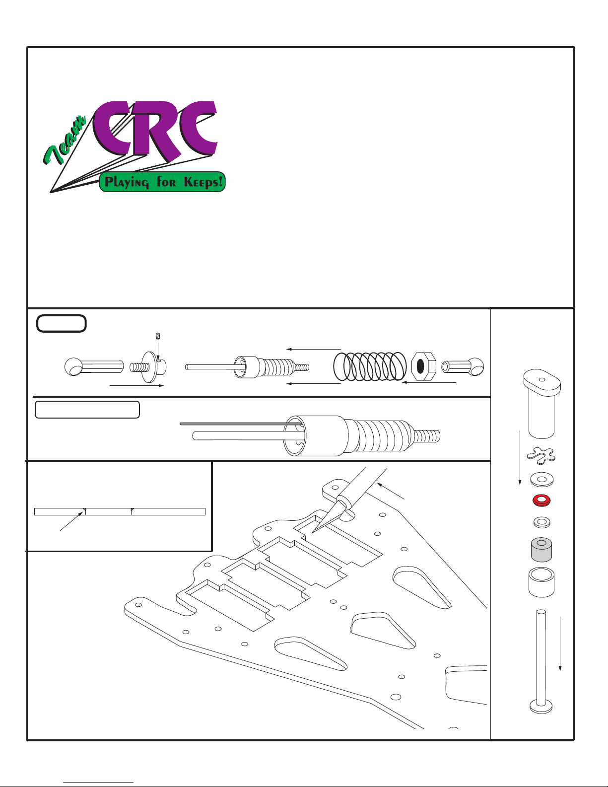
DISASSEMBLY
1. DO NOT file the battery slots! The
slots are pre-machined to allow the batteries to sit
flush with the bottom of the chassis.
**Optional** - You may wish to slightly chamfer the sharp edges. Do this by
lightly dragging a sharp X-acto blade across the sharp edge of the graphite.
Remove sharp edge- DO NOT FILE!
Shock 1) Build the shock per the instructions included in Bag "S". Use FSR or Asc 30 weight silicone
oil. After the shock is built, set it aside for mounting later. Center Shock
Assembly
Calandra Racing Concepts
Carpet Knifeä
Version 3
Assembly and Setup Manual
Congratulations! You now own the best 1/12th scale car on the market today, the Carpet KnifeäVersion 3. This completely new car
sets higher standards in pan car design, performance and convenience features. Calandra Racing is proud to have you as an owner
of the new Carpet Knifeä! Build this car carefully and precisely. It will bring years of enjoyment and performance.
1

Use the instructions included in Bag "F" to
help you assemble the front end. Bolt the
assembly to the chassis as shown below.
USE GREEN SCREWS FROM BAG X TO
FASTEN FRONT END TO CHASSIS!!
***** USE THE GREEN ALUMINUM
SCREWS FROM BAG "X/F" *****
Both Left + Right sides.
**Optional Kydex Bumper**
CRC #1357
Bag "F" and Bag "X"
Adjust front body height
Bolt the universal servo mounts in these 2 holes
Adjust the mounts to center the servo saver.
Use the screws from Bag "F" for the servo mnt.
Bag X includes CRC's
unique "Universal Servo
mount". This mount
accepts all "mini" type
servos. We have tested it
with JR, Futaba, Airtronics
and HiTech mini servos.
A .20" spring
is included in
the kit. Try
.18" for more
steering
response.
Use the shims to remove play in the
steering block. Shim the king pin so
that the shims stack up to a level
even with the e-clip groove.
2

Bag "R" and Bag "1"
Bag "6"
Long
Screw
Keep these 2 loose for now.
Tighten and align later when
installing side links.
Longer Screws
tighten
firmly
Install the 2 small 2-56 button
head screws - Do not over tighten.
Pivot ball must move freely.
Holes are
oversized to
allow for
adjustment.
This part
"floats" to
allow links
to be free.
From Bag "3"
From Bag "3"
Side View
Hex Pivot
Ball
Alum
cone
Bag 1 contains the graphite bottom plate,
aluminum cone, and hardware. Mount the
hex pivot balls (from Bag 2) securely by
tightening them with a 3/16" nut driver. Do
not use the screw head to tighten the hex balls.
hex nut 2 hex nuts
small ID
washers
Mounted Pivot Assembly (football shaped).
Shown here with the rear lower pod removed.
Don't forget to trim the plastic pivot ball cups
as shown above.
Installing the Rear Pod
Mount the Battery brace using these 2
holes. Stack the cones to form an "hour-
glass" shape. Then place the brace
above the cones and lock with a nut.
Bag 8
3
locknut
Small
washer
Large
Alum
washers
2 hex
nuts
Pivot Plate
TRIM Plastic!
For Motor + Battery
Clearance

A) Trim black spring
holder as shown.
B) Snap spring onto
trimmed plastic holder.
C) Thread set screw stud
into cross brace. Then
thread into spring holder
about 3/32 of an inch.
Bag "3"
Tweak
Assembly
Bag "5"
Rear top plate
A) Bolt Tweak Assembly to chassis through the
aluminum standoffs. Use the 4-40 button head
screws.
B) Fasten the rear top plate to the rear bulkhead
set with the 4-40 button head screws (3).
C) Later, we will attach the 2 damper tubes to the
ball studs.
D) Tighten or loosen the "tweak screws" so that
springs just touch the spring perch ball.
Use these 2 holes to mount the battery
brace. Stack the cones so that they form a
"hour-glass" shape. Run the long screw up through the
bottom of the chassis, through the 2 cones and brace. Then use a locknut.
****Be sure that the small "cut" in the brace faces to the front of the car!!!****
Thread the 2-56 balls into the graphite from the bottom.
Then, mount the larger 4-40 ball from the top and secure
with a locknut.
Use the 3 button head
screws to fasten the
Top Plate to the
rear bulkheads.
Bag 8
4

1) Find the Damper tubes in Bag #4. Clean the aluminum tubes with a cotton swab to ensure there is no aluminum filings in the tube.
2) Assemble by threading the 2-56 studs into the black plastic ball cups. Thread in fairly deep with only about 1/8" of the thread protruding. Now, thread
one ballcup into the aluminum tube and the other into the black delrin plunger. Using Losi Hydra fluid, cover the plunger with fluid, filing the slots
with fluid. Be sure the vent hole is clear. Insert the plunger in the tube and wipe the excess fluid. The tubes are now ready to install.
3) At this time, do not install the damper tubes. We will do that later. The tubes are shown here for illustration purposes only. They snap on the balls.
Bag "2", Bag "4" and Bag "7"
Battery Hook
4) Bag #7. Install the battery hook standoffs as shown below. The countersunk washer catches the
O-ring retainer that secures the battery.
5) For the next step, which is the 1-piece link installation, remove
the top tweak brace so that the pivot plate (football shaped
piece) is exposed from the top. Do this by removing the 2
button head screws that are right behind the body mounts.
6) Be sure the 2 aluminum locknuts on top of the
pivot plate are loose. Notice that the pivot plate
"floats" or moves slightly on the 2 screws. This
"floating" allows the links to "free up". This
ensures that the rear pod plate pivots
freely on the links and center
pivot ball. This is a crucial step
when setting up the Carpet Knife.
7) To begin the link installation, secure
the hex-pivot balls to the chassis with the
screws provided in Bag "2". Tighten the
pivots firmly using a 3/16" nut driver. Hold the
screws from underneath the chassis, but
TIGHTEN the balls from above with the nut
driver. If you try to tighten from underneath, you
will strip out the head of the screw. Use the larger
nut driver to tighten as this larger surface will not
strip as easy.
Use short
screws for
batt hook.
Bag "2" One-piece links
1) With the top Tweak brack removed, locate the football shaped
graphite part. Be sure the 2 exposed top locknuts are loosened slightly.
2) Snap the 2 links on the balls as shown. They should rock freely on
the pivot balls. Do NOT install the center shock yet, if you have
already, remove the center shock.
3) Place the car on a flat surface. A smooth table or desk should do.
Be sure that the rear bottom plate and chassis are in a straight
line, flat against the table. Keep the car flat on the table for
step 4.
4) Now, slowly tighten the 2 locknuts that secure the pivot
plate (football shaped part). Snug them down firmly.
5) Pick up the car and check the pivoting action of
rear lower plate. Rotate the rear plate from side-to-
side. It should move free without binding or "clicking".
If it does not, repeat steps 1-4. The handling of the
Carpet Knife hinges (pun intended!) on the free
movement of this rear plate. Be sure that the rear
links and rear plate are free and not binding.
6) Snap the center shock on the 2 balls as shown. With the
car suspended in the air, see that the rear pod is level or droops
slightly (viewed from the side). Extend (loosen) the black plastic ball
cups to lengthen the shock. Cut the ballcup or tighten it to shorten
the length of the shock. This will effect the droop of the rear plate.
Hex
pivot ball
From Bag "S"
5
Rotate
IMPORTANT! - If the links bind or drag, free them up by popping
them on and off a few times. This will loosen them so that they rock
freely when popped on. In severe cases, squeeze the plastic link with
pliers while they are popped onto the metal hex-balls. You can also
polish the balls slightly with a polishing compound.
Middle Hole!!!

1 42
1 42
SAME FOR THE OTHER SIDE
Bolt the left wheel with the long screws provided.
Bag "D"
Differential axle assembly
1) Use the above ride-height adjusters to set the rear height of the car. The
adjuster you use depends on the rear tire size.
2) Push the flanged bearings from Bag "B" into the ride height
adjusters. Press the plastic adjuster into the bulkhead as shown.
3) Assemble the diff as shown. Use FSR/CRC white diff
grease on the balls. Tighten the nut so that the gear will
not slip when both left + right wheels are held.
Optional-you can pin the right wheel to the diff
hub to ensure it does not slip
under high acceleration.
1) Install 2 small bearings from
Bag "B" in each front wheel.
2) Use an e-clip to fasten each wheel
to the axle.
Optional - Use CRC# 4114 Titanium
stub axles w/ locknuts to fasten each
wheel. These eliminate the e-clips.
6
Optional - You may want to use a 4-40 set screw in the
diff hub to prevent the wheel from spinning on the hub
under hard accelleration. The hub is tapped 4-40.
Popular Motorized Toy Car manuals by other brands


Serpent
Serpent S240 Instruction manual & reference guide

Arrma
Arrma 1/8 INFRACTION 4X4 3S BLX 4WD All-Road Street Bash Resto-Mod Truck... Get started

Reely ROAD
Reely ROAD XL Maximus II operating instructions

Kidi Race
Kidi Race School Bus owner's manual

Xray
Xray T1R Raycer Set-Up Book

Traxxas
Traxxas BANDIT VXL manual

LRS
LRS Narrow Planet NPL-008 Assembly instructions

HPI Racing
HPI Racing Atsushi Hara edition Pro4 instruction manual

Kogan
Kogan KAMERCVTBKA user guide

Agora
Agora SHELBY COBRA 427 SEMI-COMPETITION 1965 Build instructions

Fisher-Price
Fisher-Price BOUNCE N GO Coupe G4815 instructions

Silverline
Silverline SLK 114 Assembly instructions