Team Digital SC82 User manual

"
TEAM DIGITAL
1
SC82
Servo Controller
Improving the world of DCC
>DCC compatible accessory decoder
> Control 8 servos motors
> Output status LEDs
> 8 inputs for turnout control
> 16 inputs for semaphore signaling
> 8 configurable routes
> “Smart” Programming
>DCC gateway to serial bus
> LocoNet® compatible serial bus
Description
The SC82 is a DCC compatible accessory decoder.
It can control up to 8 servo motors that can be used
for switches (turnouts) or semaphores. It can drive
LEDs for turnout state. The inputs can be used for
push buttons to control switches or block detectors to
control semaphores. It has route capability for
multiple turnout control.
The SC82 can be used as a stand-a-lone controller or
communicate with other devices that have a
compatible serial bus.
Using the serial bus, one SC82 could control another.
Push buttons connected to the inputs of one SC82
can control servo connected to another SC82. A route
defined in SC82 could include servos controlled by
another SC82. The serial bus can help in reducing
and simplify the wiring.
The SC82 works out of the box with no
programming. If you you need to change servo
position or addresses its as easy as issuing switch
commands or controlling loco speed. If custom
operation is required, CVs can by programming by
the DCC system.
TEAM DIGITAL, LLC
3111 Timber Valley Dr
Kokomo IN 46902
www.teamdigital1.com
09.01.15
LocoNet is a registered
trademark of Digitrax Inc
PRELIMINARY
Version C proto hardware shown.
Production hardware has all servo
connectors in one line.
1
1
1
1
Inputs
1 to 8
Inputs
9 to 16
Outputs
9 to 16
Outputs
1 to 8
SC82
LED1
LED2
LED3
Power
Track Power
or DC
9.5 -16 V Serial Bus
6 pin RJ12 Smart Button
Inputs for:
Push button switch control
Semaphore signaling
Outputs for:
LED indicators
Serial bus used to communicate:
Switch state/control
SG 5V GDSG 5V GD
1
4
5
8Outputs for:
Servos
Inputs only for:
Semaphore signaling

1 Operation 3
1.1 LED Indicators 3
2 Getting Started 3
2.1 Control via LocoNet - Digitrax Users 3
2.2 Servo Mounting 3
2.3 Servo Move Direction 3
2.4 Switch Position Indication 3
3 “Smart” Programming 4
4 Configuration Variables (CVs) 6
4.01 Changing servo position 6
4.02 Reset the SC82 to factory defaults 7
4.1 Servo Output Address 7
4.2 Servo Position and Range 7
4.3 Servo Move Speed 7
4.4 Decoder Configuration 7
4.5 Status Report 8
4.6 Input Control 8
4.7 Route Execute Address 9
4.8 Route Cell Address 9
4.9 Route Address Send Delay 10
4.10 Operations Mode Loco Address 10
4.11 Input Lockout Address 10
4.12 Power On Output State 10
5 Connections 11
5.1 Power 11
5.2 Input Interface 11
5.3 LED Output Drive 11
5.4 10 PIN Input and Output 11
5.5 3 PIN Servo 11
5.6 Serial Bus 11
6 Applications 12
6.1 Wiring Examples 12
6.2 Routes 13
6.3 Simple Semaphore Signaling 13
7 Summary of Configuration Variables 15
2

1 Operation
The SC82 is capable of driving eight servo motors. Each output (servo) can individually be assigned any switch (turnout)
address. It has eight inputs for local control of the outputs and eight programmable routes.
There are two modes of operation. The modes are based on how the servo is used. All servo outputs function in either mode 1
or 2 i.e. modes can not be mixed between servo outputs.
The first mode is moving all servos to two positions (default).
Mode 1 - The servo outputs can be used for switch (turnout) control. There is a separate switch address for each output so
they can be controlled individually. There are a total of eight switch addresses used.
The second mode is for moving all servos to three positions.
Mode 2 - The servo outputs can be used for semaphore control. There are 24 switch addresses used. In this mode three
addresses are used to control each servo, address A(throw) will command the servo to one end, address A+1(throw) will
command it to the center and address A+2(throw) will command it to the other end.
The SC82 supports routes. A route allows for the control of multiple switches (turnouts) with just one switch command. Each
route is made up of eight cells (switch addresses) and one top level address (or route execution switch address). Each top
address is completely independent of a servo address. Complex routes with more than eight servo addresses can be created by
assigning the same address to more than one top level address. Routes are executed by issuing a switch command.
Since the SC82 is an accessory decoder, it can be controlled via DCC commands. It can also be controlled via the serial bus
(LocoNet® compatible). For non-Digitrax systems a DCC gateway feature allows DCC switch commands to be passed
directly to the serial bus. This allows DCC switch commands to control devices connected to this serial bus.
1.1 LED Indicators
LED 1 flashes indicates “Smart” programming. LED 2 flash indicates accepted program value or a valid received address.
LED 3 slow flash indicates heartbeat and fast flash indicates serial bus short.
2 Getting Started
The SC82 comes from the factory ready to use with addresses of 1 to 8. Once you plug in the servos cables, centered the
servos (section 2.2) and mounted them you are ready to use the SC82. If you want to change some of the addresses or adjust
servo movement see the “Smart” Programming section. For very custom programming see section 4, Configuration Variables
for various options. Before doing any programming, it is strongly recommended that you verify basic operation.
2.1 Control via LocoNet - Digitrax Users
The SC82 comes from the factory ready to use by control from DCC commands when it is connected to track power. To
control the SC82 via LocoNet®, it must be enabled. LocoNet® can be enabled using section 3, “Smart” programming Part 3 or
the programming track. If the programming track is used, connect the SC82 track power terminals to the programming track
and program CV9 with a value of 48. The SC82 can now be powered from a 12 volt supply and controlled via LocoNet®.
2.2 Servo Mounting
Before mounting and/or linking the servo arm (horn) to the turnout or semaphore, the servo should be centered and then the
arm attached so that when linked the turnout or semaphore will be in the approximate center of their travel.
To center the servo, press the Smart button then turn on power and continue to press the button until LED2 (green) begins to
flicker. Several seconds after releasing the button, all the servo will move to the center position.
NOTE: for mounting orientation it may be useful to know that a turnout throw command causes the servo to rotates CCW
when viewing the servo shaft (factory default operation).
2.3 Servo Move Direction
It may be that after you have installed the servos issuing a close or throw command causes the switch to move to the opposite
intended position. That is, close causes the switch to move to the thrown position. The direction can be reversed without
programming if a push button is used for switch control. To reverse the servo direction press and hold the “Smart” program
button until after power is turned on. If LED2 (green) begins to flicker you have pressed the “Smart” button too long. After
power has been on for at least 5 seconds, press and hold the respective push button for the servo to be reversed for at least 4
seconds. Direction can also be changed in “Smart” programming Part 2.
2.4 Switch Position Indication
If LEDs are used to indicate the status (position) of the switch on a panel or facia, they will flash during the time the
respective servo is moving. It may be that after they are installed that the lighted color does not match the switch position.
That is, green may be lit instead of red. The lighted color can be reversed without programming if a push button is used for
switch control. To reverse the lighted color during normal operation, press and hold the push button for at least 4 seconds.
3

Once you notice the change release the button. The LEDs may be
flashing during this time. Also the SC82 must NOT be in the same
mode as when change the servo direction mode.
3 “Smart” Programming
“Smart” programming is a term used to describe an easy way to
program Configuration Variables (CVs). A controller (any device used
for locomotive or switch/accessory control) is used to issue switch
(turnout) or accessory commands. Additionally, loco speed commands may be used.
“Smart” programming only works when the SC82 is connected to track power.
There are three parts to “Smart” programming. You can:
1. change the addresses of the inputs and servo outputs, either for switch control (two servo positions) or semaphore control
(three servo positions).
2. change the amount of servo movement and positions.
3. set the SC82 configuration and status report options.
To program in “Smart” mode, connect the SC82 power terminals to track power. The serial bus (LocoNet® in Digitrax
systems) should NOT be connected to the SC82 during “Smart” programming.
To start turn on track power. Wait 6 or 7 seconds.
You can start from any part. Also at any time you can exit “Smart” mode by pressing the button for approximately one second
until LED1 stops flashing.
Part 1: To change addresses and mode, press the “Smart” program button and hold it down for approximately one second
until LED1 (red) starts to flash. Then release it. The SC82 is now ready to have the addresses changed. You can set eight
sequential addresses in one (first) step or continue and set each of the individual servo addresses (non-sequential). Input
addresses are also changed. SC82 Configuration is unchanged.
Eight sequential addresses:
Using the controller select the switch address or accessory number you want for the start of eight sequential addresses and
issue a close (normal) command for two positions (mode 1). Issue a throw (reverse) command for three positions (mode 2).
Now press the “Smart” button until LED1 stops flashing, the SC82 will restart and be ready to use with the new addresses.
Non-sequential addresses:
Using the controller select the
switch address or accessory number
you want for the first servo output
address and issue a close (normal)
command for 2 positions (mode 1).
Issue a throw (reverse) command
for 3 positions (mode 2). LED1 will
be flashing twice with a pause and
then repeats indicating that the servo
2 output address is ready to be
programmed. Select the switch
address you want for the second
servo output address and issue the
same close/throw command as in
step one.
Servo 2 position and 3 position modes can NOT be mixed.
Smart Programming Part 1 - Change addresses and or mode (sequential addresses)
Part 1: To start - Press the “Smart” button until LED1 starts to flash
LED1
#Flashes
Description
t
c
Example
1
Select beginning address for 8 sequential addresses
3 position
(mode 2)
2 position
(mode 1)
9
c
To stop - press the “Smart” button until LED1 stops flashing, the SC82 will then restart and be ready to operate
4
For example, to
set servo
addresses 9-16 in
mode 1, select
switch address 9
and issue a c
(close) command
Switch (Turnout) Terminology
This manual
throw or t
close or c
Digitrax
throw or t
close or c
NCE
reverse or OFF or 2
normal or ON or 1
Lenz
-
+
MRC
OFF
ON
Smart Programming Part 1 - Change addresses and or mode (non-sequential addresses)
Part 1: To start - Press the “Smart” button until LED1 starts to flash
LED1
#Flashes
Description
t
c
1
Select servo 1 output address
3 position
2 position
Continue to step 2 for non-sequential addresses
2
Select servo 2 output address
3 position
2 position
3
Select servo 3 output address
3 position
2 position
4
Select servo 4 output address
3 position
2 position
5
Select servo 5 output address
3 position
2 position
6
Select servo 6 output address
3 position
2 position
7
Select servo 7 output address
3 position
2 position
8
Select servo 8 output address
3 position
2 position
After the last step the SC82 will restart and be ready to operate

As you progress through the “Smart” programming steps, LED1 flashes the number of times indicating which servo output is
ready to be programmed. After the 8th step the SC82 will restart and be ready to use with the new addresses.
Note: servo 3 position (mode 2) used for semaphore requires 3 addresses, one for each position. Enter only the first address
and be sure to skip at least 3 addresses when programming. You can exit “Smart” programming after any step by pressing the
“Smart” button until LED1 stops flashing.
Part 2: To change servo position press the “Smart” program button and hold it down. After about a second LED1 (red) starts
to flash. Continue to hold it down until LED2 (green) turns on. Then release it. LED1 will be flashing and LED2 will be on.
The SC82 is now ready to have the servo movement changed. You need to be able to see the servo arm, switch or semaphore
to make adjustments.
Using the controller select a loco address (not a switch address) that corresponds to the servo output (1-8) that is to be
changed. For example select loco 2 for output 2. Adjust the speed of the loco to move the servo. Set the loco to forward to
move the servo in one direction, set the loco to reverse to move it in the other direction.
To program the switch position for close, use the manner just described and move the servo to the position you want it to be
in when closed. Now issue a switch close command with address 1.
To program the turnout position for throw, use the manner just described and move the servo to the position you want it to be
in when thrown. Now issue a switch throw command with address 1.
The switch address (1-8) is used for programming the servo position of the respective output. If a switch address higher then
8 is used, the SC82 will restart and be ready to use with the new positions. You can also exit “Smart” programming by
pressing the “Smart” button until LED1 stops flashing.
Note: The controller must be set for 128 speed steps and there should not be any other locos addresses selected in the 1-8
range.
Part 3: To change the SC82 Decoder Configuration and/or the Status Report options press the “Smart” program button and
hold it down. After about a second LED1 (red) starts to flash. Continue to hold it down until LED2 (green) turns on and then
off. Then release it. The SC82 is now ready to have the options changed. LED1 (red) will be flashing.
The CV value is the switch address you select. For example, to enable the serial bus and disable DCC control for a Digitrax
system select a switch address of 48 and issue a throw command.
Smart Programming Part 2 - Set (Program) Servo Position
Part 2: To start here - Press the “Smart” button until LED2 lights - Output addresses are not changed
Loco
address
Description
t
c
1
Use loco address 1 speed and direction to position servo 1
Issue switch address 1 to set (program) the position
set throw
position
set close
position
2
Use loco address 2 speed and direction to position servo 2
Issue switch address 1 to set (program) the position
set throw
position
set close
position
3
Use loco address 3 speed and direction to position servo 3
Issue switch address 1 to set (program) the position
set throw
position
set close
position
4
Use loco address 4 speed and direction to position servo 4
Issue switch address 1 to set (program) the position
set throw
position
set close
position
5
Use loco address 5 speed and direction to position servo 5
Issue switch address 1 to set (program) the position
set throw
position
set close
position
6
Use loco address 6 speed and direction to position servo 6
Issue switch address 1 to set (program) the position
set throw
position
set close
position
7
Use loco address 7 speed and direction to position servo 7
Issue switch address 1 to set (program) the position
set throw
position
set close
position
8
Use loco address 8 speed and direction to position servo 8
Issue switch address 1 to set (program) the position
set throw
position
set close
position
5

Once the switch command has been issued, LED1 will be flashing twice with a pause and then repeats indicating that the
Status Report options are ready to be programmed.
4 Configuration Variables (CVs)
The SC82 supports Paged Mode Programming in Service Mode and Operations (Ops) Mode programming. To program
in paged mode, connect the Track Power terminals to the programming track. See diagram on the front page. When power is
applied, LED 1 will come on and LED 2 will flash when programming is successful. Some systems only apply power during
actual programming, so LED1 will only be on during that time. The SC82 does not have built in feedback like a mobile
decoder. Therefore, some systems may show a “no decoder on track” error or “can not read CV”. However it still is
programmed. To enter normal operation, disconnect from the program track and connect as defined is section 5.
To program in ops mode (On the Main Programming) connect the power terminals to track power. Hold down the Smart
button just before power is turned on. When the green LED turns on release the button then wait until the red LED turns off.
The SC82 is now in ops mode until power is turned off. The default ops address is one (1). This is a loco address, so be
careful when using this feature. The SC82 can be programmed so it is always in ops mode by setting option 3 in CV9.
When using ops mode to change CV values, the SC82 does not recognize some new values until power is turned off
and then back on. Programming CV7 with a value of 1 will restart the SC82 so power need not be cycled when
programming in ops mode. This is the same as turning power off and then back on. For programming with DecoderPro and
other programming tips see Team Digital’s web site.
4.01 Changing servo position
Once the SC82 is in ops mode the servos can be set to various positions. This is an alternative to using Smart programming.
To move the servo to the center, program CV7 with a value of 2.
To move the servos to one end program CV7 to a value of 4.
To move the servos to the other end program CV7 to a value of 5.
To move the servo to the center with power save off, program CV7 with a value of 6.!
Smart Programming Part 3 - Change Configuration and Status Report
Part 3: To start here - Press the “Smart” button until LED2 lights and hold until it turns off
LED1
#Flashes
Description
t
c
Example
1
Decoder configuration
set
clear
48
t
2
Status report (useful only with serial bus and mode 1)
set
clear
48
c
After the last step the SC82 will restart and be ready to operate
Decoder Configuration (Section 4.4)
Value
Select
No options
0
Option 2 - enable fixed output state at power on
2
Option 3 - enable ops mode programming
4
Option 4 - enable DCC to serial bus gateway
8
Option 5 - enable serial bus communication
16
Option 6 - disable control from DCC
32
Option 7 - disable power save
64
Option 8 - enable common cathode
128
Configuration values total
Status Report (Section 4.5)
Value
Select
No options
0
Option 1 - Send input state at power on enabled
1
Option 2 - Send output state at power on enabled
2
Option 3 - Interrogate input state enabled
4
Option 4 - Interrogate output state enabled
8
Option 5 - Use 1 LED output instead of 2 to indicate servo position
16
Status Report values total
6
Example: clear (zero) the status
report CV. When a c (close)
command is issued, the switch
address is unimportant.
Example: for Digitrax systems,
select switch address 48 and
issue a t (throw) command. 48
is 16 (enable serial bus) plus 32
(disable DCC control).
State Report Options 1- 4 are
only useful if the serial bus is
enabled.
Options 5 is used with the
optional 3 wire button/LED
interface board.

4.02 Reset the SC82 to factory defaults
To “reset” the SC82 to factory defaults, turn power on and wait until LED 1 turns off. Then press the “Smart” button and
continue to hold the button down (at least 16 seconds) until both LED 1 & 2 are alternately flashing. Alternately,
programming CV7 with 170 will “reset” all CV’s to the factory default value. In page mode this may not work with some
systems as they do not keep power applied to the programming track long enough for all the CVs to be programmed.
4.1 Servo Output Address
CV56-71 - These CVs determine the address of the
servo outputs. Each output has two CVs, an address
and an address adder, that makes up the address.
f an address greater than 255 is needed then use the
address adder. The address adder value represents a
number that is added to the address value to give
the ‘actual’ address. The following table shows the
CV value to use for the adder.
4.2 Servo Position and Range
CV72-87 - There are two positions the servo can move too in Mode 1. These positions are determined by two CV values for
each servo. The servo will move to position 1 when a close command is issued and position 2 when a throw command is
issued. The difference between these two positions determines the servo movement or range.
In Mode 2 the the center position is half way between position 1 and 2.
4.3 Servo Move Speed
CV88-95 - Move Speed Direction 1, a maximum value of 127.
CV96-103 - Move Speed Direction 2, a maximum value of 127.
These CVs determine the servo’s speed when it moves. The larger the number the slower the servo moves. A value of zero
will cause the servo to move at it’s maximum speed.
Note: Reasons why you may see the servo move strangely or at maximum speed at power on even if the servo move speed
has been set to a very slow value.
1. If the servo position is changed during power off.
2. Some servos twitch, jump or move erratically when power is first applied to them.
3. Some inexpensive servos have poor performance.
4.4 Decoder Configuration
CV9 - This CV determines the configuration
which consists of several options.
* Note: Setting the SC82 mode by programming
this CV does not change any of the servo or
input addresses. To change modes and or
addresses use “Smart” programming.
Option 2 - Default output state. At power on
each output will be set to the state as determined
by CV12 and CV13. You must program CV12
and CV13 to the desired state at power on. See
section 4.x.
Option 3 - Ops Mode Programming. Allows Operations mode (On the Main) programming using a Loco address to be
enabled all the time. See section 4.10.
Option 4 - DCC to bus gateway. Allows DCC switch command packets to be put the serial bus. Any device connected to the
bus will have access to these DCC commands. Requires option 5.
Option 5 - Serial Bus communication. Allows the SC82 to communication with devices connected to the serial bus.
Option 6 - DCC control. Allows the SC82 to receive instructions from DCC (track). Note: Selecting this option DISABLES
this feature.
Address Adder
CV Value
0
1
2
3
4
5
6
7
8
9
ADD
0
256
512
768
1024
1280
1536
1792
2048
2304
7
Servo Output
Address CV
Value
Select
Address
1 - 255
Program this value into the appropriate address CV
Address Adder
Value
Select
Address adder (see the address adder table for the value)
0 - 9
Program this value into the appropriate type CV
Decoder Configuration (Section 4.4)
Value
Select
No options
0
Option 2 - enable fixed output state at power on
2
Option 3 - enable ops mode programming
4
Option 4 - enable DCC to serial bus gateway
8
Option 5 - enable serial bus communication
16
Option 6 - disable control from DCC
32
Option 7 - disable power save
64
Option 8 - enable common cathode
128
Configuration values total

Option 7 - Power save.
Reduces power when servo
are not moving. Note:
Selecting this option
DISABLES this feature.
Option 8 - Common cathode
LEDs. Allows common
cathode connection of LEDs
to the outputs.
To calculate the value of
CV9, add up the selected
values. Example: Option 1
and option 3 - CV9 = 1 + 4 =
5
This table will help you determine how to configure the SC82. If there are more than one SC82 or other Gateway capable
devices, only one should have the gateway enabled. In a Digitrax system DO NOT connect the SC82 to the throttle Loconet if
the gateway, DCC control and serial bus are enabled. This could cause an endless sending of switch commands from the track
to Loconet and back to the track.
4.5 Status Report
CV10 - This CV determines which input and output states the SC82 reports (Options 1- 4) when used fore turnout control and
useful only when the serial bus is enabled. This will not work correctly if the servos are configured for mode 2 (3 positions).
This also determines how the LED driver outputs are configured. These options can be enabled in part 3 of Smart
Programming.
Option 1 - Input state messages are sent on the
serial bus at power on. This options is typically
used for inputs that are used for block detection
or turnout feedback. This does NOT apply to
inputs that are used for switch (turnout) control.
Option 2 - Output servo position (state)
messages are sent on the serial bus at power on.
These are switch type messages. Do NOT
enable option 4 at the same time.
Option 3 - Input state messages are sent on the serial bus when a Digitrax interrogation command is received.
Option 4 - Output servo position (state) messages are sent on the serial bus when a Digitrax interrogation command is
received. These are feedback type messages. Do NOT enable option 2 at the same time.
Option 5 - One LED output is used to indicate servo position. This is required if you want to connect two LEDs and a push
button by a 3 wire servo cable to the SC82. A 3 wire interface board is required. See section 6.1.
4.6 Input Control
CV16-39 These CVs determine what action the inputs 1-8 will have when activated. (Inputs 9-16 are used for semaphore
signaling and can not be independently programmed.) There are three CVs for each input. An address, type and transition CV.
See section 7 for CV numbers. If an address greater than 255 is needed then use the address adder. The address adder value
represents a number that is added to the address value to give the ‘actual’ address.
They can each be programmed to operate independently and are not linked or connected to the outputs in any way except by
a common address and type.
In order for an input to cause an action, including executing a route, a transition must be selected. The input is normally at 5
volts. An input transition occurs when the voltage on an input goes from high to low (falling edge) or from low to high (rising
edge). For example, if a push button is connected to an input and ground, when it is pressed the input is grounded. This
causes a high to low transition. When the button is released this causes a low to high transition.
To set addresses for both inputs and outputs see “Smart” Programming for easier programming.
8
System
DCC
Control
Option 6
Gate-
Way
Option 4
Serial
Bus
Option 5
CV
Value
Notes
All DCC
Compatible
Systems
Enabled
0
The SC82 is controlled via the track (DCC
commands).
The bus is not used by the SC82.
Digitrax System
Disabled
Enabled
48
The SC82 is controlled via Loconet.
Digitrax System
Enabled
Enabled
Enabled
24
Provides a separate Loconet bus for
Loconet accessory devices.
Allows devices to receive turnout commands
from the track (DCC commands).
Reduces throttle bus traffic.
NCE System
and others
Enabled
Enabled
Enabled
24
Provides separate bus for bus enabled
accessory devices.
Allows devices to receive turnout commands
from the track (DCC commands)
Status Report
Value
Select
No options
0
Option 1 - Send input state at power on enabled
1
Option 2 - Send output state at power on enabled
2
Option 3 - Interrogate input state enabled
4
Option 4 - Interrogate output state enabled
8
Option 5 - Use 1 LED output instead of 2 to indicate servo position
16
Status Report values total

4.7 Route Execute Address
CV112-127 - These CVs determine the top or execute address of a route. Each top address is completely independent of an
input or output address. A route is executed when a turnout (switch) command from any source including those from the
SC82, throttles or computers matches the top address and switch state for that route. To increase a route to greater than than
eight turnouts, give more than one top address the same address. When a route is executed, turnout commands are sent for
each cell containing an address. Optionally, a route can be executed by a block sensor message. In this way several turnouts
can automatically be alined when a block becomes occupied.
4.8 Route Cell Address
CV128-255 - These CVs determine the address in a route cell. When a route is executed all cell addresses are sent one at a
time. For all addresses in a route to be sent there must be no empty cells between cells with addresses.
Input Control
Address CV
Value
Select
Address
1 - 255
Program this value into the appropriate address CV
Type CV
Value
Select
Invert the normal state
128
Select
Normal state
0
one
Toggle state (only if switch type)
64
Message type, sensor
32
Select
Message type, feedback (actual switch position)
16
Message type, switch (commanded switch position)
0
one
Address adder (see the address adder table for the value)
0 - 9
Program this value into the appropriate type CV
Transition CV
Value
Select
Execute route number x 16 (example to execute route 2, 2 x 16 = 32)
*
0 - 1218
Send message on change transition
3
Select
Send message on hi to low transition
2
Send message on low to hi transition
1
One
Disable message
0
Program this value into the appropriate transition CV
Route Top (Execute) Address
Address CV
Value
Select
Address
1 - 255
Program this value into the appropriate address CV
Type CV
Value
Select
Close
64
Select
Throw
0
one
Execution type, sensor
32
Select
Execution type, switch (turnout command)
0
one
Address adder (see the address adder table for the value)
0 - 9
Program this value into the appropriate type CV
Route Cell Address
Address CV
Value
Select
Address
1 - 255
Program this value into the appropriate address CV
Type CV
Value
Select
Close
64
Select
Throw
0
one
Address adder (see the address adder table for the value)
0 - 9
Program this value into the appropriate type CV
9

4.9 Route Address Send Delay
CV11- Send address time delay, value 0 to 255.
This CV determines the time delay the SC82 waits before sending the next address in a route. Some switch machine drivers
require a time delay between switch activation.
4.10 Operations Mode Loco Address
CV1 - Ops mode address, a value of 1 to 127. Default is one (1). (If using Loconet and JMRI higher values are allowed.)
This CV sets the operations mode program address. This address is used ONLY for programming and has NOTHING to do
with normal operation. This allows programming the SC82 just like you would a loco in ops mode. This is a loco 2 digit
address and therefore must be unique among locomotive addresses. Option 3 must be enabled to use this address for
programming on the main. The programming track is not required once this address and option 3 have been set.
TIP: If the “Smart” program button is pressed when power is turned on, option 3 (ops mode) is enabled until power is
removed. Useful if you do not want to have ops mode enabled all the time.
4.11 Input Lockout Address
CV14 - Address, value 0 to 255: CV15 - Address adder, value 0 to 9
These CVs set the input lockout address. When a switch (turnout) throw command is issued that matches this address the
SC82 inputs are disabled. When a close command is issued with this address the inputs are enabled. This feature is useful for
dispatcher control when the SC82 inputs are used for local turnout control.
4.12 Power On Output State
CV12 - Power on state for output groups 1 to 4
CV13 - Power on state for output groups 5 to 8
These CVs determine the state of each output at power on. Decoder configuration option 2 has to be enabled for these CVs to
function. Normally the SC82 sets the servo position to the same state as they were in when power was turned off.
To program these CVs to set the outputs to a fixed state at power on do the following.
1. Enter normal operating mode and command each of the outputs to the desired state.
2. Enter Smart programming mode Part 3 and program CV9 (enable option 2).
3. Exit programming mode.
Now at each power on, the outputs will go to the same state as set in step 1
Delay between sending route addresses
CV11 Value
0
1
2
4
8
12
16
20
Delay (sec)
0.23
0.45
0.68
1
2
3
4
5
10

5 Connections
5.1 Power
The SC82 is powered by using the two terminal connector labeled Power. See diagram on front page. Power can be from the
track (accessory decoder operation) or a filtered DC voltage (9.5 to 12 VDC) power supply. For a DC supply do not use old
analog 'Power Packs'. The SC82 power connector is non polarized and either terminal can be connected to plus or minus of
the DC power supply. The power supply should be isolated from the system ground. That is, not connected to ground
(booster ground, house wiring ground, etc). When multiple SC82s are used they can be all connected to one power
supply. The plus and minus of the power supply must be connected to the same power input terminal on each SC82.
Power supply current requirements: 20mA for just a SC82, 20mA for each Tortoise™ using a MotoD. Good practice - select a
supply with at least 10% more current capability than required.
5.2 Input Interface
Each input has a 4.7K ‘pullup’ resistor connected to 5 volts, so the input is normally at 5 volts with respect to pin 5 (minus)
when no device is connected. This is a high or true state. When the input is connected to pin 5 (minus) by a push button
switch or block sensor, the input is “grounded” and the state is low or false.
5.3 LED Output Drive
The output connectors supplies 5 volts to drive LEDs. If LEDs are used current limiting resistors are required and should not
be less the 470 ohms. This is a general guide line for a typical LED. The current limit for any single output is 20 mA and the
total of any connector group of eight outputs (1-8 or 9-16) is 50 mA.
5.4 10 PIN Input and Output
Input and output connectors have the same pin definitions. Connections can be made using our terminal strip adapter (TSA)
or our Connector Cable Kit. You can build your own by using flat ribbon cable Insulation Displacement (IDC) and
connectors from Jameco. The mating connector is #138376. 10 ft of multicolor flat ribbon cable is #639672.
Warning: Do not connect the power supply ground (minus) to the ground (minus) pin 5 of the 10 pin IDC connector. Do not
connect any outputs
together or to other
SC82 outputs.
5.5 3 PIN Servo
The servo output
connectors have pin
definitions to match the
3 pin connector on
most servos. there are 3
pins per servo signal
(SG), 5 volts (5V) and
ground (GD).
5.6 Serial Bus
The SC82 has two
RJ12 connectors for
ease in making
connections as shown
below. In a Digitrax
system the data pins
are LocoNet and the RS
pins are Rail Sync. In a Digitrax system Rail Sync is a replica of the track
power signal but has limited power. One of its uses is to provide power to
throttles connected to LocoNet. In the SC82 the RS is not used
In a systems when more than 10 SC82s are used the bus terminating
resistor should be cut on any additional devices.
11
1
1
1
1
Inputs
1 to 8
Inputs
9 to 16
Outputs
9 to 16
Outputs
1 to 8
SC82
LED1
LED2
LED3
Power
Serial Bus
6 pin RJ12
SG 5V GDSG 5V GD
1
4
5
8
Input 2, Pin 2
Input 4, Pin 4
5 Volts, Pin 6
Input 6, Pin 8
Input 8, Pin 10
Pin 1, Input 1
Pin 3, Input 3
Pin5, Ground
Pin 7, Input 5
Pin 9, Input 7
Input 10, Pin 2
Input 12, Pin 4
5 Volts, Pin 6
Input 14, Pin 8
Input 16, Pin 10
Pin 1, Input 9
Pin 3, Input 11
Pin5, Ground
Pin 7, Input 13
Pin 9, Input 15
Output 10, Pin 2
Output 12, Pin 4
5 Volts, Pin 6
Output 14, Pin 8
Output 16, Pin 10
Pin 1, Output 9
Pin 3, Output 11
Pin5, Ground
Pin 7, Output 13
Pin 9, Output 15
Output 2, Pin 2
Output 4, Pin 4
5 Volts, Pin 6
Output 6, Pin 8
Output 8, Pin 10
Pin 1, Output 1
Pin 3, Output 3
Pin5, Ground
Pin 7, Output 5
Pin 9, Output 7
SG 5V GD
Servo Connectors
8
7
6
5
4
3
2
1
SG 5V GD
Data
RS
Ground
RS
Data
Ground
RJ12 Connector
Cables are wired pin 1to pin 1
Serial Bus
To other serial
bus devices
Termination
resistor
Cut
X
Serial Bus

6 Applications
6.1 Wiring Examples
These diagrams show wiring for push buttons and LEDs that can be used with the SC82 for switch control.
To use the 3 wire interface board, option 5 must be enabled in the Status Report CV. See section 4.5.
12
1
1
1
1
Inputs
1 to 8
Inputs
9 to 16
Outputs
9 to 16
Outputs
1 to 8
SC82
LED1
LED2
LED3
Power
Serial Bus
6 pin RJ12
SG 5V GDSG 5V GD
1
4
5
8
1
2
3
4
Product
Output#
7
8
TSA
Pin#
1
2
3
4
5
6
7
8
1 2 3 4 5 6 7 8 9 10
Pin#
TSA
GND - 5
5 volts - 6
Example of common
anode LED
indicators
TSA has built-in
resistors for LEDs
Ribbon cable
with connector
1
2
3
4
7
8
9
Product
Pin#
10
6 - 5 Volts
Input#
1
2
3
4
5
6
7
8
5 - GND
9
10
1
2
3
4
7
8
9
10
11
12
13
14
15
16
1 2 3 4 5 6 7 8 9 10
Pin#
TSA
GND - 5
5 volts - 6
9
10
Semaphore
signaling only
1
1
1
1
Inputs
1 to 8
Inputs
9 to 16
Outputs
9 to 16
Outputs
1 to 8
SC82
LED1
LED2
LED3
Power
Serial Bus
6 pin RJ12
SG 5V GDSG 5V GD
1
4
5
8
3 Wire interface board
Plugs on to SC82
input/output connectors 1-8
It will plug in either way but
only the way shown is correct
GD 5V SG
7
1
8
2
GD 5V SG
Ground - GD
5 Volt - 5V
Signal - SG
Both resistors 470 ohms
You can build your own 3 wire
control/display or purchase a
compatible device like the Touch
Toggle from Berrett Hill

6.2 Routes
The SC82 is well suited to handle routes
in a yard. The following shows an
example of five routes using four
switches. The route CV values were
determined using the information in
sections 4.7 and 4.8. One very nice tool
that makes custom programming much
easier is JMRI DecoderPro.
A route can be executed with an actual turnout (switch)
address or a pseudo address of a switch (not a physical
switch). Program the top address of the route with the
address you want to execute the route. Inputs can be
programmed to execute a
route from a push button.
6.3 Simple Semaphore Signaling
Simple ABS semaphore signaling of up to 8 semaphores can be implemented with just block and optionally turnout state
devices connected to the SC82 inputs. No programming is required except a couple of Smart programming steps. Use Smart
programming Part 1 for 8 sequential addresses for 3 positions (mode 2).
Two inputs work together to control a servo for 3 position movement of a semaphore. Input 1-8 give red or green signal
(semaphore at one end or the other) and inputs 9-16 give yellow signal (semaphore in center position). The chart below
shows how inputs 1-4 work together with inputs 9-12. Inputs 5-8 and inputs 13-16 work the same way.
Typically the semaphore ”protects” the block ahead. If the block
ahead is occupied the semaphore shows stop (red) and the previous
semaphore shows caution (yellow). In the example block 1 is ahead
of block 2 so the output of block detector 1 is connected to SC82
inputs 1 and 10.
If there were a block 3 and corresponding semaphore, the output of
block detector 2 would be connected to input 11 in addition to input
2.
In general if an occupied block should cause a red connect its block
detector output to inputs 1-8. If it should cause a yellow connect its
block detector output to inputs 9-16.
13
Servo
Number
Servo
Position
Input State
1
Red
Input 1 Low, input 9 NA
Yellow
Input 1 High, input 9 low
Green
Input 1 High, Input 9 High
2
Red
Input 2 Low, input 10 NA
Yellow
Input 2 High, input 10 low
Green
Input 2 High, Input 10 High
3
Red
Input 3 Low, input 11 NA
Yellow
Input 3 High, input 11 low
Green
Input 3 High, Input 11 High
4
Red
Input 4 Low, input 12 NA
Yellow
Input 4 High, input 12 low
Green
Input 4 High, Input 12 High
Route Example
Route
1
2
3
4
5
6
7
8
Execute address
101 t
101 c
102 t
102 c
103 t
Address 1
33 t
33 t
33 c
33 c
33 c
Address 2
36 c
36 t
34 c
34 t
34 t
Address 3
35 t
35 c
Address 4
Address 5
Address 6
Address 7
Address 8
SW 33
SW 34
SW 35
SW 36
Route 1 (SW 33 -t, SW 36 - c)
Route 2 (SW 33 -t, SW 36 - t)
Route 3 (SW 33 - c, SW 34 - c)
Route 4 (SW 33 - c, SW 34 - t, SW 35 -t)
Route 5 (SW 33 - c, SW 34 - t, SW 35 - c)
Yard diagram

This diagram shows a wiring example for a simple two block, two semaphore signal system. When block 1 is occupied and
block 2 is unoccupied, servo 1 is in the red position and servo 2 is in the yellow position. If both blocks are occupied then
both servo are in the red position. The TSAs provide for easy connection to the SC82 inputs.
14
1
1
1
1
Inputs
1 to 8
Inputs
9 to 16
Outputs
9 to 16
Outputs
1 to 8
SC82
LED1
LED2
LED3
Power
Serial Bus
6 pin RJ12
SG 5V GDSG 5V GD
1
4
5
8
Inputs 1-8
Red/Green
control
Inputs 9-16
Yellow control
DBD22
+
Out 1
Out 2
Block 1
Block 2
Servo 1
Servo 2
Track bus
Pin 1, Input 1
Pin 10, Input 8
Pin 1, Input 9
Pin 10, Input 16
Direction
of travel 5 volts
Ground
Pin#
1 2 3 4 5 6 7 8 9 10
TSA
Pin#
1 2 3 4 5 6 7 8 9 10
TSA

7 Summary of Configuration Variables
CV#
Function/Default Value
CV#
Function/Default Value
CV#
Function/Default Value
1
Ops Mode Loco Address
1
60
Servo 3 Address
3
119
Route 4 Top Address Adder
0
2
reserved
-
61
Servo 3 Address Adder
0
120
Route 5 Top Address
0
3
reserved
-
62
Servo 4 Address
4
121
Route 5 Top Address Adder
0
4
reserved
-
63
Servo 4 Address Adder
0
122
Route 6 Top Address
0
5
reserved
-
64
Servo 5 Address
5
123
Route 6 Top Address Adder
0
6
Startup delay
1
65
Servo 5 Address Adder
0
124
Route 7 Top Address
0
7
Manufacturer Version No.
-
66
Servo 6 Address
6
125
Route 7 Top Address Adder
0
8
Manufacturer ID
25
67
Servo 6 Address Adder
0
126
Route 8 Top Address
0
9
Decoder Configuration
0
68
Servo 7 Address
7
127
Route 8 Top Address Adder
0
10
Status Report
0
69
Servo 7 Address Adder
0
128
Route 1 Cell 1 Address
0
11
Route send delay
0
70
Servo 8 Address
8
129
Route 1 Cell 1 Address Adder
0
12
Pwr on state - Outputs 1 - 4
170
71
Servo 8 Address Adder
0
130
Route 1 Cell 2 Address
0
13
Pwr on state - Outputs 5 - 8
170
72
Servo 1 Position 1
146
131
Route 1 Cell 2 Address Adder
0
14
Input Lockout Address
0
73
Servo 1 Position 2
106
132
Route 1 Cell 3 Address
0
15
Input Lockout Address Adder
0
74
Servo 2 Position 1
146
133
Route 1 Cell 3 Address Adder
0
16
Input 1 Address
1
75
Servo 2 Position 2
106
134
Route 1 Cell 4 Address
0
17
Input 1 Type & Address Adder
64
76
Servo 3 Position 1
146
135
Route 1 Cell 4 Address Adder
0
18
Input 1 Transition & Route
2
77
Servo 3 Position 2
106
136
Route 1 Cell 5 Address
0
19
Input 2 Address
3
78
Servo 4 Position 1
146
137
Route 1 Cell 5 Address Adder
0
20
Input 2 Type & Address Adder
64
79
Servo 4 Position 2
106
138
Route 1 Cell 6 Address
0
21
Input 2 Transition & Route
2
80
Servo 5 Position 1
146
139
Route 1 Cell 6 Address Adder
0
22
Input 3 Address
3
81
Servo 5 Position 2
106
140
Route 1 Cell 7 Address
0
23
Input 3 Type & Address Adder
64
82
Servo 6 Position 1
146
141
Route 1 Cell 7 Address Adder
0
24
Input 3 Transition & Route
2
83
Servo 6 Position 2
106
142
Route 1 Cell 8 Address
0
25
Input 4 Address
4
84
Servo 7 Position 1
146
143
Route 1 Cell 8 Address Adder
0
26
Input 4 Type & Address Adder
64
85
Servo 7 Position 2
106
144
Route 2 Cell 1 Address
0
27
Input 4 Transition & Route
2
86
Servo 8 Position 1
146
145
Route 2 Cell 1 Address Adder
0
28
Input 5 Address
5
87
Servo 8 Position 2
106
146
Route 2 Cell 2 Address
0
29
Input 5 Type & Address Adder
64
88
Servo 1 Moves Speed D1
18
147
Route 2 Cell 2 Address Adder
0
30
Input 5 Transition & Route
2
89
Servo 2 Moves Speed D1
18
148
Route 2 Cell 3 Address
0
31
Input 6 Address
6
90
Servo 3 Moves Speed D1
18
149
Route 2 Cell 3 Address Adder
0
32
Input 6 Type & Address Adder
64
91
Servo 4 Moves Speed D1
18
150
Route 2 Cell 4 Address
0
33
Input 6 Transition & Route
2
92
Servo 5 Moves Speed D1
18
151
Route 2 Cell 4 Address Adder
0
34
Input 7 Address
7
93
Servo 6 Moves Speed D1
18
152
Route 2 Cell 5 Address
0
35
Input 7 Type & Address Adder
64
94
Servo 7 Moves Speed D1
18
153
Route 2 Cell 5 Address Adder
0
36
Input 7 Transition & Route
2
95
Servo 8 Moves Speed D1
18
154
Route 2 Cell 6 Address
0
37
Input 8 Address
8
96
Servo 1 Moves Speed D2
18
155
Route 2 Cell 6 Address Adder
0
38
Input 8 Type & Address Adder
64
97
Servo 2 Moves Speed D2
18
156
Route 2 Cell 7 Address
0
39
Input 8 Transition & Route
2
98
Servo 3 Moves Speed D2
18
157
Route 2 Cell 7 Address Adder
0
40
99
Servo 4 Moves Speed D2
18
158
Route 2 Cell 8 Address
0
41
100
Servo 5 Moves Speed D2
18
159
Route 2 Cell 8 Address Adder
0
42
101
Servo 6 Moves Speed D2
18
160
Route 3 Cell 1 Address
0
43
102
Servo 7 Moves Speed D2
18
161
Route 3 Cell 1 Address Adder
0
44
103
Servo 8 Moves Speed D2
18
162
Route 3 Cell 2 Address
0
45
104
Servo 1 Behavior
0
163
Route 3 Cell 2 Address Adder
0
46
105
Servo 2 Behavior
0
164
Route 3 Cell 3 Address
0
47
106
Servo 3 Behavior
8
165
Route 3 Cell 3 Address Adder
0
48
107
Servo 4 Behavior
0
166
Route 3 Cell 4 Address
0
49
108
Servo 5 Behavior
0
167
Route 3 Cell 4 Address Adder
0
50
109
Servo 6 Behavior
0
168
Route 3 Cell 5 Address
0
51
110
Servo 7 Behavior
0
169
Route 3 Cell 5 Address Adder
0
52
111
Servo 8 Behavior
0
170
Route 3 Cell 6 Address
0
53
112
Route 1 Top Address
0
171
Route 3 Cell 6 Address Adder
0
54
113
Route 1 Top Address Adder
0
172
Route 3 Cell 7 Address
0
55
114
Route 2 Top Address
0
173
Route 3 Cell 7 Address Adder
0
56
Servo 1 Address
1
115
Route 2 Top Address Adder
0
174
Route 3 Cell 8 Address
0
57
Servo 1 Address Adder
0
116
Route 3 Top Address
0
175
Route 3 Cell 8 Address Adder
0
58
Servo 2 Address
2
117
Route 3 Top Address Adder
0
176
Route 4 Cell 1 Address
0
59
Servo 2 Address Adder
0
118
Route 4 Top Address
0
177
Route 4 Cell 1 Address Adder
0
15

CV#
Function/Default Value
CV#
Function/Default Value
CV#
Function/Default Value
178
Route 4 Cell 2 Address
0
238
Route 7 Cell 8 Address
0
179
Route 4 Cell 2 Address Adder
0
239
Route 7 Cell 8 Address Adder
0
180
Route 4 Cell 3 Address
0
240
Route 8 Cell 1 Address
0
181
Route 4 Cell 3 Address Adder
0
241
Route 8 Cell 1 Address Adder
0
182
Route 4 Cell 4 Address
0
242
Route 8 Cell 2 Address
0
183
Route 4 Cell 4 Address Adder
0
243
Route 8 Cell 2 Address Adder
0
184
Route 4 Cell 5 Address
0
244
Route 8 Cell 3 Address
0
185
Route 4 Cell 5 Address Adder
0
245
Route 8 Cell 3 Address Adder
0
186
Route 4 Cell 6 Address
0
246
Route 8 Cell 4 Address
0
187
Route 4 Cell 6 Address Adder
0
247
Route 8 Cell 4 Address Adder
0
188
Route 4 Cell 7 Address
0
248
Route 8 Cell 5 Address
0
189
Route 4 Cell 7 Address Adder
0
249
Route 8 Cell 5 Address Adder
0
190
Route 4 Cell 8 Address
0
250
Route 8 Cell 6 Address
0
191
Route 4 Cell 8 Address Adder
0
251
Route 8 Cell 6 Address Adder
0
192
Route 5 Cell 1 Address
0
252
Route 8 Cell 7 Address
0
193
Route 5 Cell 1 Address Adder
0
253
Route 8 Cell 7 Address Adder
0
194
Route 5 Cell 2 Address
0
254
Route 8 Cell 8 Address
0
195
Route 5 Cell 2 Address Adder
0
255
Route 8 Cell 8 Address Adder
0
196
Route 5 Cell 3 Address
0
256
reserved
-
197
Route 5 Cell 3 Address Adder
0
198
Route 5 Cell 4 Address
0
199
Route 5 Cell 4 Address Adder
0
200
Route 5 Cell 5 Address
0
201
Route 5 Cell 5 Address Adder
0
202
Route 5 Cell 6 Address
0
203
Route 5 Cell 6 Address Adder
0
204
Route 5 Cell 7 Address
0
205
Route 5 Cell 7 Address Adder
0
206
Route 5 Cell 8 Address
0
207
Route 5 Cell 8 Address Adder
0
208
Route 6 Cell 1 Address
0
209
Route 6 Cell 1 Address Adder
0
210
Route 6 Cell 2 Address
0
211
Route 6 Cell 2 Address Adder
0
212
Route 6 Cell 3 Address
0
213
Route 6 Cell 3 Address Adder
0
214
Route 6 Cell 4 Address
0
215
Route 6 Cell 4 Address Adder
0
216
Route 6 Cell 5 Address
0
217
Route 6 Cell 5 Address Adder
0
218
Route 6 Cell 6 Address
0
219
Route 6 Cell 6 Address Adder
0
220
Route 6 Cell 7 Address
0
221
Route 6 Cell 7 Address Adder
0
222
Route 6 Cell 8 Address
0
223
Route 6 Cell 8 Address Adder
0
224
Route 7 Cell 1 Address
0
225
Route 7 Cell 1 Address Adder
0
226
Route 7 Cell 2 Address
0
227
Route 7 Cell 2 Address Adder
0
228
Route 7 Cell 3 Address
0
229
Route 7 Cell 3 Address Adder
0
230
Route 7 Cell 4 Address
0
231
Route 7 Cell 4 Address Adder
0
232
Route 7 Cell 5 Address
0
233
Route 7 Cell 5 Address Adder
0
234
Route 7 Cell 6 Address
0
235
Route 7 Cell 6 Address Adder
0
236
Route 7 Cell 7 Address
0
237
Route 7 Cell 7 Address Adder
0
238
Route 7 Cell 8 Address
0
16
Table of contents
Popular Servo Drive manuals by other brands
Mitsubishi Electric
Mitsubishi Electric MR-D30 instruction manual
Technosoft
Technosoft iPOS4808 MX Series Technical reference
YASKAWA
YASKAWA SERVOPACK Sigma 7S Series Supplementary manual

Rockwell Automation
Rockwell Automation Allen-Bradley Kinetix 5500 user manual
Higen
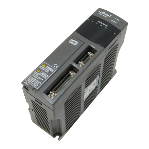
Higen FDA6000C Series user manual

Panasonic
Panasonic MHMD042P1C Technical reference
