TEC Electronics CANTEC-F2 User manual

18.12.2019
CAN
-
bus
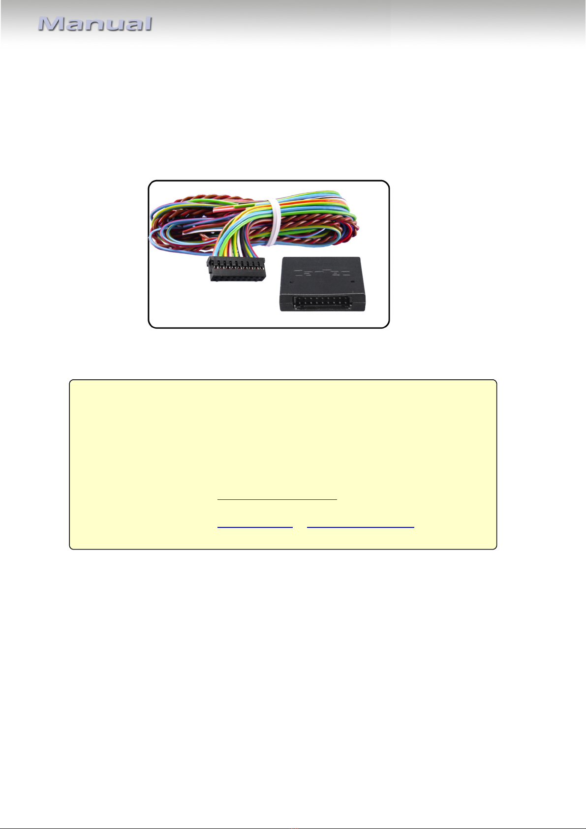
CAN-bus interface
CANTEC-F2
CAN-bus interface with USB-support for
analogue car-alarms, DC & more

CAN
-
bus
Contents
1. rior to installation
1.1. Delivery contents
1.2. Checking the compatibility of vehicle and function limitations
1.3. Planing programmable inputs and outputs
2. in definition and factory defaults of programmable outputs/inputs
3. Installation
3.1. Power and CA connections
3.2. Vehicle recognition
3.2.1. Automatic vehicle recognition
3.2.2. Forced vehicle recognition
3.3. Connections of programmable outputs/inputs
4. rogramming
4.1. Settings programming (ME U 1)
4.2. Programmable outputs/inputs configuration (ME U 2)
4.2.1. Programmable outputs (ME U 2 – options no. 1-12)
4.2.2. Programmable inputs (ME U 2 – options no. 13-16)
5. Reset to factory defaults
6. Specifications
7. Technical support
8. Customer-specific programmable output/input configuration (complete)
roduct features
CA TEC-F2 is a universal CA -bus interface, hereafter referred to as unit, designed for
connecting after-market car-alarm security, park-distance control, multimedia and service
systems to vehicles with CA -bus. The Unit has a build in micro USB port for easy
programming with TECprog Software.
The unit has ten programmable outputs, two of which have changeable polarity. 24 different
output functions are available (see chapter 4.2.1., available programmable outputs functions
– table 4). Four programmable inputs are designed for controlling vehicle devices. 9 different
input functions are available (see chapter 4.2.2., available programmable inputs functions –
table 6).
Vehicle recognition (model selection) is carried out automatically - for the majority of
vehicles after connecton, turning ignition on and off + vehicle locking/unlocking by original
remote control key.
CAN
-
bus
Requirements
Vehicle See CA TEC-F2 compatibility list at
Limitations
Vehicle-specific functions See CA TEC-F2 vehicle-specific installation files
and compatibility list
TECprog software look at: http://tecel.ru/en/tecprog/
Look for product info at www.navlinkz.de or www.canbus-alarm.com
1. rior to installation
Read the manual prior to installation.
Technical knowledge is necessary for installation. The place of installation must be free of
moisture and away from heat sources.
1.1. Delivery contents
1.2. Checking the compatibility of vehicle and function limitations
1.3. laning programmable inputs and outputs
It is strongly recommended to read the complete manual and to plan in advance, which of
the available programmable input and output functions are needed for the specific
installation (see chapter 4.2.). Maximum currents of the unit’s programmable inputs and
outputs must match connected devices’ power consumption.
It is possible to do most of the programming works with the TECprog software.
Please connect the Cantec Module with the Micro USB plug after you have installed the
Software from TEC website. It is not possible to setup the vehicle type of vehicles what are
newer than year 2017. This cars are almost not more listed in TECprog.
Please choose the automatic vehicle recognition (see 3.2.1) procedure for all cars – not
TECprog for this setup! Otherwise wrong CA connections will be not or bad detected.
early all other setup works for inputs outputs and user or hardware options are possible to
realize with TEC-prog. (For all compatible cars what are listed in integrator.)
CAN
-
bus
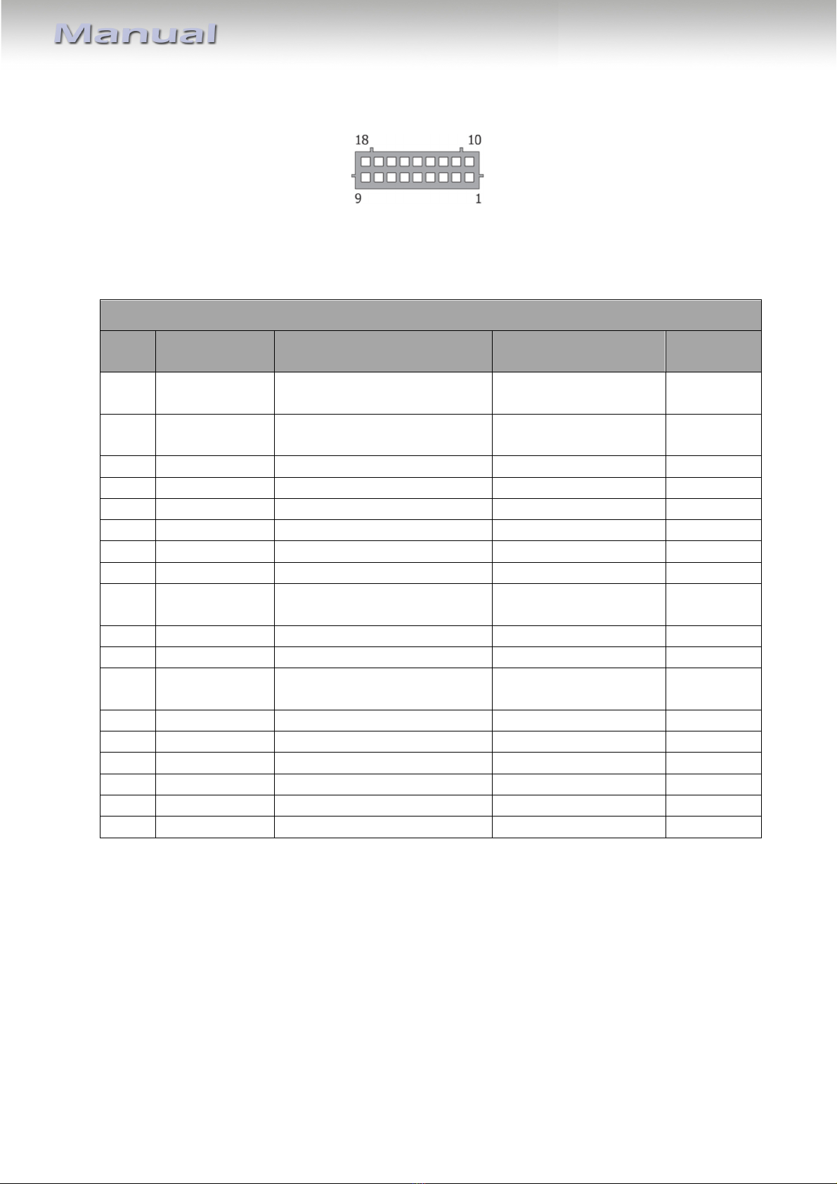
2. in definition and factory defaults of programmable outputs/inputs
Male pins of black-box 18pin port
Programmable outputs/inputs configuration can be done out via programming (see chapter
4.) or via TEC-PROG tool and software with Windows PC. Factory defaults are predefined
according to table 1. These settings can be restored by resetting the unit (see chapter 5.)
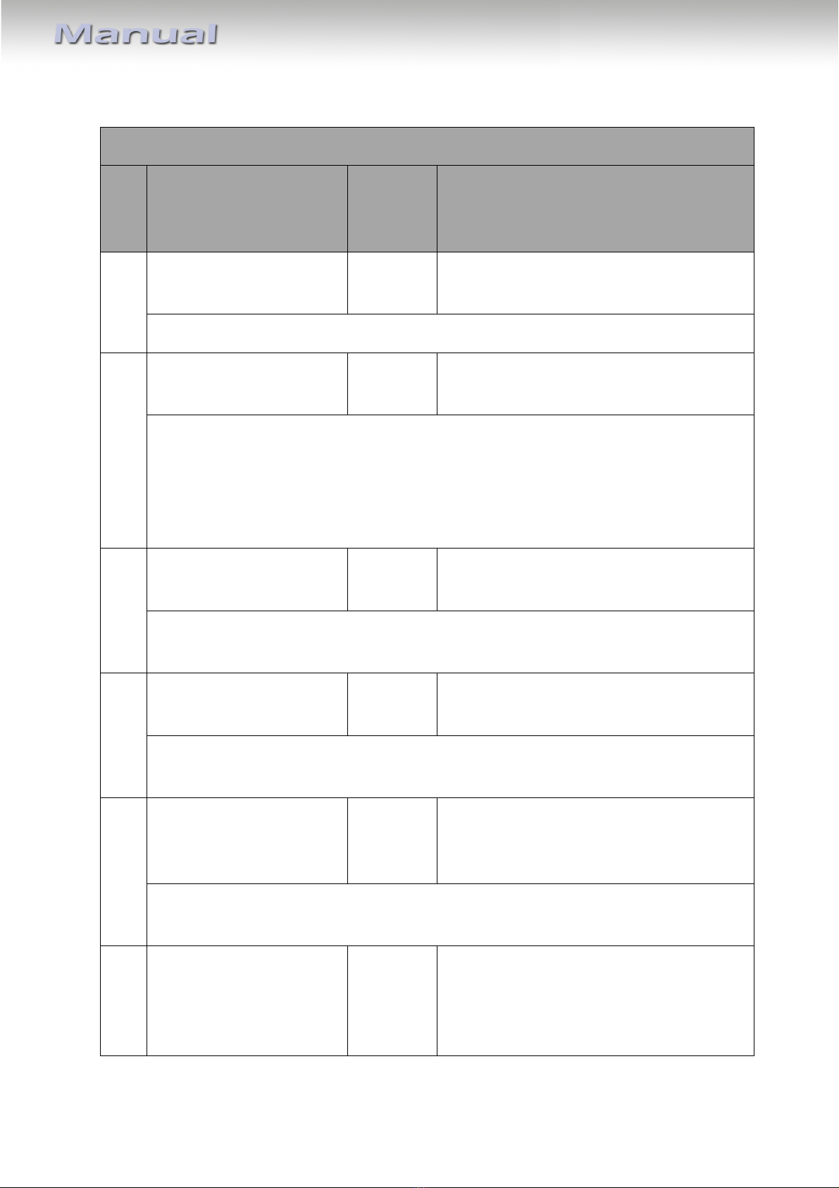
in definition and factory defaults of programmable outputs/inputs – table 1
in
no.
Harness wire
color Functionality Factory default
settings
Maximum
current
1 Blue/red Programmable output (+ / -)
with changeable polarity*
Front parking sensors
polarity +
200 mA
2 Blue/yellow Programmable output (+ / -)
with changeable polarity*
Back parking sensors
polarity +
200 mA
3 Black Ground of power supply - -**
4 White/black Programmable output (+) ACC 50 mA
5 Green/yellow Programmable output (-) Brake 50 mA
6 Pink/green Programmable output (+) Ignition 50 mA
7 Yellow/red Programmable output (+) PDC LED 50 mA
8 Green Programmable input (-) PDC control button 1.5 mA
9 Blue Programmable input (-) Unlock central door
locking
1.5 mA
10 Brown/red CA -high of vehicle data bus - -
11 Brown CA -low of vehicle data bus - -
12 Red +12V of power supply - 750 (4) mA
***
13 Gray/black Programmable output (-) Original buttons 50 mA
14 Gray/blue Programmable output (-) Car is moving 50 mA
15 Gray/green Programmable output (-) Parking brake 50 mA
16 Gray/yellow Programmable output (-) Speed 50 mA
17 Orange/white Programmable input (+) Hazard light control 1.5 mA
18 Orange/green Programmable input (-) Trunk opening 1.5 mA
* Outputs with changeable polarity. Outputs’ operation with load higher than the indicated
is not guaranteed and may damage the unit.
** Consumed current of output pin 3 depends on the load connected to all negative outputs.
*** Typical current rate is indicated for operation and standby modes. It may change
depending on positive outputs’ load.
Avoid making contact between ground and outputs pins 4, 6, 7 or +12V and outputs pins 5,
13-16. Otherwise the unit is damaged.

CAN
-
bus
3. Installation
3.1. ower and CAN connections
Disconnect the vehicle’s battery during installation or changes on the wiring!
Connect +12V, Ground, CA -high and CA -low wires of the unit’s harness to the
corresponding wires of the vehicle (see vehicle-specific installation file).
Connect the unit’s black-box to its harness and make sure that all other open end wires of
the harness do not short-circuit.
3.2. Vehicle recognition
For proper operation, the unit must recognize the vehicle and its specific CA -bus, thus
vehicle group and sub-group. There are two ways:
3.2.1. Automatic vehicle recognition
After installing the unit to power and CA -bus, by carrying out a set of simple actions (see
vehicle-specific installation file for procedure) the vehicle-specific group and sub-group are
defined automatically. To check correctness of group and sub-group the LED issues a number
of light signals (group number – pause, sub-group – pause).
If the unit identifies both vehicle group and sub-group, it emits triple series of light signals,
where the number of long signals corresponds with the group number, while the number of
short signals corresponds with the sub-group number.
If the unit identifies only the vehicle group, it stops emitting short light signals and
periodically emits series of lights signals, where the number of signals corresponds with
vehicle group.

CAN
-
bus
3.2.2. Forced vehicle recognition
Forced vehicle recognition is only to be executed in exceptional cases, when automatic
vehicle recognition has failed.
Programming is carried out via programming button and LED
indicator, which are located in the unit’s body. Prior to forced
vehicle recognition, the vehicle group previously must not
have been identified (if the vehicle group has previously
already been identified, a factory reset is necessary) and the
CA -bus must not be connected. Programming stops if the
programming button is not pressed within 60 seconds.
Programming sequence of forced vehicle recognition:
1. Connect the unit to power only and wait for permanent short fast light signals.
2. Press and release the programming button 10 times (begin this action not later than
10 seconds upon connecting the power source to the unit). If all the actions are
carried out correctly, the unit confirms with three light signals.
3. Enter option o. 1 – forced vehicle recognition (see table 2, chapter 4.1.) – by
pressing the programming button 1 time. The unit confirms the selection with
repeated single light signals.
4. Enter vehicle group number by pressing the programming button for the
corresponding number of times (see vehicle-specific installation file for group
number). The unit periodically emits series of light signals, where the number of
signals corresponds with the entered group number.
5. Wait at least 2 seconds.
6. Enter the vehicle sub-group number by pressing the programming button for the
corresponding number of times (see vehicle-specific installation file for sub-group
number). Check if the vehicle model has been chosen correctly. The unit emits light
signals (group number – pause, sub-group number – pause):
•If the vehicle model is chosen correctly, press the programming button once.
Light signals stop and the vehicle model is saved.
•If the vehicle model has been chosen incorrectly, press the programming
button twice. Repeat the programming beginning from point 4.
7. Reconnect unit to CA -bus.
3.3. Connections of programmable outputs/inputs
After successful vehicle recognition disconnect the unit’s black-box from its harness.
Connect all the input and output wires to the corresponding places. Make sure that
unneeded output/input wires are isolated.

CAN
-
bus
4. rogramming
All programming is done by the unit’s programming button, LED and the vehicle’s brake
pedal. The unit’s settings and input/output functions can be changed or checked in two
menus after entering their programming modes. In ME U 1 it is possible to change settings
– activate/deactivate functions, or change values or algorithms of functions (see chapter
4.1.). In ME U 2, the functions which shall be used on the unit’s programmable outputs (see
chapter 4.2.1.) and on the programmable inputs (see chapter 4.2.2.) can be defined.
4.1. Settings programming (MENU 1)
Follow the below programming sequence to change or check settings of ME U 1:
1. Turn on ignition.
2. To enter ME U 1, press the programming button 10 times. The unit confirms with
three light signals.
3. After selecting the option desired from table 2, to change or check its status, press
the programming button for the number of times corresponding with the option
number (no.). The unit confirms with the same number of light signals.
4. To enter the programming mode, press and hold the brake pedal*. The unit informs
about the status of the chosen option by the corresponding number of LED light
signals. There is no countdown until programming mode is deactivated.
5. Change the option’s setting value (exception: option no. 9 – PDC control button - see
table 2 instead**) by pressing the programming button for the number of times
required to move from current setting to the required setting value while the last
setting value is followed by the first one. (e.g., in order to change option no. 5
(comfort timer channel) from setting value 3 to 1, press the programming button 4
times). The unit confirms new the setting value with the corresponding amount of
light signals.
6. Release the brake pedal. The unit’s light indication changes from option setting back
to option number. It is possible to proceed with programming the next option or to
leave the programming mode.
7. Move to next option’s programming by pressing the programming button for the
number of times required to navigate from current option’s number to the required
option’s number while the last option’s number is followed by the first one.
8. The unit leaves the programming mode and saves all settings in permanent memory,
60 seconds after last action if brake is not pressed or when ignition is switched off.
*Note – If the vehicle’s brake pedal is not visible on CA -bus (see vehicle-specific installation
file), the unit’s trunk opening input is used (G D impulse instead of brake pedal press).
CAN
-
bus
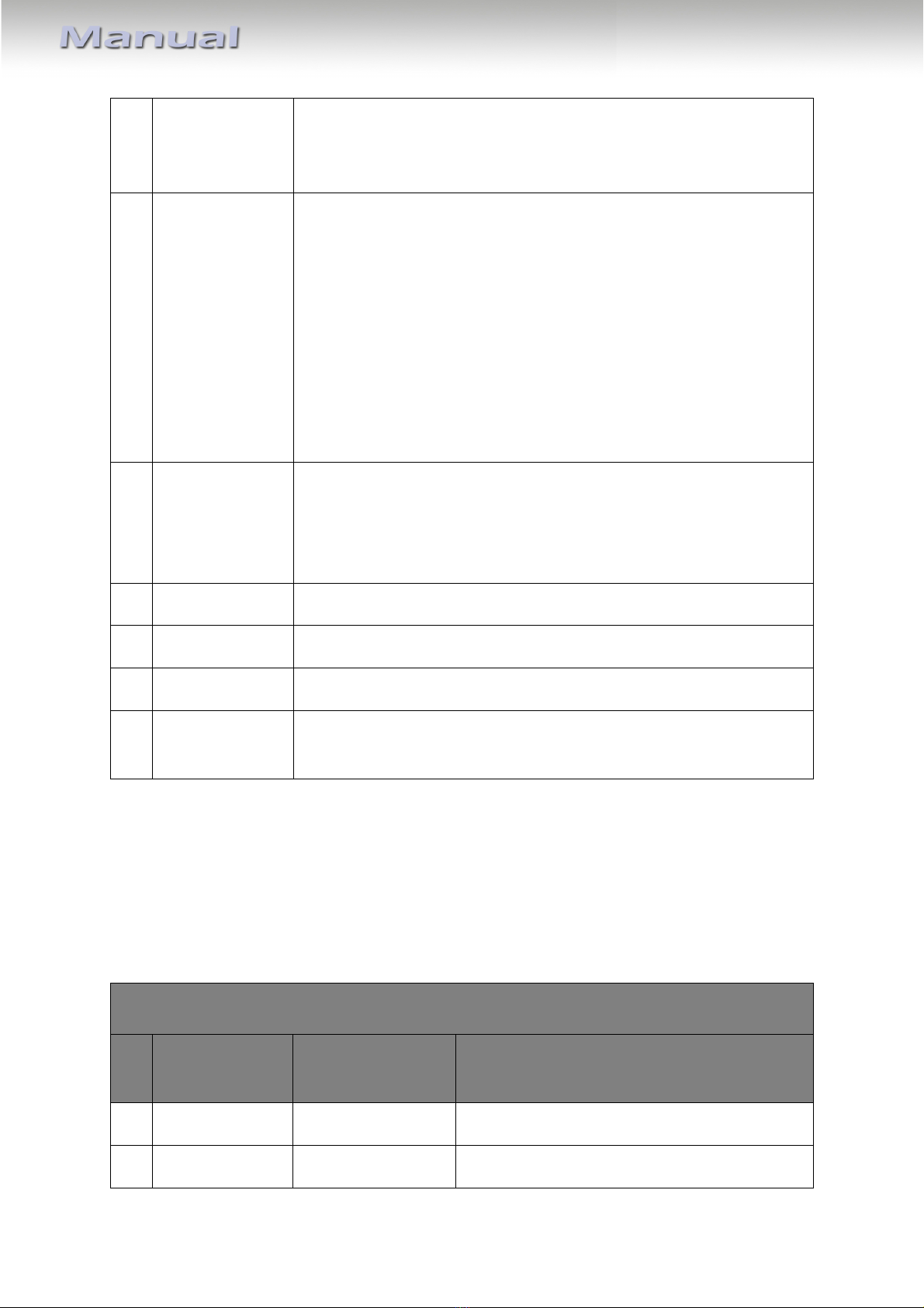
Settings (MENU 1) – table2
no. Option description
Setting
range/
default
LED signals, notes
1 Forced vehicle recognition - / - See chapter 3.2.2. Forced vehicle
recognition
Forced vehicle group and sub-group assignment, when automatic has not worked.
2 Original car alarm control -/disabled LED is on – factory car alarm control is on
LED is off – factory car alarm control is off
If O , the unit locks and unlocks the vehicle with the same commands that activate
(deactivate) the original alarm system (via original remote control, door lock etc.). If
OFF, the unit locks (unlocks) the vehicle with commands that don’t activate
(deactivate) the original alarm system. (E.g. central lock locking/unlocking via vehicle
interior button).
3 Sequential door opening -/disabled LED is on – the function is on
LED is off – the function is off
Activating or deactivating the sequential door opening. If activated upon one
unlocking command only driver’s door is unlocked, after two commands all doors.
4 Automatic windows
closing (comfort feature)
-/disabled LED is on – the function is on
LED is off – the function is off
Activating or deactivating automatic windows closing comfort feature when using the
central lock. If O , 2 seconds after central locking the unit will close the windows.
5 Comfort timer channel
function operation length
– output function no. 24
1-6 / 3 One LED signal per 10 seconds
Time during which timer channel (comfort) function stays active. Set in 10-second
intervals.
6 Central locking alternative
control algorithm of
output pin 2
1-3/- 1 – impulse negative control
2 – impulse positive control
3 – impulse negative control (when central
locking status is not available)

CAN
-
bus
In most cases the algorithm and polarity are set automatically when recognizing the
vehicle.
7 Hazard lights alternative
control algorithm of
output pin 1
1-5 / - 1 – impulse negative control
2 – status negative control
3 – impulse positive control
4 – status positive control
5 – lamps control (negative)
In the majority of cases the algorithm is set automatically when recognizing the
vehicle.
8 Parking distance control
(PDC) system algorithm –
output functions no. 17-19
1-3/1 1 – “Activation on rear gear”
2 – “Activation on speed”
3 – “Activation on rear gear with priority of
switching off”
“Activation on rear gear” - Front and rear parking sensors are activated when reverse
gear is engaged or by PDC control button (see option no. 9). Deactivation upon speed
reaches 15km/h or by PDC control button.
“Activation on speed” - Front parking sensors are active as long as the vehicle’s speed
is less than 15km/h. Rear parking sensors are active if the vehicle moves back and its
speed is less than 15km/h. Activation (when speed < 15km/h) and deactivation
possible by PDC control button. Automatic (re-)activation on ignition on.
“Activation on rear gear with priority of switching off”. Same algorithm as
“Activation on rear gear”, but if parking sensors have been deactivated by PDC control
button no automatic activation on engaged reverse gear until next ignition on or
activation by PDC control button.
9 PDC control button –
output functions no. 17-19
-/- Any OEM (factory) vehicle’s button which is
“visible” in CA -bus can be used. Also any
(negative/positive) button connected to the
corresponding output of the unit. Also the
length of control press can be determined.
PDC control button assigning algorithm. Press and hold the button that you have
chosen as PDC button for the particular time:
•Control with short press – keep button pressed less than 2 seconds
•Control with long press (2.5 sec) – keep button pressed 3-5 seconds
•Control by status (on/off) – keep the button pressed longer than 5 seconds
The LED light is off while the button press is detected. Release the button. The unit
emits one light signal and turns off. 6. of programming sequence (chapter 4.1.)

CAN
-
bus
4.2. rogrammable outputs/inputs configuration (MENU 2)
In ME U 2, the programmable outputs and inputs can be set to other functions than the
predefined factory defaults (see chapter 2.).
Follow the below programming sequence to change or check programmable output/input
functions of ME U 2:
1. Turn on ignition.
2. To enter ME U 2, press the programming button 12 times. The unit confirms with
four light signals.
3. After selecting the programmable output’s/input’s option no. desired to
change/check (see chapters 4.2.1. or 4.2.2., tables 3 or 5), press the programming
button for the number of times corresponding with the option number (no.). The unit
confirms with the same amount of light signals.
4. To enter the programming mode, press and hold the brake pedal*. The unit informs
about the status of the chosen option by the corresponding number of LED light
signals. There is no countdown until programming mode is deactivated.
5. Change the option’s function no. by pressing the programming button for the
number of times required to move from current setting to the required setting value
while the last setting value is followed by the first one. (e.g., in order to change
option no. 5 (positive output – pin 4) from factory default function no. 13 - engine on
to function no. 21 - brake, press the programming button 8 times). The unit confirms
new the setting value with the corresponding number of light signals.
6. Exceptions: programmable output functions no. 8 10 and 15 require additional
programming sub-sequence see corresponding function no. in table 4.
7. Release the brake pedal. The unit’s light indication changes from option setting value
back to option number. It is possible to proceed with programming the next option
or to leave the programming mode.
8. Move to next option’s programming by pressing the programming button for the
number of times required to navigate from current option’s number to the required
option’s number while the last option’s number is followed by the first one.
9. The unit leaves the programming mode, and saves all settings in permanent memory,
60 seconds after last action if brake is not pressed or when ignition is switched off.
*Note – If the vehicle’s brake pedal is not visible on CA -bus (see vehicle-specific installation
file), the unit’s trunk opening input is used (G D impulse instead of brake pedal press).
4.2.1. rogrammable outputs (MENU 2 – options no. 1-12)
Pin 1 and 2 are, if necessary for this vehicle, preset to alternate hazard lights control and
alternate central locking control, including the required polarity (see vehicle-specific
installation file). If alternate hazard lights control and alternate central locking control are
not necessary, both pins are programmable (max. 200mA) with changeable polarity. When

CAN
-
bus
assigning any of the available output functions to these two programmable outputs, it is
necessary to set the required polarity.
All other outputs are generally programmable and can be changed from their factory
defaults (see chapter 2. - table 1) to any other available output function (see chapter 4.2.1.,
table 4) with max. 50mA. It is possible to use the same function for more than one output.
It is possible to enter the from table 4 chosen output function for each programmable
output into below table 3.
rogrammable outputs configuration (MENU 2) – table 3
no.
Option
description
Setting range
/ default
Notes (enter programmed/planned output
functions from table 4)
1 Output (+/-) pin 1 (1-24) / 17 Front parking sensors turning on
2 Output pin 1
polarity
+ / positive
polarity
LED is on – positive
LED is off – negative
3 Output (+/-) pin 2 (1-24) / 18 Rear parking sensors turning on
4 Output pin 2
polarity
+/ Positive
polarity
LED is on – positive
LED is off – negative
5 Output (+) pin 4 1-24/12 ACC
6 Output (-) pin 5 1-24/21 Brake
7 Output (+) pin 6 1-24/11 Ignition
8 Output (+) pin 7 1-24/19 PDC LED
9 Output (-) pin 13 1-24/10 Original buttons
10 Output (-) pin 14 1-24/16 Car is moving
11 Output (-) pin 15 1-24/22 Parking brake
12 Output (-) pin 16 1-24/20 Speed
The setting range 1-24 in table 3, equals the available programmable output functions from
table 4.
Output functions no. 8, 10 and 15 have sub-settings for which the sub-sequences to chapter
4.2. are also described in table 4.

CAN
-
bus
Available programmable output functions – table 4
no.
Function Function description
1 Security Constant level signal while the unit is in Secure mode.
2 Arming impulse 0.8 sec long impulse when the unit is armed.
3 Disarming
impulse
0.8 sec long impulse when the unit is disarmed.
4 Trunk opening
via original
remote control
impulse
0.8 sec long impulse on trunk opening command of original
remote control.
5 Original alarm
system panic
Constant level signal while original alarm system (if one is
installed) is in alert mode.
6 Siren panic 30 sec long constant level signal when one of the zones is
triggered in security mode: trunk, doors, hood opening. This
function can be used in vehicles that are not equipped with an
original alarm system. The signal stops when the vehicle leaves
security mode.
7 Panic on horn
from external
input
Impulse signal while there is an input signal on a programmable
input which is defined as horn control.
8 Doors, hood
and trunk
Constant level signal when any of the preprogrammed doors,
hood or trunk is open.
Programming sub-sequence: Any combination of doors, hood and trunk opening can
be chosen to trigger this programmable output. For purpose of description, the
doors, hood and trunk is below referred to as doors. Release brake. Open only doors
that are supposed to be indicated by this output, keep the rest closed (doors can be
open in advance). Press the brake again. The unit confirms with series of 8 light
signals and the open doors are be assigned as trigger(s) to this output. If the brake is
not pressed, the previous assignment stays saved. After releasing the brake, the unit
starts indicating the option’s no. 8. of programming sequence (chapter 4.2.).
9 Sensors ignoring
Constant level signal while in security mode with the trunk open if
it is opened with original remote control. Also the signal is formed
for the time while comfort feature is active. This function is
designed for organizing sensors’ deactivation in order to evade
false alarms.

CAN
-
bus
10 Original buttons Constant level signal when a preprogrammed vehicle button is
pressed.
Programming sub-sequence: Without releasing the brake, press desired button (see
vehicle specific installation file for visible buttons). Upon button identification, the
unit stops emitting short light signals and emits series of 10 light signals. If brake is
released prior to identification, the previous assignment stays saved. After releasing
brake, the unit starts indicating the option’s no. 8. of programming sequence
(chapter 4.2.).
11 Ignition Constant level signal while ignition is on (including engine start).
12 ACC Constant level signal while vehicle ACC is on (first key position,
may be congruent with ignition in some vehicles). Deactivation
when the key is removed from the ignition lock. Can be used as
accessory power supply for multimedia systems.
13 Engine on Constant level signal while engine is on.
14 Engine rpm Impulse signal with impulse sequence frequency proportionate to
vehicle crank rotation frequency. 1 impulse/sec corresponds with
crank rotation frequency of 20rpm. Signal is designed for
determining estimated, but not the exact rpm.
15 Transmission
condition
Constant level signal when the transmission is set to
preprogrammed gear (P, R, , D). For robotized transmissions the
following gears can be programmed: R, , D). For manual
transmissions only R gear is available.
Programming sub-sequence: Without releasing the brake, set the transmission to
required gear: P, , D or R. Release and press the brake again. The unit stops
emitting short light signals and indicates option setting number with series of 15
light signals. If the brake is not pressed, the previous assignment stays saved. After
releasing the brake, the unit starts indicating the option’s no. 8. of programming
sequence (chapter 4.2.).
16 Vehicle moving Constant level signal while the vehicle speed has exceeded a
certain threshold rate (varies from vehicle to vehicle but within 5-
10km/h).
17 Front parking
sensors
activation
Constant level signal for front-parking sensors activation
according to algorithm chosen in ME U1 (table 2), no. 8
CAN
-
bus
18 Rear parking
sensors
activation
Constant level signal for rear-parking sensors activation according
to algorithm chosen in ME U1 (table 2), no. 8
19 Parking distance
control LED
indicator
Indicator the PDC system condition.
•If parking sensors work according to “Activation on rear
gear” or “Activation on rear gear with priority of switching
off “ algorithm, LED indicator is O when the sensors are
active
•If parking sensors works according to “Activation on
speed” or “Activation on rear gear with priority of
switching off “ algorithm, LED indicator is OFF when the
sensors are not active
20 Speed Impulse signal with impulse sequence frequency proportionate
with vehicle movement speed. 1 imp/sec corresponds with 1km/h
speed. This signal is designed for determining estimated but not
the exact speed.
21 Brake Constant level signal when the brake pedal is pressed.
22 Parking brake Constant level signal when parking brake is activated.
23 Parking lights Constant level signal when the external lights are activated.
24 Comfort timer
channel
Constant level signal during a certain time period (from 10 to 60
seconds) after arming the vehicle. The time is set in units of 10sec.
4.2.2. rogrammable inputs (MENU 2 – options no. 13-16)
All other inputs are generally programmable and can be changed from factory defaults (see
chapter 2., table 1) to available input functions (see chapter 4.2.2., table 5) with max. 50mA.
It is possible to enter the from table 6 chosen input function for each programmable input
into below table 5.
rogrammable inputs configuration (MENU 2) – table 5
no.
Option
description
Setting range /
default
Notes (enter programmed/planned output
functions from table 6)
13 Input (-) pin 8 1-9/9 PDC control button
14 Input (-) pin 9 1-9/2 Unlock central door locking
CAN
-
bus
15 Input (+) pin 17 1-9/4 Hazard lights control
16 Input (-) pin 18 1-9/3 Unlock trunk
The setting range 1-9 in table 5, equals the available programmable input functions from
table 6.
Available programmable inputs functions – table 6
no.
Function Function description
1 Central locking
+ Comfort
Trigger input (impulse) for central locking. When input signal is >2
seconds, windows comfort closing is started. Windows’ closing
stops when the signal stops. CA -bus or alternate.
2 Central
unlocking
Trigger input (impulse) for central unlocking. CA -bus or
alternate.
3 Trunk opening Trigger input (impulse) for s opening the trunk lid via CA -bus.
4 Hazard lights
activation
Trigger input (impulse) for hazard lights, one flash per impulse. On
some vehicles, uneven lamp blinking may be observed while the
impulses are fed evenly. CA -bus or alternate.
5 Horn control Trigger input (constant) activates the programmable output
function no. 7 – “panic on horn from external input”. Sound
output in intervals. Stopping the input feed stops this function.
6 Engine start Engine starts via CA -bus (only some Cadillac, Chevrolet,
Hummer).
7 Central lock is
locked (status)
Trigger input (constant) to provide “locked” status in vehicles
where it is not available on CA -bus (see vehicle-specific
installation file).
8 Central lock is
unlocked
(status)
Trigger input (constant) to provide “unlocked” status in vehicles
where it is not available on CA -bus (see vehicle-specific
installation file).
9 PDC control
button
Used for providing control of PDC (parking distance control) with
optional external button (required when no “visible” CA -bus
buttons available).

CAN
-
bus
5. Reset to factory defaults
By hardware reset, all programmable settings and functions of the unit are restored to factory
default and the vehicle recognition (group and sub-group) is erased. To restore factory defaults:
•Detach the unit from power source and CA -bus.
•Press and hold the programming button.
•With the programming button pressed, supply power to the unit (CA -bus must remain
disconnected). The unit emits permanently short fast light signals.
•Detach the power source and release the programming button.
6. Specifications
BATT/ACC range 9V ~ 15V
Stand-by power drain <4mA
Power consumption 9W
Temperature range -40°C to +85°C
Weight (box with harness) 45g
Dimensions (box only) B x H x T 30 x 30 x 7 mm
7. Technical Support
NavLinkz GmbH TEC electronics ltd
EU-distribution and tech dealer-support manufacturer
Eurotec-Ring 45 16th Parkovaya 30, Bld.1
D-47445 Moers 105484 Moscow, Russia
Tel +49 2841 94997 0
Email [email protected]
http://www.navlinkz.de http://www.canbus-alarm.com

CAN
-
bus
8. Customer-specific programmable output/input configuration (complete)
For reason of better comprehension, in chapter 4.2., programmable outputs and inputs are
separated. Full configuration can be noted in the below table. For support reasons, we also
suggest to apply the extra serial number sticker in CA TEC-F2 box here:
________________
in definition and customer-specific outputs/inputs configuration
in
no.
Harness wire
color Functionality Factory default
settings
Maximum
current
1 Blue/red Programmable output (+ / -)
with changeable polarity*
200 mA
2 Blue/yellow Programmable output (+ / -)
with changeable polarity*
200 mA
3 Black Ground of power supply reserved
4 White/black Programmable output (+) 50 mA
5 Green/yellow Programmable output (-) 50 mA
6 Pink/green Programmable output (+) 50 mA
7 Yellow/red Programmable output (+) 50 mA
8 Green Programmable input (-) 1.5 mA
9 Blue Programmable input (-) 1.5 mA
10 Brown/red CA -high of vehicle data
bus
reserved
11 Brown CA -low of vehicle data bus reserved
12 Red +12V of power supply reserved
13 Gray/black Programmable output (-) 50 mA
14 Gray/blue Programmable output (-) 50 mA
15 Gray/green Programmable output (-) 50 mA
16 Gray/yellow Programmable output (-) 50 mA
17 Orange/white Programmable input (+) 1.5 mA
18 Orange/green Programmable input (-) 1.5 mA
Table of contents
Other TEC Electronics Automobile Accessories manuals

Popular Automobile Accessories manuals by other brands


ULTIMATE SPEED
ULTIMATE SPEED 279746 Assembly and Safety Advice

SSV Works
SSV Works DF-F65 manual

ULTIMATE SPEED
ULTIMATE SPEED CARBON Assembly and Safety Advice

Witter
Witter F174 Fitting instructions

WeatherTech
WeatherTech No-Drill installation instructions

TAUBENREUTHER
TAUBENREUTHER 1-336050 Installation instruction