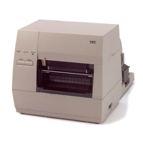
TEC CB-416 Series User manual

PRINTED IN JAPAN
TEC Color Printer
CB-416/426-T3 SERIES
Original Aug., 1998
(Revised Mar., 1999)
Document No. EO18-33002A
Maintenance Manual

TABLE OF CONTENTS
1. UNPACKING ...........................................................................................1- 1
1.1 PROCEDURE..................................................................................1- 1
1.2 CHECKS..........................................................................................1- 2
2. MAIN UNIT REPLACEMENT ..................................................................2- 1
2.1 REPLACING THE CPU PC BOARD ...............................................2- 2
2.2 REPLACING HCHK PC BOARD.....................................................2- 3
2.3 REPLACING THE DRIVER PC BOARD .........................................2- 4
2.4 REPLACING HWC PC BOARD ......................................................2- 6
2.5 REPLACING PDM PC BOARD .......................................................2- 7
2.6 REPLACING THE PS UNIT ............................................................2- 8
2.7 REPLACING THE PLATEN MOTOR AND FEED MOTOR.............2- 9
2.8 REPLACING THE RIBBON MOTOR ASS'Y ...................................2-10
2.9 REPLACING THE SOLENOID ASS'Y.............................................2-11
2.10 REPLACING THE PRINT HEAD.....................................................2-12
2.11 REPLACING THE PLATEN AND MEDIA SENSOR .......................2-13
2.12 REPLACING THE PINCH ROLLER ASS'Y.....................................2-14
2.13 DIP SWITCH SETTINGS ................................................................2-15
3. INSTALLATION PROCEDURE FOR OPTIONAL EQUIPMENT ............3- 1
3.1 CUTTER MODULE (CB-1204-QM) .................................................3- 1
3.2 RIBBON MODULE (CB-1004-QM)..................................................3- 3
3.3 PRINT HEAD FAN...........................................................................3- 5
4. TROUBLESHOOTING.............................................................................4- 1
5. DIAG. TEST OPERATION.......................................................................5- 1
5.1 OUTLINE OF THE DIAG. TEST OPERATION................................5- 1
5.2 SELF TEST MODE..........................................................................5- 2
5.3 PARAMETER SETTING MODE......................................................5-10
5.4 TEST PRINT MODE........................................................................5-43
5.5 RAM CLEAR MODE........................................................................5-51
6. PROGRAM DOWNLOAD........................................................................6- 1
6.1 FLOPPY DISK .................................................................................6- 1
6.2 SETUP.............................................................................................6- 1
6.3 OUTLINE OF THE PROGRAM DOWNLOAD PROCEDURE .........6- 1
6.4 DOWNLOAD PROCEDURE ...........................................................6- 1
EO18-33002A
(Revision Date: Dec. 20, 2000)
CAUTION:
1. This manual may not be copied in whole or in part without prior written permission of TOSHIBA
TEC.
2. The contents of this manual may be changed without notification.
3. Please refer to your local Authorized Service representative with regard to any queries you may
have in this manual.
Page
Copyright © 2000
by TOSHIBA TEC CORPORATION
All Rights Reserved
570 Ohito, Ohito-cho, Tagata-gun, Shizuoka-ken, JAPAN
1-1
1. UNPACKING EO18-33002A
1.1 PROCEDURE
1. UNPACKING
1.1 PROCEDURE
1) Open the carton.
2) Unpack the accessories from the carton.
3) Unpack the printer and remove the side pads (L) and (R).
4) Place the printer on a level surface.
Media Side Black Screw
Partition
Supply Roll Holder Pad (L)
Supply Roll Holder
Supply Roll Holder Pad (R)
Carton
Carton
Side Pad (R)
Band
Owner's Manual
Power Cord
Fan Filter
Feed Roller Brush
Print Head Cleaner
Side Pad (L)
Printer Rear Pad
Bottom Pad
Fig. 1-1

1-2
1. UNPACKING EO18-33002A
1.2 CHECKS
6) Remove the six pieces of tape to open the top cover and remove the rear pad.
7) Remove the 12 pieces of tape from the internal parts.
8) Turnallof the headleversto the OPENpositionto open the pinchroller ass'y and removethesheet
of paper protecting the print heads.
9) Turn all of the head levers to the LOCK position to close the pinch roller ass’y, then lower the pinch
roller lever to the ROLLER LOCK position.
10) Close the top cover.
NOTES: 1. Regarding attachment of the accessories, refer to the Owner's Manual.
2. The above illustration is for the CB-416-T3-QQ/QP model. Since the CB-426-T3-QQ/QP
model is a two-color printer, the two print head blocks to the right hand are not installed.
Please accept that all illustrations provided in this manual hereafter are for the CB-416-
T3-QQ/QP.
1.2 CHECKS
1) Check for damage or scratches on the machine.
2) Confirm that none of the accessories are missing.
NOTES: 1. Keep the cartons and pads for future transportation of the printer.
2. If the printer is to stand unused for a long period of time or if it is to be transported, be sure
to insert a sheet of paper under all the print heads and the pinch roller to protect the print
heads.
Tape
Tape
Tape Rear Pad
Fig. 1-2
Tape Tape Pinch Roller Ass'y
Head Lever Tape
Tape
Pinch Roller Lever
Fig. 1-3
Pinch Roller
CB-416: Print Head (Yellow)
CB-426: 2nd Print Head
CB-416: Print Head (Cyan)
CB-426: 1st Print Head
CB-416: Print Head (Magenta)
CB-426: Not installed CB-416: Print Head (Black)
CB-426: Not installed

2-1
2. MAIN UNIT REPLACEMENT EO18-33002A
2. MAIN UNIT REPLACEMENT
CAUTION:
Never remove the red screws. Doing so will change the adjustment.
1) Turn the power off.
2) Open the top cover and remove all of the ribbon module.
3) Remove the four B-3x6 screws and five B-4x6 screws securing the left side cover, detach the fan
motor connectors (CN3 and CN4) then remove the left side cover.
4) Remove the two B-4x6 screws securing the operation panel and disconnect the CN40 and CN51
connectors from the driver PC board, then remove the operation panel.
NOTE: Instructionsforopeningthetop coverandremovingtheleftsidecoverandoperationpanelare
omitted from each removal/installation procedure provided below.
CAUTION:
1. Lubrication: During parts replacement
2. Kinds of oil: FLOIL G-488: 1Kg can. (Part No. 19454906001)
3. Donotspraytheinside oftheprinterwithlubricants. Unsuitableoilcandamagethemechanism.
All machines are generally delivered in their best condition. Efforts should be made to keep them that
way. Lack of oil, or the presence of debris or dust, may cause an unexpected failure. To maintain in
optimaloperationcondition,periodicallyclean themachineand applytheproperkindsof oiltoeach part
in which lubrication is needed.
Although the frequency of lubrication varies according to how often the machine is used, as a minimum
it is necessary to lubricate before any part becomes dry. It is also necessary to wipe off excessive oil
or it will collect dirt.
WARNING!
Disconnect the power cord before replacing the main parts.
LUBRICATION
Left Side Cover Top Cover
B-3x6 Screw
Operation Panel
B-4x6 Screw
Fan Motor
B-4x6 Screw
B-4x6 Screw Fig. 2-1

2-2
2. MAIN UNIT REPLACEMENT EO18-33002A
2.1 REPLACING THE CPU PC BOARD
1) Disconnect all connectors from the CPU PC board.
2) Remove the three SMW-3x6 screws (small washer type) and four SMW-3x6.
3) Remove the CPU PC board from the driver PC board.
4) Replace the CPU PC board with a new one, and then reassemble in the reverse order of removal.
Refer to the following DIP SW function table and set the serial interface specifications.
CPU PC Board Fig. 2-2
DIP SW SMW-3x6
Screw
SMW-3x6 Screw
(Small Washer Type)
SMW-3x6
Screw
NOTE: The shaded settings are the factory default settings. "OFF" means "OPEN".
■DIP SW
This DIP switch is provided on the CPU PC board. Even after installing the CPU PC board, it is
accessible from the rear of the printer by removing the DIP SW cover.
.oNFFO/NOnoitcnuF
1
2
12
deepsnoissimsnarT
FFOFFOSPB0042
NOFFOSPB0084
FFO NO SPB0069
NONOSPB00291
3FFO tib1 htgneltibpotS
NOstib2
4FFOstib7 htgnelataD
NO stib8
5FFO tuohtiW kcehcytiraP
NO htiW
6FFO NEVE PIDnehwevitceffe(kcehcytiraP ).NOottessi5#WS
NODDO
7
8
78
locotorpataD
FFOFFO ).emitnorewopehttatuptuosiNOXoN(FFOX/NOX ).emitfforewopehttatuptuosiFFOXoN(
NOFFO )ATD(YSUB/YDAER ).emitnorewopehttatuptuosiNOXoN( ).emitfforewopehttatuptuosiFFOXoN(
FFO NO YSUB/YDAER+FFOX/NOX ).emitnorewopehttatuptuosiNOX( ).emitfforewopehttatuptuosiFFOX(
NONO).emitnorewopehttatuptuosiNOX(FFOX/NOX ).emitfforewopehttatuptuosiFFOX(

2-3
2. MAIN UNIT REPLACEMENT EO18-33002A
2.2 REPLACING THE HCHK PC BOARD
1) Remove the SMW-3x6 screw from the HCHK PC board.
2) Release the HCHK PC board from the locking support.
Locking Support
Fig. 2-3
3) Replace the HCHK PC board with a new one, and then reassemble in the reverse order of removal.
SMW-3x6 Screw
Driver PC Boared
HCHK PC Board

2-4
2. MAIN UNIT REPLACEMENT EO18-33002A
2.3 REPLACING THE DRIVER PC BOARD
1) Remove the CPU PC board. (See Section 2.1.)
2) Disconnect all connectors from the driver PC board.
3) Remove the four SMW-4x8 screws to detach the driver PC board from the printer.
4) AfterreplacingthedriverPCboardwithanewone,refertothefollowing[CHECK]and[ADJUSTMENT]
and reassemble in the reverse order of removal.
1. Set the DIP switches on the new driver PC board. (Refer to Section 2.13.)
2. Firmly connect the harnesses with the connectors by matching their colors on the driver PC board.
1. After replacing the driver PC board, be sure to adjust the media sensor voltage following the
procedure described on the next page.
2. Refer to the Owner’s Manual to readjust the media sensor sensitivity.
2.3 REPLACING THE DRIVER PC BOARD
CHECK
ADJUSTMENT
Fig. 2-4
SMW-4x8 Screw
SMW-4x8 Screw
WARNING!
Replace only with the same type and rated fuse for continued protection against risk of fire.
Driver PC Board

2-5
2. MAIN UNIT REPLACEMENT EO18-33002A
■Adjusting the Media Sensor Voltage
After replacing the driver PC board, be sure to adjust the sensor voltage using the procedure below.
When adjusting the black mark sensor, place IJ16 tag paper (OSAKA SEALING) so that the sensor
can sense the print area of the tag paper. For the feed gap sensor adjustment, place IJKS labels
(OSAKA SEALING).
(1) Connect the printer to a PC and turn the power on for both.
(2) Adjust the media sensor voltage.
■Black Mark Sensor
Fully turn the feed gap sensor adjustment knob on the rear of the printer counterclockwise.
Turn the black mark sensor adjustment knob so that the notch stops at a 180 degree angle.
TurntheVR3on thedriverPCboardineitherdirectionuntilalltheblackmarksensor lampsare
lit. Ifthe lampsdo notlight,turn theblack marksensor adjustment knobwithin theanglerange
of 150 degree to 210 degree, and retry.
■Feed Gap Sensor
Fully turn the black mark sensor adjustment knob on the rear of the printer counterclockwise.
Turn the feed gap sensor adjustment knob so that the notch stops at a 90 degree angle.
Turn the VR4 on the driver PC board in either direction until the topmost feed gap sensor
lamp lights. If the lamp does not light, turn the feed gap sensor adjustment knob within the
angle range of 60 degree to 120 degree, and retry.
NOTE: Adjust the knobs so that they stop in the mid-range with all the lamps lit.
(3) After completing this procedure, turn the power off.
2.3 REPLACING THE DRIVER PC BOARD
ADJUSTMENT
GAP MARKER
VR4 VR3
IC22 CN10
IC23
IC24 CN11
TPGI
TPGR
B-CX DRIVER PWB
FMJD0004802
CN9
2 1
CN8
2 1.
33
Feed Gap Sensor Lamps
Black Mark Sensor Lamps
Green
Red
Notch
Black Mark Sensor Adjustment Knob
Feed Gap Sensor Adjustment Knob
Fig. 2-5
Driver PC Board Rear of the Printer
Fig. 2-6
Fig. 2-7
150°
210°
180°
120°
60°90°
GAP
GAP
MARK
MARK
VR3
VR4
MARK
GAP

2-6
2. MAIN UNIT REPLACEMENT EO18-33002A
2.4 REPLACING THE HWC PC BOARD
1) Remove the CPU PC board. (See Section 2.1.)
2) Remove the driver PC board. (See Section 2.3.)
3) Disconnect all cables from the HWC PC board.
4) Remove the three SMW-3x6 screws (small washer type) and two SMW-3x6 screws to detach the
HWC PC board from the driver PC board.
Fig. 2-8
HWC PC Board
5) Replace the HWC PC board with a new one, and then reassemble in the reverse order of removal.
SMW-3x6 Screw
(Small Washer Type)
SMW-3x6 Screw

2-7
2. MAIN UNIT REPLACEMENT EO18-33002A
2.5 REPLACING THE PDM PC BOARD
1) Disconnect all cables from the PDM PC board.
2) Remove the four SMW-3x6 screws to detach the PDM PC board.
Fig. 2-9
PDM PC Board
2.5 REPLACING THE PDM PC BOARD
SMW-3x6 Screw
SMW-3x6 Screw
3) Replace the PDM PC board with a new one, and then reassemble in the reverse order of removal.

2-8
2. MAIN UNIT REPLACEMENT EO18-33002A
2.6 REPLACING THE PS UNIT
1) Disconnect the two cables from CN1 and CN2 on the PS unit.
2) Remove the five SMW-4x8 screws to detach the PS unit. Detach the PS cover by moving it in the
arrow-indicating direction.
3) Remove the N-3 nut and D-3x6 screw to remove the thermistor from the PS unit.
4) Replace the PS unit with a new one, and then reassemble in the reverse order of removal.
2.6 REPLACING THE PS UNIT
WARNING!
Replace only with the same type and rated fuse for continued protection against risk of fire.
PS Cover Connector (CN2)
PS UNIT
SMW-4x8 Screw
SMW-4x8 Screw
Thermistor
D-3x6 Screw
Nut (N-3)
SMW-4x8 Screw
Connecter (CN1)
SMW-4x8 Screw
Fig. 2-10

2-9
2. MAIN UNIT REPLACEMENT EO18-33002A
2.7 REPLACING THE PLATEN MOTOR AND FEED MOTOR
1) Remove the PS unit. (See Section 2.6.)
2) Disconnect the three cables from CN13, CN25 and CN27 on the driver PC board, and cut the cable
band binding the feed motor cable.
3) Remove the eight SM-4x8 screws to detach the two platen motors.
4) Remove the four SM-4x10 screws securing the feed motor to detach the feed roller and the motor
spacer.
5) Afterreplacingtheplatenandfeedmotorswithnewones,refertothefollowing[LUBRICATION]and
[CHECK] and reassemble in the reverse order of removal.
Apply FLOIL G-488 to the surface of the gears.
1. Toallowsufficientbacklashfortheplaten motorand feedmotor,securethemwhileholdingthem up
slightly.
2. Refer to Fig. 2-11 to connect the harnesses correctly. Be sure to secure the feed motor cable in
position with a cable band.
2.7 REPLACING THE PLATEN MOTOR AND FEED MOTOR
CHECK
LUBRICATION
Fig. 2-11
Connector (CN25)
Connector (CN27)
Connector (CN13)
Platen Motor
(Y,C Block)
FLOIL G-488
SM-4x8 Screw
Platen Motor
(M,K Block)
SM-4x10 Screw
Feed Motor
Motor Spacer
Cable Band
Driver PC Board

2-10
2. MAIN UNIT REPLACEMENT EO18-33002A
2.8 REPLACING THE RIBBON MOTOR ASS’Y
1) Remove the driver PC board. (See Section 2.3.)
2) Cut the cable band binding the ribbon motor ass’y and remove the four SMW-4x8 screws to detach
the ribbon motor ass’y.
3) After replacing the ribbon motor ass’y with a new one, refer to the following [CHECK] and
[ADJUSTMENT] and reassemble in the reverse order of removal.
Install a new ribbon motor ass’y so that the ribbon flange is centered with the hole on the main frame.
Be sure to allow sufficient space for backlash when reinstalling the individual motor.
2.8 REPLACING THE RIBBON MOTOR ASS'Y
CHECK
ADJUSTMENT
Fig. 2-12
Ribbon Motor Ass'y
Hole
Ribbon Flange
Main Frame
Print Head Mechanism
SMW-4x8 Screw
Connector
Cable Band
SMW-4x8 Screw

2-11
2. MAIN UNIT REPLACEMENT EO18-33002A
2.9 REPLACING THE SOLENOID ASS’Y
1) Remove the PS unit. (See Section 2.6.)
2) Disconnectthesolenoidass’ycablesfromCN39(yellow),CN31(cyan),CN23(magenta),andCN17
(black) on the driver PC board. Cut the cable band which binds the solenoid ass’y cable.
3) Remove the three SMW-3x6 screws to detach the solenoid ass’y.
4) Afterreplacingthesolenoidass’ywithanewone,refertothefollowing[CHECK]and[ADJUSTMENT]
and reassemble in the reverse order of removal.
Be sure to fix the solenoid ass'y cable in position with a cable band.
Solenoid installation method
Install the ribbon modules with no ribbon loaded.
Stack 6 pieces of I-BEST S paper (about 1-mm thick in total), insert them between the platen
and the print head and turn the head lock lever to the LOCK position.
Secure the solenoid ass’y so the solenoid pin softly touches the arm.
2.9 REPLACING THE SOLENOID ASS'Y
CHECK
Fig. 2-13
Connector Arm
Pin
Solenoid Ass'y
Solenoid Ass'y
SMW-3x6 Screw
Cable Band
ADJUSTMENT

2-12
2. MAIN UNIT REPLACEMENT EO18-33002A
2.10REPLACING THE PRINT HEAD
4) Afterreplacingtheprinthead,refertothefollowing[CHECK]and[ADJUSTMENT]andreassemble
in the reverse order of removal.
1. After replacing the print head, turn the head lock lever to check that the print head is positioned
correctly.
2. Be sure to perform RAM clear to reset the run distance of the former print head.
Ifaprintpositionmisalignment(colormisalignment)occursafterreplacingtheprinthead,refertoSection
5.3.3 X/Y Direction Fine Adjustment Mode to adjust the print position.
2.10 REPLACING THE PRINT HEAD
CHECK
ADJUSTMENT
Head Lock Lever
Connector
Red Screws
(Never remove them.)
Print Head
Print Head Falculum Shaft
Print Head Fixing Plate
Print Head Mechanism
Fig. 2-14
CAUTION:
1. NEVER touch the element when handling the print head.
2. NEVER touch the connector pins. Touching them may cause a static electric discharge which
will damage the print head.
3. NEVER remove the red screws. Doing so will change the adjustment.
NOTE: The print head can be replaced without removing the left side cover or the operation panel.
1) Turn the head lock lever to the LOCK position and lift the print head mechanism.
2) Lift the print head fixing plate to separate the print head from the print head mechanism.
3) Disconnect the two connectors and remove the print head from the printer.
WARNING!
Be careful when handling the print head as it becomes very hot!.

2-13
2. MAIN UNIT REPLACEMENT EO18-33002A
2.11REPLACING THE PLATEN AND MEDIA SENSOR
CAUTION:
NEVER remove the red screws. Doing so will change the adjustment.
1) Lift all the print head mechanism and turn the media sensor positioning knob so that the detection
point of the media sensor is positioned at the center.
2) Remove the two B-4x6 screws to detach the front cover.
3) Turn the pinch roller lever to the RELEASE position to open the pinch roller unit.
4) Remove the SMW-3x20 screw to detach the pinch roller lever.
5) Remove the four guide plates.
6) Loosen the three SMW-3x10 screws securing the under guide plate, remove the eight SMW-3x10,
nine SMW-4x8 and one SMW-3x6 screws to detach the under guide plate and the platen frame.
7) Remove the washer and two platen holders to detach the platen.
8) DisconnectthecablefromCN10onthedriverPCboard,cutthecablebandbindingthemediasensor
cable, remove the knob and detach the media sensor.
2.11 REPLACING THE PLATEN AND MEDIA SENSOR
Fig. 2-15
Fig. 2-16
Pinch Roller Ass'y
Knob
SMW-3x20 Screw
Pinch Roller Lever
Nylon Washer
B-4x6 Screw
Front Cover
Guide Plate
Print Head Mechanism
Connector (CN10)
Driver PC Board
Cable Band
Knob SMW-3x6 Screw
SMW-4x8 Screw
SMW-3x10 Screw
SMW-4x8 Screw
SMW-3x10 Screw
SMW-4x8 Screw
Platen Frame
Red Screw
(Never remove it)
Platen
FLOIL G-488
Platen Holder
SMW-3x10 Screw Washer
Under Guide Plate
Media Sensor

2-14
2. MAIN UNIT REPLACEMENT EO18-33002A
9) After replacing the platen or media sensor, refer to the following [CHECK] and [ADJUSTMENT]
and reassemble in the reverse order of removal.
1. The media sensor moves smoothly by turning the knob.
2. The pinch roller lever must lock and release the pinch roller unit smoothly.
1. Determine that there is a 0.15-mm to 0.5-mm clearance between the under guide plate and the
platen using a clearance gauge.
2. Refer to Adjusting the Media Sensor Voltage on page 2-5 to readjust the voltage.
NOTE: The guide plate which differs in shape from other guide plates is to be installed nearest to the
front of the printer.
2.12REPLACING THE PINCH ROLLER ASS’Y
1) Remove the platen frame. (See Section 2.11.)
2) Remove the SMW-3x6 screw to detach the pinch roller ass’y.
3) After replacing the pinch roller ass’y, refer to the following [CHECK] and reassemble in the reverse
order of removal.
Check that the pinch roller unit is opened/closed smoothly.
2.12 REPLACING THE PINCH ROLLER ASS'Y
CHECK
ADJUSTMENT
CHECK
Pinch Roller Ass'y
SMW-3x6 Screw
Fig. 2-17

2-15
2. MAIN UNIT REPLACEMENT EO18-33002A
2.13DIP SWITCH SETTINGS
■DIP SW 1
DIP switch 1 is positioned at the lower left of the driver PC board.
NOTES: 1. Be sure to set the all switches of DIP SW 1 to OFF.
2. “OFF” means “OPEN”.
2.13 DIP SWITCH SETTINGS
Fig. 2-18
■DIP SW 2
DIP switch 2 is located on the media sensor adjsuter.
Fig. 2-19
Sems Screw SMW-3x6
Media Sensor Adjuster
VR Blind Cover
DIP SW2

2-16
2. MAIN UNIT REPLACEMENT EO18-33002A
2.13 DIP SWITCH SETTINGS
NOTE:The shaded settings are the factory default settings. "OFF" means "OPEN".
No.
1
2
3
4
5
6
7
8
ON/OFF
OFF
ON
OFF
ON
OFF
ON
Without
With
Without
With
Must be set to OFF.
No. detection of ribbon near end.
Pause when the ribbon near end is detected.
The ribbon near end status is sent to the PC.
Continues printing when the ribbon near end is
detected.
The ribbon near end status is not sent to the PC.
Continues printing when the ribbon near end is
detected.
The ribbon near end status is sent to the PC.
English
German
French
Dutch
Spanish
Japanese
Not used
Not used
Function
Cutter Module
6
OFF
ON
OFF
ON
OFF
ON
OFF
ON
7
OFF
OFF
ON
ON
OFF
OFF
ON
ON
8
OFF
OFF
OFF
OFF
ON
ON
ON
ON
4
OFF
ON
OFF
ON
5
OFF
OFF
ON
ON
Language to display
LCD error message
Stacker Module
Ribbon Near End
This manual suits for next models
3
Table of contents
Other TEC Printer manuals

TEC
TEC B-570-QP Series User manual

TEC
TEC B-670-QQ User manual

TEC
TEC B-672 Series User manual

TEC
TEC TEC B-670 SERIES User manual

TEC
TEC B-450-QQ Series User manual

TEC
TEC TRST-56 SERIES User manual

TEC
TEC B-SP2D Series User manual

TEC
TEC B-880 series User manual

TEC
TEC BRST-10 SERIES User manual

TEC
TEC B-570-QQ SERIES User manual

TEC
TEC B-470-QQ Series User manual

TEC
TEC CB-426-T3-QQ User manual

TEC
TEC B-450 SERIES User manual

TEC
TEC B-470 SERIES User manual

TEC
TEC TEC CB-426-T3 User manual

TEC
TEC TEC B-210 SERIES User manual

TEC
TEC TEC B-870 SERIES User manual

TEC
TEC B-SX4T-QQ User manual

TEC
TEC tecjet 6090uv-xp600 User manual

TEC
TEC TEC DRJST-51 User manual