TEC B-470 SERIES User manual

PRINTED IN JAPAN
TEC Thermal Printer
B-470 SERIES
Original Feb., 1994
(Revised )
Document No. EM18-33011
Maintenance Manual

NOTES: 1. Manual instructions must be followed when installing option kits or adding cables
to avoid system failures and to insure proper performance and operation.
2. Failure to follow manual instructions or any unauthorized modification,
substitution or change to this product will void the limited product warranty.
WARNING!
Follow all manual instructions. Failure to do so could create safety hazards such as fire or
electrocution.

TABLE OF CONTENTS
1. UNPACKING ...........................................................................................1- 1
1.1 Procedures ......................................................................................1- 1
1.2 Checks.............................................................................................1- 1
2. MAJOR UNIT REPLACEMENT ..............................................................2- 1
2.1 Replacing the PS Unit, I/F PC Board and CPU PC Board ..............2- 2
2.2 Replaceing the Stepping Motor .......................................................2- 4
2.3 Replacing the Ribbon Motors ..........................................................2- 5
2.4 Replacing the Take-up Motor ..........................................................2- 5
2.5 Replacing the Solenoid....................................................................2- 7
2.6 Replacing the Print Head.................................................................2- 8
2.7 Replacing the Platen and Feed Roller............................................2- 11
2.8 Replacing the Paper Sensor...........................................................2- 13
2.9 Replacing the Ribbon Back Tension Block.....................................2- 13
2.10 Replacing the Pinch Roller Shaft Ass'y ..........................................2- 14
2.11 Correcting Skew Priting ..................................................................2- 16
3. INSTALLATION PROCEDURE FOR
THE OPTIONAL EQUIPMENTS ..........................................3- 1
3.1 High Speed PC Interface Board (B-4800-PC-QM) ..........................3- 1
3.2 Cutter Module (B-4205-QM) ............................................................3- 3
3.3 Memory Module...............................................................................3- 5
3.4 Ribbon Saving Module (B-4905-R-QM)...........................................3- 6
3.5 Strip Module (B-4905-H-QM)...........................................................3- 8
3.6 I/F PC Board (B-4700-IO-QM)........................................................3- 11
3.7 Fanfold Paper Guide Module (B-4905-FF-QM) ..............................3- 12
4. MECHANISM DESCRIPTIONS ...............................................................4- 1
4.1 Cutter Drive (Cut mode) ..................................................................4- 1
4.2 Harness Wiring ................................................................................4- 2
5. TROUBLESHOOTING.............................................................................5- 1
6. DIAG. TEST OPERATION.......................................................................6- 1
7. PROGRAM DOWN LOAD.......................................................................7- 1
7.1 DOS VERSION................................................................................7- 1
7.2 WINDOWS VERSION .....................................................................7- 4
EM18-33011
(Revision Date: Feb. 10, 2000)
CAUTION:
1. This manual may not be copied in whole or in part without prior written permission of TOSHIBA
TEC.
2. The contents of this manual may be changed without notification.
3. Please refer to your local Authorized Service representative with regard to any queries you may
have in this manual.
Page
Copyright © 2000
by TOSHIBA TEC CORPORATION
All Rights Reserved
570 Ohito, Ohito-cho, Tagata-gun, Shizuoka-ken, JAPAN
1-1
1. UNPACKING EM18-33011
(Revision Date: Sep. 14 '95)
1.1 Procedure
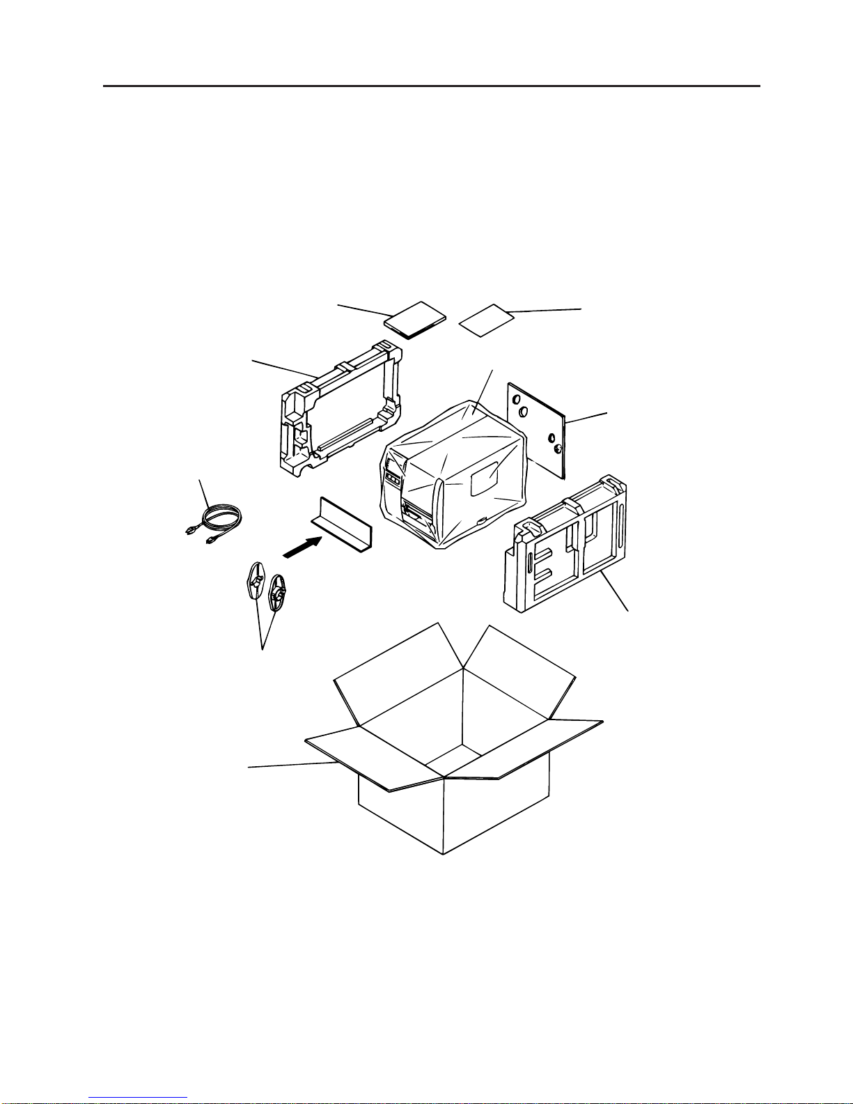
1. UNPACKING
1.1 Procedure
1) Open the carton.
2) Unpack the accessories from the carton.
3) Unpack the side pad (L)/(R) and the printer from the carton.
4) Place the printer on the level surface.
Owner's Manual
1.2 Checks
1) Check for damages or scratches on the machine.
2) Confirm that none of the accessories are missing.
NOTE: Keep the carton and side pads for later transport.
Side Pad (L)
Power Cord
Supply Holder
Carton
Side Pad (R)
Rear Pad
Thermal Printer
Unpacking Procedure
Fig. 1-1
2-1
2. MAJOR UNIT REPLACEMENT EM18-33011
(Revision Date: Dec. 09 '94)
2. MAJOR UNIT REPLACEMENT
2. MAJOR UNIT REPLACEMENT
CAUTION:
1.NEVERseparatetheribbonmotorsfromtheattachingplate,(bracket)because doing so will
change their adjustment. (See Fig. 2-8)
2.NEVER remove the two screws painted red on the side of the print block. (See Fig. 2-13)
3.NEVER remove the four screws on the side of the print block. (See Fig. 2-13)
4. NEVER remove the four screws painted red fixing the right plate and reinforcing plate. (See
Fig. 2-16) However, the machine with a serial number of 4Txxxxxx or later is not equipped
with the red screws because of the change in the right plate shape.
5.NEVER remove unmentioned screws because doing so will change their adjustment.
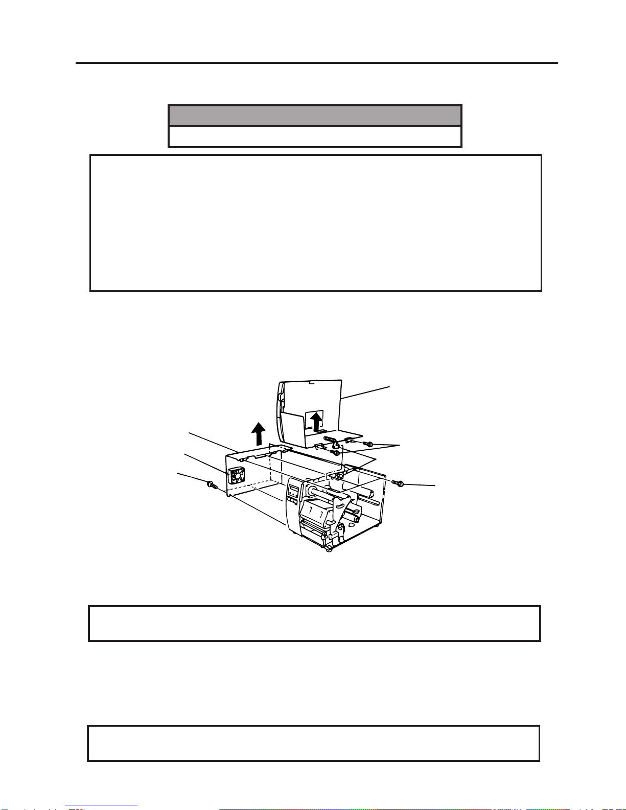
1) Turn the power off.
2) Open the top cover to remove the four FL-3x5 screws. Slide the top cover to the left to release the
damper and remove the top cover.
3) Remove the seven screws (FL-4x5 and B-4x5) to remove the left side cover.
4) Disconnect the FAN motor connector from the PS unit.
WARNING!
Disconnect the power cord before replacing the main parts.
Fig. 2-1
NOTE: Instructions to remove the top cover and left side cover are omitted from each removal/
installation procedure provided below.
■Lubrication
CAUTION: 1.Lubrication: During parts replacement
2.Kinds of oil: FLOIL G-488: 1kg kan (Part No. 19454906001)
Any machine is generally in its best condition when delivered; therefore, it is necessary to try to keep
this condition. Unexpected failure occurs due to lack of oil, debris or dust. To keep its best condition,
periodically clean the machine and apply proper kinds of oil to each part in which lubrication is needed.
Although the frequency of lubrication varies according to how much the machine is used, at least it is
necessary to lubricate before the machine becomes dry. It is also necessary to wipe off excessive oil
as it collects dirt.
CAUTION: Donotspraytheinsideoftheprinterwithlubricantsunsuitableoilcandamagethe
mechanism.
Top Cover
Screw (FL-3x5)
Screw (FL-4x5)
Left Side Cover
FAN Motor
Screw (B-4x5) Damper

2-2
2. MAJOR UNIT REPLACEMENT EM18-33011
(Revision Date: Oct. 14 '94)
2.1 Replacing the PS Unit, I/F PC Board and CPU PC Board
2.1 Replacing the PS Unit, I/F PC Board and CPU PC Board
CAUTION: Replace only with same type and ratings of fuse for continued protection against
risk of fire.
1) Remove the three FL-4x6 screws and disconnect the two connectors to detach the PS unit.
2) Remove the FL-3x5 screw and the four locking supports to remove the I/F PC board.
3) Disconnect the 9 connectors from the CPU PC board.
4) Remove the six screws (SM-3x6B, SM-3x6C) to detach the CPU PC board from the printer.
5) Replace the PS unit, I/F PC board and CPU PC board. Insert the connectors correctly and install in
the reverse order of removal above. Do not mount the left side cover and top cover.
6) Make sure to adjust the various voltages after replacing the CPU PC board.
Fig. 2-2
Fig. 2-3
Locking Support
Connector
Screw (FL-4x6)
PS Unit
Screw (FL-4x6)
Screw (FL-3x5)
I/F PC Board
Screw (SM-3x6B)
CPU PC Board
Screw (SM-3x6B)
Connector
Connector
Connector
Screw (SM-3x6B)
Screw (SM-3x6C)
Connector
Screw (SM-3x6B)
Connector

2-3
2. MAJOR UNIT REPLACEMENT EM18-33011
7) Adjust the ribbon end sensor.
Use the following Ribbons; TTM-78 (Maker:
Fujicopian)
(1) Set the ribbon so that the ribbon end sensor
can detect the ribbon. Turn the power on.
(2) TurntheVR1so thatthe voltagebetween Pin
1 (GND) and Pin 7of CN12 is 3.0 –0.2V with
an oscilloscope.
(3) Turn the power off and mount the left side
cover and top cover.
(Revision Date: Feb. 10, 2000)
2.1 Replacing the PS Unit, I/F PC Board and CPU PC Board
8) Adjust the black mark sensor.
As the black mark sensor is adjusted by key entries in system mode, refer to page 6-38 for the
adjustment procedure.
9) Adjust the feed gap sensor.
Asthefeedgapsensorisadjustedbykeyentriesinsystemmode,refertopage6-39fortheadjustment
procedure.
CAUTION: Be careful when replacing the CPU PC board, since a non-resettable counter
(IC13) is installed on this board. (Refer to Section 6.2.1 Maintenance Counter
Printing.)
If this counter should be reset, replace IC13.
Fig. 2-4
Fig. 2-5
VR1
GND
Voltage
3.0 –0.2 V
Range: 1 V / 0.2 m sec.
2-4
2. MAJOR UNIT REPLACEMENT EM18-33011
(Revision Date: Apr. 05 '94)
2.1 Replacing the Stepping Motor
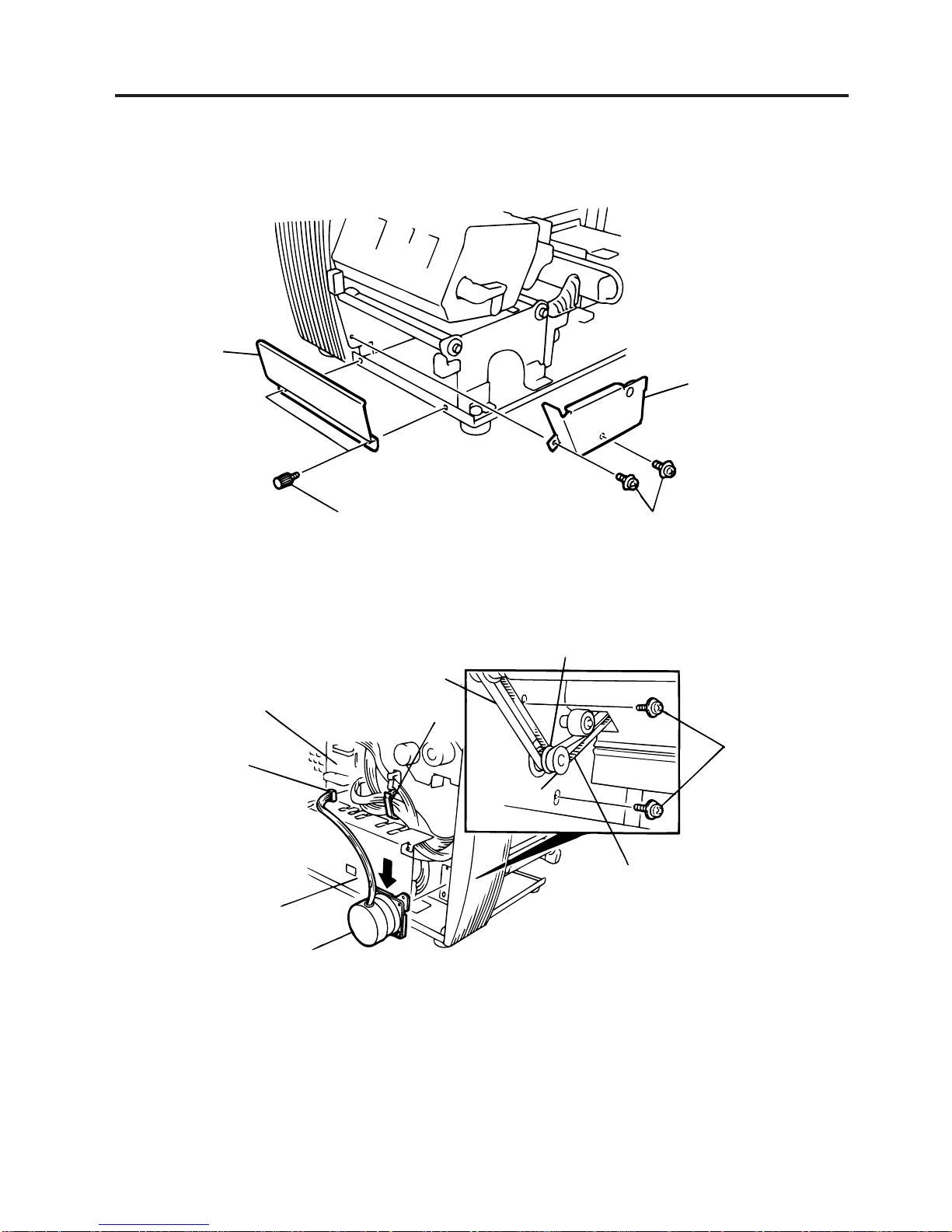
2.2 Replacing the Stepping Motor
1) Remove the two black screws to detach the front plate, remove the two FL-4x6 screws to detach the
belt cover.
Fig. 2-6
2) Unclamp and disconnect the connector from CN13 on the CPU PC board.
3) Remove the two SM-4x10C screws, loosen the two belts from the pinion gear, and remove the
stepping motor.
4) Whenreplacingthesteppingmotor,placetheplatenbeltfirstthenthefeedrollerbeltaroundthepinion
gear so that the partition is positioned between two belts. Hold down the stepping motor at 3.5 kg ±
300 g force and secure it so that the belts have no slack or disengagement.
5) Reassemble in the reverse order of removal.
Fig. 2-7
Belt Cover
Screw (FL-4x6)
Black Screw
Front Plate
Screw (SM-4x10C)
Feed Roller Belt
Partition
Platen Belt
Clamp
CPU PC Board
CN13
Pinion Gear
Stepping Motor
PS Unit

2-5
2. MAJOR UNIT REPLACEMENT EM18-33011
(Revision Date: Apr. 05 '94)
2.3 Replacing the Ribbon Motors
2.3 Replacing the Ribbon Motors
CAUTION: NEVERseparatetheribbonmotorsfromtheattachingplatebecausedoingsowill
change their adjustment.
1) Disconnect the connector and remove the two SM-3x5B screws to detach the ribbon motors.
Fig. 2-8
2) Replace the ribbon motors, then align the dowels to attach the ribbon motors. Reassemble in the
reverse order of removal.
2.4 Replacing the Take-up Motor
CAUTION: NEVERseparatethetake-upmotorfromthebracketbecausedoingsowillchange
the adjustment.
NOTE: The following procedure can be employed without removing the top cover and left side cover.
1) Remove the four FL-3x5 screws to detach the motor cover.
2) Remove the connector for the rewind full sensor (LED).
3) Disconnect the connector from the CN1 on the PWM PC board and remove the two FL-3x5 screws
to detach the take-up motor.
Fig. 2-9
4) Replace the take-up motor, then align the dowels to attach the motor cover and rewind full sensor
(Tr).
Dowels
Attaching Plate
FLOIL G-488
FLOIL G-488
Attaching Plate
Ribbon Motor
Screw (SM-3x5B)
Connector (Red)
Connector (Black)
Screw (SM-3x5B)
Connector (CN1)
Screw (FL-3x5)
Screw (FL-3x5)
PWM PC Board
Bracket
Take-up Motor
Connector
Ribbon Motor
Motor Cover

2-6
2. MAJOR UNIT REPLACEMENT EM18-33011
(Revision Date: Apr. 05 '94)
2.5 Replacing the Solenoid
2.5 Replacing the Solenoid
NOTE: The following procedure can be employed without removing the top cover and left side cover.
1) Before removing the ribbon stopper, check its attaching direction for later installation. Remove the
ribbon stopper from the ribbon shaft on which the ribbon is wound.
2) RemovethetwoSM-4x8Bscrews,disconnecttheconnectorCN1ontheRSVPCboardtodetachthe
solenoid unit.
Fig. 2-10
3) RemovethetwoSM-3x5BscrewsanddisconnecttheconnectorCN2ontheRSVPCboardtodetach
the solenoid.
Fig. 2-11
Connector CN1 (3 pin) Solenoid Attaching Plate Screw (SM-4x8B)
Ribbon Stopper
Ribbon Shaft
CN2 (2 pin)
RSV PC Board
Print Block
Connector CN2 (2 pin)
RSV PC Board
Solenoid
Solenoid Attaching Plate
Screw (SM-3x5B)
Table of contents
Other TEC Printer manuals

TEC
TEC B-680 Series User manual

TEC
TEC B-570-QQ SERIES User manual

TEC
TEC TEC EM1-33033 User manual

TEC
TEC TEC B-670 SERIES User manual

TEC
TEC B-370 Series User manual

TEC
TEC B-SX4T Series User manual

TEC
TEC B-450-QQ Series User manual

TEC
TEC CB-416 Series User manual

TEC
TEC tecjet 6090uv-xp600 User manual

TEC
TEC B-450 SERIES User manual

TEC
TEC B-880 series User manual

TEC
TEC TEC B-210 SERIES User manual

TEC
TEC CB-416-T3-QQ User manual

TEC
TEC TEC B-670 SERIES User manual

TEC
TEC TEC B-870 SERIES User manual

TEC
TEC TEC EO1-13016 User manual

TEC
TEC B-570-QP Series User manual

TEC
TEC B-480 SERIES User manual

TEC
TEC B-570 SERIES User manual

TEC
TEC B-672 Series User manual


