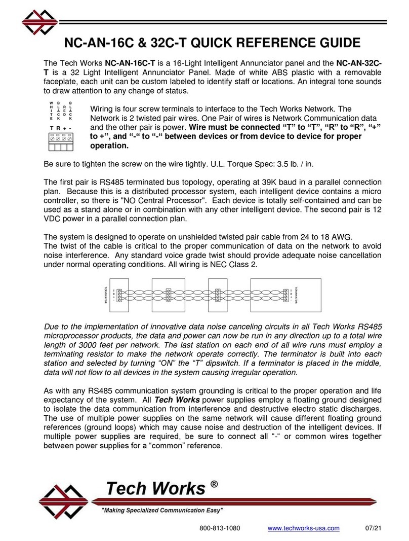
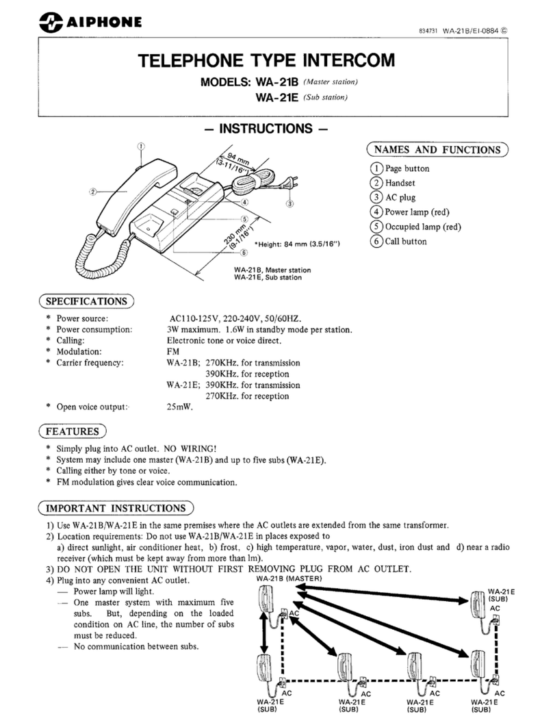
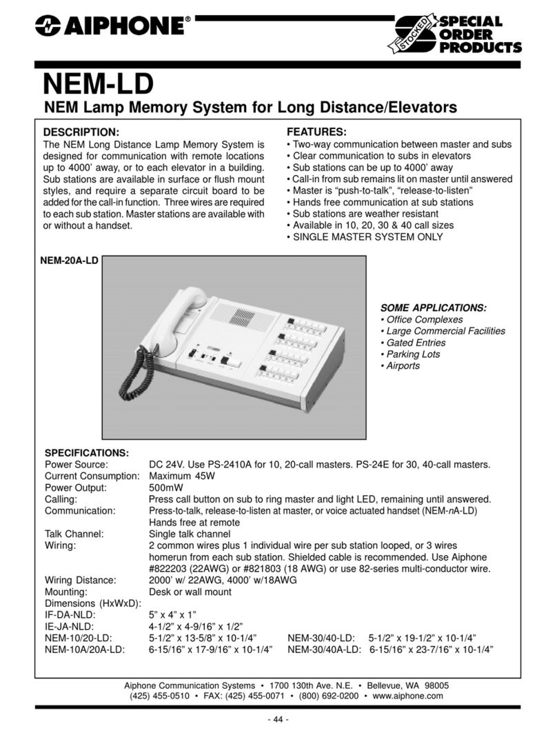
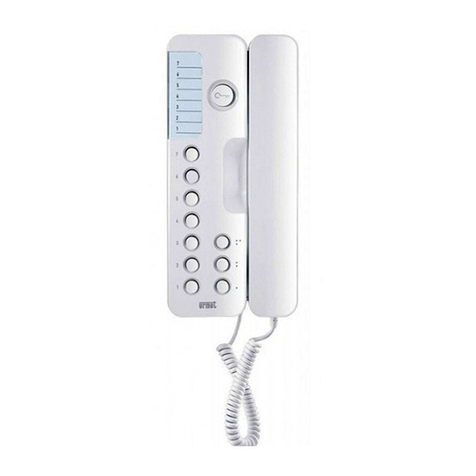
Tech Works CI-HSI-41 Technical manual

Tech Works, Inc., 7430 Eastgate Road, Suite 130, Henderson, NV 89011
Direct Line: 702-846-1080 Toll Free: 1-800-813-1080
Web site www.tech4people.com 6/17
The Tech Works CI-HSI-41 Headset Combiner
is part of the Collaborative Intercom product
group designed to take standard Plantronics
headsets and let them talk to each other as well
as other Tech works CI-Buss products. The CI-
HSI-41 accommodates up to four Plantronics
CS-540 lightweight, Wireless Headsets. The
headsets communicate with each other, as a
single headset with four summed microphones.
The Intercom can simply plug together using
standard CAT-6 patch cables. When connected
to another unit all headsets become part of that
system. Two CI-HSI-41 can be connected
together to make a single system of up to 8
headsets. The eight headsets act as one unit.
Initial setup is accomplished with built in level
indicator lights and the controls on the
receiver/charging base. Once completed, no
further adjustments should be required.
The CI-HSI-41 can be used as a small stand-
alone Wireless Headset Intercom or as an
addition to systems using microphones,
speakers, and other CI-Buss and PA-Buss
devices. By adding a PA-402 the headset
conversation can be played over ceiling
speakers so observers can hear the
conversation.
When combined with our full duplex, hands-free
intercom and other products the CI-HSI-41
provides a level of flexibility and control
unmatched in communication.
CI-HSI-41
Collaborative Intercom
Headset Combiner
System Planning &
Installation Manual
Associated Equipment
PA-402 Program and Paging Amplifier
CI-ODC-1 Collaborative Intercom
Operator Desk Console
CI-MSI-22 Collaborative Intercom
Microphone Speaker Interface
Design Information
Color: Light Gray metal enclosure
Power: 24VDC, 1A Power Supply (Not
included)
Weight: 2 lbs.
Dimensions: 8.5” W X 6” D X 1.75” H
Architects' and Engineers' Specifications
A 4 headset wireless communication system must be
provided for this project to have hands-free
communication without the use of fixed location
microphones and speakers or hardwired headset
connections. The Headset Combiner must be capable of
connecting at least 4 industry standard telephone
headsets and expandable to 8 headsets. The system must
include Automatic Level Control and the Collaboration
Intercom interface for connection to other Tech Works
CI-BUSS devices for a complete and operable system.
System connections must be via industry standard CAT-6
patch cords. The Headset Combiner shall operate from a
separate UL Listed 24 VDC 1 Amp power source.
The Collaborative Intercom Headset Combiner shall be
Tech Works Model CI-HSI-41
BENEFITS
Superior Sound Quality
Low Cost
Total Flexibility
Easy Set Up
Simple integration

6/29/2017 Tech Works CI-HSI-41 Systems Planning & Installation Manual Page 2 of 13
Table of Contents
Page
Front Controls and Indicators 3
Rear Connections 4
Initial Adjustments 5
Configuration Options 7
Headset Intercom Audio Pathways 8
PA-BUSS, Monitor/Communications, Output 9
CI-BUSS, Collaboration Buss 10
CI-HSI-41, Configuration Worksheet 11
Packaging & Mechanical 12
Accessories 13
Figures
Front Panel 3
Rear Panel 4
Simplified Connections 5
Simplified Block Diagram 6
Jumper Options 7
Headset Intercom Audio Pathways 8
Microphone Summing and ALC 8
PA-BUSS, Monitor Output Block diagram 9
CI-BUSS, Collaborative Buss Block Diagram 10

6/29/2017 Tech Works CI-HSI-41 Systems Planning & Installation Manual Page 3 of 13
The CI-HSI-41 is a stand-alone Headset Intercom that accommodates up to four Plantronics
Wireless Headsets. Another CI-HSI-41, may be connected to accommodate more Headsets.
The CI-HSI-41 is also a Collaboration Intercom Building Block, with three Functional
Modules:
Four Headsets
The PA-BUSS Monitor/Communications
CI-BUSS Interface
The “Configuration” ties the Functional Modules together with Jumpers.
The “Configuration” also determines how the CI-HSI-41 responds to external Audio, and Control
Inputs. Different “Configurations” support many applications.
Front Controls and Indicators:
MICROPHONES
COLLABO RATIVE INTERCOM
HEADSET INTERFACE
POWER
CI-HSI-41
LEVEL
PA / MONITOR
THRES -
HOLDGAIN 4321
HEADSETS ACTIVE
OP MIC
ACTIVE ON
Power indicator: Green when Operating Normally
CI-BUSS ALERT, Active Indicator: Green when the CI-BUSS is ALERTed.
Microphone Sensitivity:
16 Position Rotary Switch, factory set to “9
3dB/Step, 45dB Range
Talk Level Indicator:
Off; BUSSes are not receiving the Headset Microphone outputs
Green; low input level
Green flashing to Red, Normal Operation when ALC is active and the Headset Users are
talking.
Headset On indicators (4): Green when the Headset is connected, and turned on.
Monitor Level Knob Pot: Controls output level to PA-BUSS connector.
PA Monitor Indicator: Green when the BUSS has the Audio Output Enabled.

6/29/2017 Tech Works CI-HSI-41 Systems Planning & Installation Manual Page 4 of 13
Rear Connections:
24VDC - 550mA
CI-HSI-41
Tech Works * YORBA LINDA * CA * 1- 800-813 -1080 * WWW. T E CH4PEO PLE.COM
CALL-SW (-)
TALK-SW
COMMON
CALL-SW (+)
CI-BUSS
SLAVE
INPUT
PA- BUSS
MONITOR
OUTPUT
CI-BUSS
MASTER
OUTPUT
HEAD
SET
#4
HEAD
SET
#3
HEAD
SET
#1
HEAD
SET
#2
Headset (Four) Connectors: RJ-22, Telephone handset connectors
Talk Switch:
Two Position Euro-Style Barrier Strip:
Switch Common
Talk Switch (+) (N.O.)
CI-BUSS, “Master” Connector,RJ-45
CI-BUSS, “Slave” Connector,RJ-45
PA-BUSS, Monitor Output Connector, RJ-45, Always Powered
Maximum available PA-BUSS Power is: 23 Volts@ 350MA
Call Switch:
Two Position Euro-Style Barrier Strip:
Call Switch (+), (N.O.)
Call Switch (-)
Call Switch must Float W.R.T. Common
Power Connectors: (Two)
3.5mm Barrel Connectors
24Volts, 1.5 Amps Maximum, depending on Speaker load
Chassis, Earth Ground
Hex Nut
The Chassis is connected to Circuit Common through a 1-Meg-Ohm resistor

6/29/2017 Tech Works CI-HSI-41 Systems Planning & Installation Manual Page 5 of 13
Initial Adjustments:
To assure consistent performance each CS-540 requires initial adjustments.
Default Settings are:
Configuration Switch: “A”
Earphone Switch: “4”
Microphone Switch: “6”
CI-HSI-41 Microphone Gain Control: Set to “9”
Microphone setup should be confirmed, when speaking at a normal level.
While talking into a headset, the Talk Level Indicator on the CI-HSI-41, should flash red.
Turn the Microphone level switch on the bottom of each unit up or down until the CI-HSI-41 Talk
Level Indicator flashes Red.
After all the microphones are set up, the Listening Levels may be adjusted by the user by
adjusting the listening level on the headset itself.
The ”PA-OUPUT” Control sets the PA-BUSS output level.
Fully clock-wise is ~ 0dBM nominal output
There are several strategies for using this level setting:
1. Advance the control fully CW, and use the Amplifier Level Control for setting Speaker
Levels.
2. Set the Amplifier Level Control Fully CW, and use the HSI-41 Level Control to set
Speaker Levels.
3. If a system has several Amplifiers, the “Level” controls on the amplifiers may be used
for ‘Balance’; the level control on the HSI-41 may be used as a ‘Master Level’ control.
Note:
Before making any adjustments assure there is an Audio Output from the headset
receiver to the CI-HSI-41.
All the associated indicators must be lighted green.
24VDC - 550mA
CI-HSI-41
Tech Works * YORBA LINDA * CA * 1-800-813-1080 * WWW.TECH4PEOPLE.COM
CALL-SW (-)
TALK-SW
COMMON
CALL-SW (+)
CI-BUSS
SLAVE
INPUT
PA-BUSS
MONITOR
OUTPUT
CI-BUSS
MASTER
OUTPUT
HEAD
SET
#4
HEAD
SET
#3
HEAD
SET
#1
HEAD
SET
#2
PXX2410A
POWER SUPPLY
CS-540 Wireless Headsets (sold separately)
(sold separately)

6/29/2017 Tech Works CI-HSI-41 Systems Planning & Installation Manual Page 6 of 13
Functional Block Diagram (Simplified):
OR
SUM
ALC (HEADSETS)
MASTER INPUT
SLAVE INPUT
“LISTEN
LEVEL”
ALWAYS
CI-BUSS ALERT
TALK SW
SELECT
MUX AMP
ALWAYS
AUDIO
ALERT
PA-BUSS
OUTPUT
TALK SW
ALWAYS
1
ALC (HEADSETS)
SUM
2,3,4
PRE-AMP SUM
MICROPHONE 4 EARPHONE 4
4
1,2,3
SL
MA
PRE-AMP SUM
MICROPHONE 3 EARPHONE 3
3
1,2,4
SL
MA
PRE-AMP SUM
MICROPHONE 2 EARPHONE 2
2
1,3,4
SL
MA
PRE-AMP SUM
MICROPHONE 1 EARPHONE 1
1
2,3,4
TALK SW
ALWAYS
MASTER INPUT
SLAVE INPUT
SL
MAMASTER INPUT
SLAVE INPUT
M
ICROPHONES ARE EXTERNAL
,
S
HOWN HERE FOR CLARITY
E
ARPHONES
ARE
EXTERNAL
,
S
HOWN HERE FOR CLARITY
SUMALC (HEADSETS)
PA-BUSS INPUT
MASTER INPUT
SUMALC (HEADSETS)
PA-BUSS INPUT
SLAVE INPUT
“MASTER” AUDIO OUTPUT
“SLAVE” AUDIO OUTPUT
CI-BUSS
FOUR
HEADSETS
ALC
M
IC
G
AIN
8
7
6
5
4
3
2
1
0
F
E
D
C
B
A
9
Simplified Block Diagram to illustrate the Configuration Jumper Options
Major Component not shown:
Transformers, Opto-Couplers, Audio Buffers

6/29/2017 Tech Works CI-HSI-41 Systems Planning & Installation Manual Page 7 of 13
Configuration Options:
The CI-HSI-41 is designed to accommodate many applications. For most applications the
factory default setting is sufficient. For ‘special’ applications a few jumpers may need to be
moved. These Jumpers determine how the CI-HSI-41 interacts with other Components of the
System.
Before attempting a Configuration you should review the "User Guide" CI & PA, BUSS
sections.
The "Standard Configuration" is a Four Headset Intercom that may be used with an Operator
Console.
The PA-OUT, is used as Monitor/Communications Output, including all Collaboration audio.
Jumper Options
The following is an explanation of the options, using the 'Standard Configuration" as an
example.
In some installations some of the headset users only listen in on the conversation. This is
accomplished by turning off the microphone at the Base Station See the Plantronics User’s
Manual.

6/29/2017 Tech Works CI-HSI-41 Systems Planning & Installation Manual Page 8 of 13
Headset Intercom Audio Pathways:
PRE-AMP SUM
MICROPHONE 4 EARPHONE 4
4
1,2,3
SL
MA
PRE-AMP SUM
MICROPHONE 3 EARPHONE 3
3
1,2,4
SL
MA
PRE-AMP SUM
MICROPHONE 2 EARPHONE 2
2
1,3,4
SL
MA
PRE-AMP SUM
MICROPHONE 1 EARPHONE 1
1
2,3,4
TALK SW
ALWAYS
MASTER INPUT
SLAVE INPUT
SL
MAMASTER INPUT
SLAVE INPUT
M
ICROPHONES ARE EXTERNAL
,
S
HOWN HERE FOR CLARITY
E
ARPHONES
ARE
EXTERNAL
,
S
HOWN HERE FOR CLARITY
FOUR
HEADSETS
Each Headset's microphone is summed to all the other Headsets Earphones except itself
this sum is known as “All others, except me”.
Headset # 1 may have its microphone controlled by the “Talk Switch” or be “Always On”, which is
a jumper selection inside the unit.
There are three Audio Pathways in the HSI-41:
Communications between Headsets
Communications on the Collaboration Buss, CI-BUSS
Monitoring Output to the PA-BUSS
All inputs are Summed before the ALC for a common group signal.
The ALC passes signals, when the Talk Switch is Active, TALK_SW or ALWAYS.
8
7
6
5
4
3
2
1
0
F
E
D
C
B
A
9
MICROPHONE GAIN
~3dB/STEP
ALC (HEADSETS )
~0dBm
AUTOMATIC LEVEL
CONTROL (ALC)
T
HRESHOLD OF
L
IMITING
I
NDICATOR
O
FF
= M
UTED
G
REEN
= O
N
R
ED
(F
LASHING
) =
L
IMITING
MUTE
TALK SW
ALWAYS
1
SUM
2,3,4
Headset #1 Microphone always sums to the BUSSes, the others are jumper selectable.
Headset #2 thru #4 Microphone sums ON OFF, jumper selectable.
The ALC may be enabled, or inactive (Muted). This has no effect on headset to headset
Communications.
Headset # 1 may Selectively Listen the CI-BUSSes:
Master Connector: ON OFF
Slave Connector: ON OFF
Headsets #2 thru #4 may Selectively Listen the CI-BUSSes:
Master Connector: ON OFF
Slave Connector: ON OFF

6/29/2017 Tech Works CI-HSI-41 Systems Planning & Installation Manual Page 9 of 13
PA-BUSS, Monitor/Communications, Output, has many uses:
OR
SUM
ALC (HEADSETS)
MASTER INPUT
SLAVE INPUT
“LISTEN
LEVEL”
ALWAYS
CI-BUSS ALERT
TALK SW
SELECT
MUX AMP
ALWAYS
AUDIO
ALERT
PA-BUSS
OUTPUT
It could be:
A logging output, for recording the conversation, or just selected individuals.
A “paging” output to talk to people observing a procedure.
Used for Patient Communications, to talk to the patient that is undergoing a procedure
such as an MRI.
There could be Background Music, which is only interrupted when communications or Paging
takes place. For the various applications see the PA-BUSS Section of the main Systems
Planning guide.
The PA-BUSS Monitor has several Audio Selection Choices, which are summed:
Master Connector: ON OFF
Slave Connector: ON OFF
Headsets: ON OFF
Each of these selections determines what is sent out of the PA-BUSS Output connector. This
could determine what comes out of a speaker, or what is heard by another device connected to
the PA-BUSS.
The Audio May be Keyed (See below) or may always be enabled KEYED ALWAYS
The PA-BUSS Monitor ALERT Signal (Keying Signal) is selectable, logical OR’ed
Talk Switch Active TALK_SW ON OFF
CI-BUSS is ALERTed CI-BUSS_ALERT ON OFF
Always (Overrides other selections) ALWAYS ON OFF
The Alert signal determines when other devices connected to the PA-BUSS Output reat to
commands from the PA Output. This would include muting of Music or turning on Paging.
The PA-BUSS is always powered, 23 Volts, at a Maximum of 300 Milliamps
This power is made available to run modules connected to the PA-BUSS.
For more details on the PA-BUSS please see the PA-BUSS Section of the main Systems
Planning guide.

6/29/2017 Tech Works CI-HSI-41 Systems Planning & Installation Manual Page 10 of 13
CI-BUSS, the Collaboration Buss, allows chaining of several Units:
OPTO
RCVR
BUFFER SUMALC (HEADSETS)
PA-BUSS INPUT
MASTER INPUT
CI-BUSS “SLAVE”
AUDIO OUTPUT
CI-BUSS “SLAVE”
AUDIO INPUT SLAVE INPUT
BUFFER SUMALC (HEADSETS)
PA-BUSS INPUT
SLAVE INPUT
CI-BUSS “MASTER”
AUDIO OUTPUT
CI-BUSS “MASTER”
INPUT AUDIO MASTER INPUT
CI-BUSS ALERT
CI-BUSS ALERT
CI-BUSS ACTIVE
CI-BUSS INTERFACE
In the Standard Configuration all the users of the CI-BUSS talk and listen to each other.
However there may be situations where some users may only listen, or only talk.
There are two Collaboration Buss connectors on the HSI-41. One is Labeled “Master” and the
other is labeled “Slave”. The Jumpers illustrated above determine what is sent out of the SLAVE
connector or the MASTER connector.
The Jumper Selections allow selective Collaboration or communication between units on the
chain. So just because something comes into the Slave Connector, does not mean that it has to
go out of the Master connector to the other devices. By moving the Jumpers the installer can
determine what comes in and what goes out of each connector independently. Changing one
selection does not affect another.
These settings do not affect the Monitor/Communications Output, PA-BUSS.
Slave IC-BUSS Connector, BUSS Output, Summed:
Master Connector: ON OFF
Headsets: ON OFF
Master IC-BUSS Connector, BUSS Output, Summed:
Slave Connector: ON OFF
Headsets: ON OFF
The Call Pair is a "Party Line" passing through to all the Blocks forming a Group.
The Operator Console Responds to a Switch Closure by initiating a Calling Sequence.
All Switches must be floating, or isolated with Opto-Couplers.
The Alert Pair is a "Party Line" passing through to all the Blocks forming a Group.
The Operator Console sends a signal to all the Other Blocks, such as my Microphone is On.
The other Blocks may be configured to "Respond" in an appropriate manner.
Responder Blocks, are electrically isolated, with Opto-couplers.
For more details on the CI-BUSS please see the CI-BUSS Section of the main Systems Planning
guide.

6/29/2017 Tech Works CI-HSI-41 Systems Planning & Installation Manual Page 11 of 13
CI-HSI-41, Configuration Worksheet:
"Standard Configuration" shown in Red
Headset Microphones:
Some headsets may be setup as only ‘listeners’
Microphones are shut off at the Base Station
Microphone 1
ON OFF
Microphone 2
ON OFF
Microphone 3
ON OFF
Microphone 4
ON OFF
Headset BUSS AUDIO Sources:
Summed
Headset #1, Microphone is always Summed
Headsets #2 thru #4, Microphones
ON OFF
Headsets Microphone AUDIO:
After ALC, Summed Audio
Always Active, ALWAYS
Only when the Talk Switch is Active, TK-SW
Headset #1, Microphone Enabled:
ALWAYS
Only when the Talk Switch is Active, TK-SW
Headset #1, Listens to the CI
-
BUSSes:
Master Connector, ON OFF
Slave Connector, ON OFF
Headsets #2 thru #4, Listens to the CI
-
BUSSes:
Master Connector, ON OFF
Slave Connector, ON OFF
PA
-
BUSS Output Connector:
Monitor/Communications
Signal Sources:
Summed to Output
Audio Pair (Pins 4&5) carry Summed audio
Master IC-BUSS Connector, Could be more Headsets, etc
ON OFF
Slave IC-BUSS Connector, Could be Operator Microphone
ON OFF
Headset, After ALC, All the Headset Microphones summed
ON OFF
Keyed/ALERTed when:
Logically OR’ed to Output (Pins 7&8)
The CI-BUSS is ALERTed
ON OFF
Talk Switch is Active
ON OFF
Always, other Jumpers Ignored
ON OFF
Audio Output is present:
ALWAYS
When KEYED
Slave IC
-
BUSS Connector:
Could
be Operator
Master IC-BUSS Connector, Could be more Headsets, etc
ON OFF
Headset, After ALC, All the Headset Microphones summed
ON OFF
Master IC
-
BUSS Connector:
Could be another HSI
-
41
Slave IC-BUSS Connector, Could be Operator Microphone
ON OFF
Headset, After ALC, All the Headset Microphones summed
ON OFF
All Headsets have their Microphone enabled at the their
respective base Stations
Headset 1 Microphone on the BUSSes
Headset Microphone Audio is Always available to the
BUSSes
Headsed1, Microphone always Enabled
Headset 1, listens to the Collaboration BUSSes
Headsets 2 thru 4 listen to the Collaboration BUSSes
The PA-Buss Monitor Output includes all
Audio Signal Sources
The PA-BUSS Output is always On
The Monitor Audio is keyed
However, it is always present (See Above)
All Audio Source are sent to the
Slave CI-BUSS Connector
All Audio Source are sent to the
Master CI-BUSS Connector

6/29/2017 Tech Works CI-HSI-41 Systems Planning & Installation Manual Page 12 of 13
Packaging & Mechanical:
1U, Half Rack, 8.60” X 1.75” X 6.00”
Mounting Options: Table-Top; Under Counter; Rack
Modular aluminum and steel enclosure
LEFT SIDE FRONT RIGHT SIDE
RACK MOUNT
RM-1

6/29/2017 Tech Works CI-HSI-41 Systems Planning & Installation Manual Page 13 of 13
Accessories
CS-540 WIRELESS HEADSET - When the user requires mobility, privacy, and
quality the CS-540 does it all in a light weight rechargeable package with an
integral over the ear mounting band.
PRO 45 HANGING MICROPHONE - In the procedure room area such as an
operating table the PRO 45 is a high quality condenser microphone with cardioid
pattern for excellent signal to noise and 25’ cable included for easy connection.
PRO 47T -PLUS - MICROPHONE with a DESK STAND BASE and Two
Switches. This is the perfect solution for the Cath Lab operator location. It is an
attractive professional assembly complete with a Blue “Talk” and an Amber
“Listen” switch to allow complete control of communication flow.
PRO42
-
is a wide-range miniature condenser microphone with a hemi-cardioid
polar pattern. It was designed for surface-mounted applications in high-quality
sound reinforcement and other demanding sound pickup situations like procedure
room boom arms.
HM
-
1
-
Hidden Microphone
-
The HM-1 is an Omni-Directional Condenser
Microphone with an electronically balanced preamp designed for interview pick
up. This is a complete assembly including a 1-gang face plate and mounting
hardware.
FS
-
1
-
ODC
–
Foot Switch for the Operator Desk Console
allows the operator
to use the microphone as a Push-To-Talk unit without tying up their hands to use
a button.
FS-1-PLUS - CALL / CONTROL SWITCHES - The FS-1-PLUS which includes
a 15 foot cable with connectors and wall plate. Both offer a variety of hands free
call in and control options.
System 21 - is a complete cost, effective, assembly that includes a high-quality
8" loudspeaker, 25V transformer and perforated steel grill. This unit is made to
“Blind Mount” in to hard ceilings.
System 5 CEILING MOUNT SPEAKER System- This is a complete assembly
including a back box and mounting hardware. The System 5 comes complete
with a 25 volt transformer or is available as the System 5-8 in 8 Ohm for Music
playback.
WM WALL OR UNDER COUNTER MOUNT – All Tech Works Universal Box
products are available with 1” metal tabs on each side of the unit for easy
attachment to either a wall or the underside of a counter. Also available in a side
by side WM2 .
RM RACK MOUNT - All Tech Works Universal Box products can be rack
mounted as either a single unit, dual units (side by side), or as companions with
accessories like the PA-402 Amplifier. The rack mount is 1 rack unit (1-7/8”) High
by EIA 19” Wide.
CAT6
-
* Computer Patch
Cables
,
for plugging CI and PA Buss modules together
to make a system. Available in a variety of lengths from 1 foot to 50 feet.
PC
-
* Power Cords,
for sharing system power between CI and PA Buss modules
together to make a system. Available in a variety of lengths from 1 foot to 50 feet.
PAGE
ACTIVE
PROGRAM AND
PAGING AMPLIFIER
POWER
PA-402
LEVEL ACTIVELEVEL
PROGRAM
PAGE
ACTIVE
PROGRAM AND
PAGING AMPLIFIER
POWER
PA-402
LEVEL ACTIVELEVEL
PROGRAM
Table of contents
Other Tech Works Intercom System manuals
