Tech Works CI Series Technical manual

Tech Works, Inc., 7430 Eastgate Road, Suite 130, Henderson, NV 89011
Direct Line: 702-846-1080 Toll Free: 1-800-813-1080
Web site www.tech4people.com 10/19
The CI Series is the most full-featured, flexible
communications system available anywhere,
at any price. Designed for the most demanding
environments, CI Series systems can be
custom configured to fit any space. Easy to
install, easy to configure, easy to integrate, the
CI SERIES’ modular design makes system
design a breeze. The modular design enables
you to custom configure the best system for the
job. Select components you need, locate them
where they need to be, and put them together
via fast, dependable CAT6 connectivity.
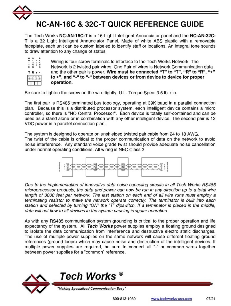
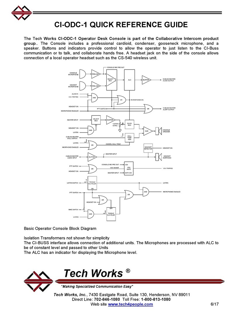
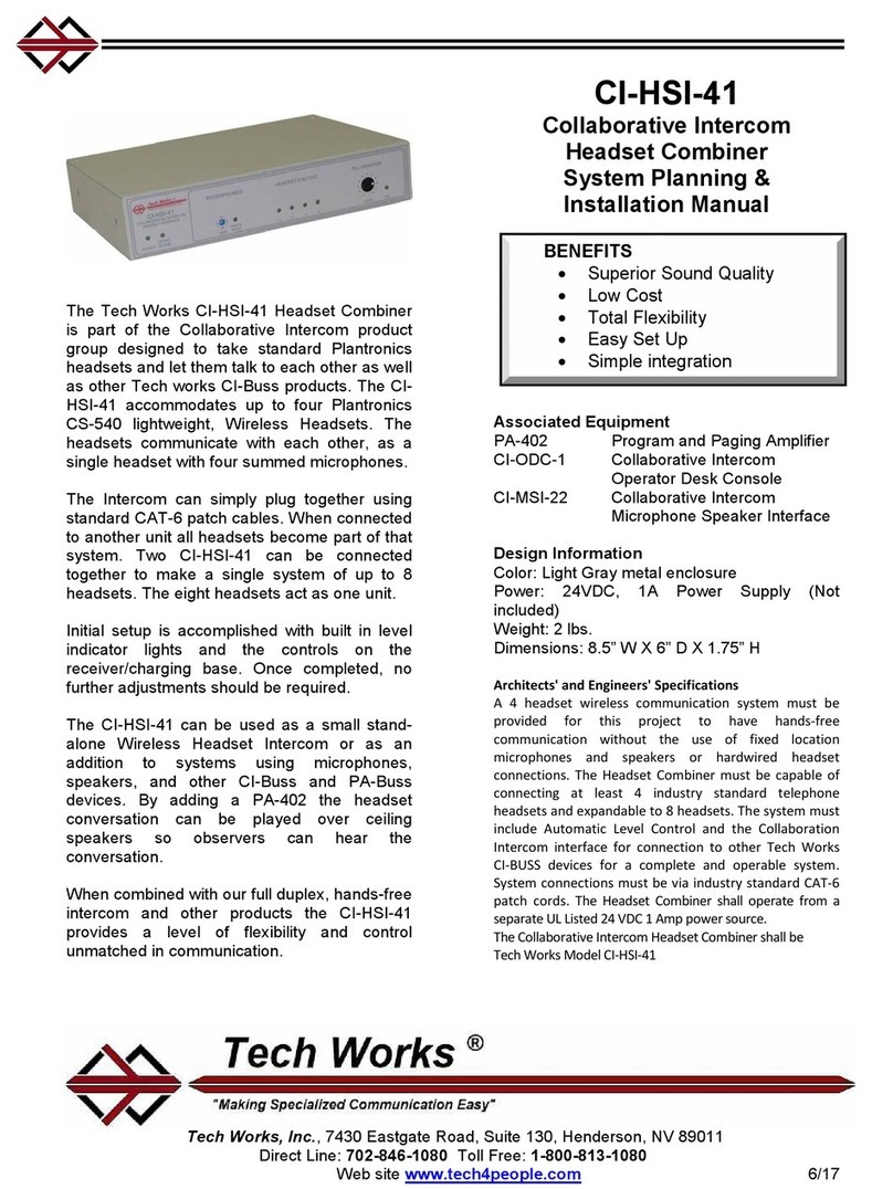
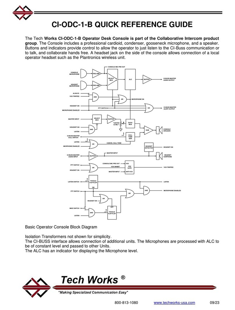
The Tech Works CI-Series Collaborative
Intercom system includes Microphones,
Speakers, the CI-MSI-22 Microphone Speaker
Interface control unit, Wireless Headsets, the
CI-HSI-41 Headset Interface unit, the CI-ODC-
1 Operator Desk Console, and many more
accessories like foot operated switches.
The system is based on a sophisticated
Automatic Level Control technology which
delivers consistent, crystal clear, intelligible
sound, from a whisper to a shout. With easy
integration to third party headsets,
microphones, and speakers, there is almost no
limit to how you configure your system;
CI Series
Collaborative Intercom System
System Planning Guide
Associated Equipment
CI-HSI-41
Headset Interface
CI-MSI-22
Microphone / Speaker
Interface
CI-ODC-1
Operator Desk
Console
CI-ODC-4
4 Group Operator
Desk Console
PS-2437A
24VDC Power Supply
Design Information
Power
24V DC
Wiring
CAT6 Patch Cables
BENEFITS
•Fully Configurable
•Full Duplex, Hands-free Audio
•Universal Microphone Inputs
•Built In Phantom Power
•Built In Equalization
•Automatic Level Control
•Background Music Ducking
•25 Volt Audio Power Amplifiers
•Vox or Push To Talk Operation
•Broadcast Quality Balanced
Line In/Out for
Interface to Teleconferencing

10/29/2019 Tech Works CI-Series Systems Planning & Installation Manual Page 2of 42
How to use this Manual
Those wishing to use one of the standard Configuration Templates should first read the Overview,
and then proceed to the appropriate Configuration Template for your application. The Setup,
Adjustments section should also be read before installation.
For those users who wish to do their own engineering, all sections may be useful. You may also
wish to contact a Tech Works application engineer for assistance, feel free, we’re here for you.
Table of Contents
Page
CI-BUSS Components 4
Basic System Overview 10
CI-BUSS Connection 11
PA-BUSS Connection 13
Selective Monitoring 14
Ducking 15
Automatic Level Control, ALC 17
Audio System Setup 18
CI-HSI-41 –Headset Interface 5 &20
CI-MSI-22 –Microphone Speaker Interface 5 & 24
CI-ODC-1 –Operator Desk Console 4 & 29
CI-ODC-4 –Operator Desk Console 4 & 33
Typical System Wiring Diagram 36
Packaging and Mechanical 39
Best Practices & FAQs 40

10/29/2019 Tech Works CI-Series Systems Planning & Installation Manual Page 3of 42
Figures
CI-ODC-1 Operator Desk Console 4 & 29
CI-ODC-4 Operator Desk Console 4 & 33
CI-HSI-41 Headset Interface 5 & 20
CI-MSI-22 Microphone Speaker Interface 5 & 24
FS-ODC - Operator Foot Switch 6
FS-1-PLUS –Procedure Room Foot Switch 6
CS-520 - Dual-Muff, Noise Cancelling Headset 6
CS-540 - Convertible Headset 6
PRO-42 - Boundary Microphone 6
PRO-45 Hanging Microphone 6
MJ-1 - Microphone Jack 7
PRO-SGM - Shotgun Microphone Assembly 7
PRO-ODM - Operator Desk Microphone 7
HM-1 Omni-Directional Hidden Microphone 7
System 2 Wall Mount Speaker 7
System 21 Round Ceiling Mount Speaker 7
System 5 Ceiling Speaker 7
PA-402 Paging and Program Amplifier 8
PA-SI-1 Paging and Program Speaker Interface 8
PMI-B - Portable Music Interface 8
CAT6-BB - RJ-45 Cable Breakout Board 9
CAT6-* Patch Cord 9
PS-2437A - 24VDC @3.7A Power Supply 9
PC-* Power Patch Cable 9
CI-BUSS Connector 11
System Functional Block Diagram 12
PA-BUSS Connector 13
PA-BUSS Chain 13
Selective Gain Reduction, “Ducking” 15
Master Slave Connection Diagram 16 & 39
Automatic Level Control, ALC 17
Typical System Wiring Diagram 36-38
Packaging and Mechanical 39
CI-BUSS Crossover wiring 40

10/29/2019 Tech Works CI-Series Systems Planning & Installation Manual Page 4of 42
CI-BUSS Collaborative Intercom Components
CI-ODC-1 –Operator Desk Console
The Tech Works CI-ODC-1 Operator Desk Console includes a
professional cardioid, condenser, gooseneck microphone, and a
speaker. Buttons and indicators provide control to allow the operator to
just listen to the CI-Buss communication or to talk, and collaborate
hands free. A headset jack on the side of the console allows connection
of a local operator headset such as the CS-540 wireless unit.
Setup is plug and play with an integral speaker level control to adjust
the listening level. No further adjustments should be required for
standard operation. Integral VOX and ALC allow for full duplex
conversations without feedback.
Internal, installer settable, jumper options allow the functionality of the CI-ODC-1 to be Hands-
Free or Push-To-Talk. The Push-To-Talk button can be either latching (Push On, Push Off) or
momentary, meaning the microphone is active as long as the operator holds the button down.
The CI-ODC-1 is a CI-BUSS Master device designed to control other units or functional blocks in
a system. If there is a device in the system that has a “Call” input, like the CI-MSI-22, when a
contact closure on the Call input sends a Buss Call signal the CI-ODC-1 will emit a tone sequence
to let the Operator know that someone is trying to get their attention.
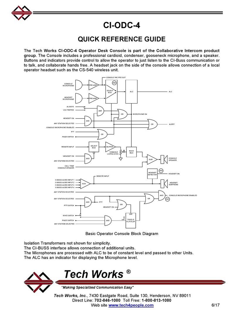
CI-ODC-4 –Operator Desk Console
The CI-ODC-4 allows a single operator location to communicate
selectively with up to 4 separate systems in 4 separate rooms. It includes
a professional cardioid, condenser, gooseneck microphone, and a
speaker. Buttons and indicators provide control to allow the operator to just
listen to the CI-Buss communication or to talk, and collaborate hands free.
A headset jack on the side of the console allows connection of a local
operator headset such as the CS-540 wireless unit.
Setup is plug and play with an integral speaker level control to adjust the
listening level. No further adjustments should be required for standard
operation. Integral VOX and ALC allow for full duplex conversations
without feedback.
The CI-ODC-4 can be used in a small Intercom when connected to a single CI-Buss product or
as an addition to larger systems using microphones, speakers. The CI-ODC-4 can also function
as an audio combiner to allow multiple rooms to collaborate.
Internal, installer settable, jumper options allow the functionality of the CI-ODC-4 to be Hands-
Free or Push-To-Talk. The Push-To-Talk button can be either latching (Push On, Push Off) or
momentary, meaning the microphone is active as long as the operator holds the button down.
The CI-ODC-4 is a CI-BUSS Master device designed to control other units or functional blocks in
a system. If there is a device in the system that has a “Call” input, like the CI-MSI-22, when a
contact closure on the Call input sends a buss Call signal the CI-ODC-4 will emit a tone sequence
to let the Operator know which room is trying to get their attention.

10/29/2019 Tech Works CI-Series Systems Planning & Installation Manual Page 5of 42
CI-HSI-41 –Headset Interface
The Tech Works CI-HSI-41 Headset Combiner isdesigned to take standard Plantronics headsets
and let them talk to each other as well as other Tech Works CI-Buss products. The CI-HSI-41
accommodates up to four Plantronics CS-540 lightweight, Wireless Headsets. The headsets
communicate with each other, as a single headset with four summed microphones.
The Intercom can simply plug together using standard CAT-6 patch cables. When connected to
another unit all headsets become part of that system. Two CI-HIS-41 can be connected together
to make a single system of up to 8 headsets. The eight headsets act as one unit.
Initial setup is accomplished with built in level indicator lights and the controls on the
receiver/charging base. Once completed, no further adjustments should be required.
The CI-HSI-41 can be used as a small stand-alone Wireless Headset Intercom or as an addition
to systems using microphones, speakers, and other CI-Buss and PA-Buss devices. By adding a
PA-402 the headset conversation can be played over ceiling speakers so observers can hear the
conversation.
CI-MSI-22 –Microphone Speaker Interface
The CI-MSI-22 consists of five Functional Modules; Two Inputs; The local Microphone/Line Input
and the PA-BUSS Input, Two Outputs; a 25 Volt Speaker Output and the PA-BUSS Output, and
the CI-BUSS Interface. The Jumper Options determine how these Modules interact and function
with each other. The "Standard Configuration" is a Remote (Single Location) for use with an
Operator Console. The Power Amplifier, is used for a Procedure Room Speaker while the
Microphone Input is used for a boom mounted or hanging Procedure Room Microphone. The PA-
OUT, is used as Procedure Room Monitor Output, perhaps for Background Music. The
PA-IN, may be used for an additional Microphone. The CI-BUSS, may be used with other
Interfaces, such as a CI-HSI-41 to include Headsets.
Initial setup is accomplished with built in level indicator lights and the controls. Once completed,
no further adjustments should be required. Integral ALC, Variable Notch Filters, and Speaker
Ducking allow for full duplex conversations without feedback.

10/29/2019 Tech Works CI-Series Systems Planning & Installation Manual Page 6of 42
FS-ODC - Operator Foot Switch
The FS-ODC is used in the control room for push-to-talk when hands are busy.
Our Foot Switches are ruggedly designed for harsh environments with a rubber
non-slip pad and 10-foot rubber jacketed cord. The FS-ODC is used in the
control room for push-to-talk when hands are busy.
FS-1-PLUS –Procedure Room Foot Switch
The FS-1-PLUS is used as a call button in the controlled environment to
summon an operator.
CS-520 - Dual-Muff, Noise Cancelling Headset
Mobility is key incontrolled environments and our headsets give professionals just
that. Using DECT technology, these headsets provide secure two-way
communications between the controlled environment and operators. Standard
controls on either headset operates features of the CI-Series system such as
listen, talk, mic mute, and level. The CS-520 is a wireless dual-muff noise
cancelling headset with an adjustable boom microphone.
CS-540 - Convertible Headset
The CS- 540 is a flexible, light weight, wireless, over-the-ear-
worn, convertible headset which offers you a choice of wearing
options.
PRO-42 - Boundary Microphone
There are several microphone options for different needs. The PRO-42 is a boundary
microphone which is a high quality and cost-effective solution mounting close to the
audio source.
PRO-45 Hanging Microphone
Our PRO-45 hanging cardioid microphone is a very high quality and easy to install
microphone; just watch out for hanging equipment.

10/29/2019 Tech Works CI-Series Systems Planning & Installation Manual Page 7of 42
MJ-1 - Microphone Jack
The MJ-1 Microphone wall jack assembly is made available to make installation of
the PRO-42 and PRO-45 microphones easier. It is a 3 pin XLR jack mounted on a
white plastic deco plate with a single gang trim ring. A 6-inch wire pigtail is soldered
to the XLR jack so that the filed technician can terminate the field wire without
providing a soldering iron.
PRO-SGM - Shotgun Microphone Assembly
The PRO-SGM is a shotgun microphone assembly which includes a wall
plate, jack, cord, and gimble mount, so it easily mounts to a wall or ceiling
and can be easily directed toward the audio source. A 6-inch wire pigtail is
soldered to the XLR jack so that the filed technician can terminate the field
wire without providing a soldering iron. Everything you need is included for
proper installation.
PRO-ODM - Operator Desk Microphone
Our PRO-ODM Operator desk microphone can be used in a remote location where
someone may not have a headset but still needs to contribute to the conversation.
HM-1 Omni-Directional Hidden Microphone
Our HM-1 omni-directional hidden microphonemounts to a simple wallplate and is very
effective for observation areas.
We’ve selected the best and most popular 25V speakers to pair with the products we build.
The System 2 is a wall mount speaker
The System 21 is a round ceiling mount speaker which includes a backbox and
all required mounting hardware.
The System 5 is a ceiling speaker which replacesa standard size
acoustic ceiling tile.

10/29/2019 Tech Works CI-Series Systems Planning & Installation Manual Page 8of 42
PA-402 - Paging/Program Amplifier
The PA-402 is a Professional Audio Power Amplifier designed with the System Integrator in mind.
It is specifically designed for Background Music, and Paging Applications and may be used with
other Tech Works products to augment a variety of system designs. The PA-402 has Program
Audio Inputs, Paging Audio Inputs, and Control signals that select which Audio inputs aredirected
to the Speaker. These inputs are transformer balanced allowing several PA-402's to be connected
in tandem, for large distributed systems. There is also an unbalanced Stereo Input for “Local”
Music insertion. The logic allows for a wide range of control requirements including; Enabling,
Muting, Program, or Page selection. The PA-402 comes ready to use for most applications, and
there are Application Templates for other common uses. The PA-402 is fully protected against
overloads. The unit automatically recovers when any overload is removed.
PA-SI-1 –Speaker Interface
The PA-SI-1 Speaker Interface is a 1-Watt Utility Audio Power Amplifier
designed with the System Integrator in mind. The input is transformer
balanced allowing several PA-SI-1's to be connected in tandem. Power
comes from the PA-BUSS, to simplify wiring. The PA-SI-1 is fully protected
against overloads. The unit automatically recovers when any overload is
removed. Modular Construction makes the PA-SI-1 ideal for integrated
designs. The unit is small; mounting is flexible, and easy, so it is ideal for space conscious
requirements. Mounting options include Snap Track or stud mounting. All signals are
connectorized for ease of installation.
PMI-B - Portable Music Interface
The PMI-B is a Portable Music Interface for Bluetooth to connect devices
such as cell phones to play music in the procedure room. The PMI is
designed to plug directly into to the PA-402.

10/29/2019 Tech Works CI-Series Systems Planning & Installation Manual Page 9of 42
CAT6-BB - RJ-45 Cable Breakout Board
The Tech Works CAT6-BB is a RJ-45 Cable Breakout Board designed to take
our Tech Works CAT6 cables and make each conductor accessible by a screw
terminal and/or assignable by jumpers. These units are designed for the
systems integrator and are typically used with our Collaborative Intercom
products to allow fast easy installation with custom music systems or
telemedicine conferencing equipment. A built in opto-isolator provides a
normally open contact closure for controlling music mute on products not
provided by Tech Works.
CAT6-* Patch Cord (“*” specify Length in feet; 1, 3, 10, 25, 50)
The Tech Works CAT6-* (“*” specify Length) is an EIA 568B standard
computer network Patch Cable designed to connect our Tech Works
Collaborative Intercom (CI-Buss) and PA-Buss products together.
These units are designed for the systems integrator to make
installation Plug and Play.
PS-2437A - 24VDC @3.7A Power Supply
The Tech Works PS-2437A is a regulated computer grade
power supply capable of providing 3.75 Amps of power at 24-
Volts DC to any of our products. A 6-foot removable power
cord with a North American standard Edison connector is
included along with a metal mounting bracket to allow the
unit to be screwed to the wall or under a counter.
PC-* Power Patch Cable (“*” specify Length in feet; 1, 3, 10, 25, 50)
The Tech Works PC-* (“*” specify Length) is a Power Patch Cable
designed to connect our Tech Works Collaborative Intercom (CI-
Buss) and PA-Buss products together. These units are designed for
the systems integrator to make installation Plug and Play. 18-gauge power cord is made with 5.5
mm barrel connectors on each end for connecting 24 VDC power from one unit to the next.

10/29/2019 Tech Works CI-Series Systems Planning & Installation Manual Page 10 of 42
CI-BUSS Collaborative Intercom
Basic System Overview
The Tech Works CI-Series Collaborative Intercom system was designed to allow many
standardized components such as professional microphones, speakers, and headsets to
Collaborate to create a unique audio communication environment to best suit the particular
application. The CI-Series is a modular, expandable solution which gives professionals
working in separate rooms and environments the ability to speak to each other, hands free
and seamlessly, as if they were in the same room. For professionals working in controlled
environments such as Operating Rooms, Cath Labs, or Clean Rooms - sterile, hands free
communication is not only essential, but can be critical. Typically, these environments are
noisy; full of equipment and hard, reverberant surfaces. The rooms become an acoustical
challenge, resulting in unclear and unintelligible communication. The CI-system is based on
a sophisticated Automatic Level Control technology which delivers consistent, crystal clear,
intelligible sound, from a whisper to a shout.
An operator station can selectively speak with up to 4-different rooms or controlled
environments. Inside the controlled environment, there are many speaker and microphone
options; from personal headsets to boom mics and ceiling speakers, the CI-Series has a
solution for each professional working in your facility. And no one person dictates how the
other communicates; customizable flexibility is what makes the CI-Series Collaborative
Intercom truly unique.
Tech Works products use two simple Buss structures that support Collaboration Intercoms (CI-
BUSS), and Paging Amplifier (PA-BUSS) Signal Distribution. The use of standard busses allows
Tech Works products to plug together.
Simple systems may require a single Box; more complex systems may require several boxes.
The Collaboration Intercom Buss, CI-BUSS; has bi-directional Audio pathways for
Communications, and Control. Expansion is easy; units daisy-chain together to formCollaborative
Groups.
The PA-BUSS supports one direction; Background Music, Paging, Announcement Loops,
selective Monitoring/Communications and many other features.
All signals are electrically isolated to perform in the harshest environments, using transformers,
Opto-isolators, and floating elements, to eliminate ground loops. Short Circuit Protection ensures
units recover from temporary faults. Standard Category-6 wiring and terminations are used for
ease of installation.
Audio Signals are low impedance, transformer balanced and "Line Level" to provide maximum
isolation from crosstalk, and noise.
Each Product is "configurable", the functional sections are connected with jumpers. Therefore,
products may be 'customized' for the application.
The wiring architecture is Master to Slave. So to connect to functional units together all you do is
plug the CI-Master of one unit to the CI-Slave of the next unit.

10/29/2019 Tech Works CI-Series Systems Planning & Installation Manual Page 11 of 42
The CI-BUSS (Collaboration Buss) is a wired network using CAT6 patch cords that have four
signal pairs for bi-directional communication:
“Call” (Control) Indicates a Station wants service
“Slave” (Audio) Communications
“Master” (Audio) Communications
“Alert” (Control) Indicates Action is requested
Typical CI-BUSS Chain:
The Collaborative Intercom is made up of a collection of functional active modules, each with its
own functional design.
The CI-ODC, Operator Desk Console is designed to meet the needs of the Operator.
The CI-MSI, Microphone Speaker Interface is designed to meet the needs of the procedure room
microphone and speakers.
The CI-HSI is designed to combine control and process a group of 4 headsets.
By connecting functional modules together, the audio from one can be routed to and shared with
other modules to make a custom system.
CI-Buss Active Unit CI-Buss Active Unit CI-Buss Active Unit CI-Buss Active Unit
MASTER SLAVE MASTER SLAVE MASTER SLAVEAUDIO AUDIO AUDIO
Functional module units are always connected CI-Master connector to CI-Slave connector
The signals do not just pass from one unit to another. Each unit has distinct Buss inputs, outputs,
and make up gain so that the Buss stays at a consistent audio level. Each unit has Buss option
jumpers to select what audio from “this” unit is passed to the next unit.
By arranging the order of the units in the chain and selecting what audio is passed along the
installer can determine what each unit “hears”. For instance, if a chain is CI-ODC to CI-MSI to CI-
HSI, the MSI jumpers determine if the Operator hears the HSI and if the HSI hears the Operator.
If you change the order to ODC to HSI to MSI then the HSI determines who hears each other. If
you add a PA-402 Paging and Music amplifier to the system you can plug it into either the MSI or
the HSI and get different content listening results as well as different Music Muting.

10/29/2019 Tech Works CI-Series Systems Planning & Installation Manual Page 12 of 42
CI-BUSS Chain
A CI-BUSS system is made up of a chain of functional blocks of products each designed to do a
special job or function.
SUM
SUM
SUM
INPUT OUTPUT
THIS BLOCK
“MASTER”
“SLAVE”
The Inputs and Outputs, are transformer
coupled; omitted here for clarity
The box marked "THIS BLOCK" defines the function of this Building Block. A "BLOCK"
represents a functional component which is a CI part # and may have an "INPUT", or an
"OUTPUT", or both.
The SUMers, shown below, are part of every Block, and support the CI SERIES Interface. Each
Summer Mixes the Buss Audio signals with the local Audio Signals and Routes them based on
the installer configuration.
SUM
SUM
SUM
INPUT OUTPUT
BLOCK
“1”
SUM
SUM
SUM
INPUT OUTPUT
BLOCK
“2”
SUM
SUM
SUM
INPUT OUTPUT
BLOCK
“3”
SUM
SUM
SUM
INPUT OUTPUT
BLOCK
“4”
0
1+2+3+4
0+1 0+1+2 0+1+2+3
4
3+42+3+4
0+2+3+4 0+1+3+4 0+1+2+4 0+1+2+3
The Buss structure allows "Blocks" to be "Added" to form a "Chain. A chain is formed by
plugging a Master output into a Slave input of another unit.
Most system requirements are satisfied with a single "Chain", Very large system may have
several "Chains", defined as Groups, Groups may be joined together by a Hub, such as the
CI-ODC-4
Jumpers inside of each unit or Block allow the installer to select what comes in from the BUSS
and what goes out to the Buss. Please see the individual Installation Guide for each product for
more information about jumper selections and settings of each electronic component.
Automatic Level Control and Limiting is used to achieve the standard Output signal levels to
keep the sound quality consistent throughout a system.
The Call Pair is a "Party Line" passing through to all the Blocks forming a Group
The Operator Console Responds to a Switch Closure by initiating a Calling Sequence
All Switches must be floating, or isolated with Opto-Couplers
The Alert Pair is a "Party Line" passing through to all the Blocks forming a Group
The Operator Console sends a signal to all the Other Blocks, such as my Microphone is On
The other Blocks may be configured to "Respond" in an appropriate manner
Responder Blocks, are electrically isolated, with Opto-couplers
A CI-BUSS system is made up of a chain of functional blocks of products each designed to do a
special job or function.

10/29/2019 Tech Works CI-Series Systems Planning & Installation Manual Page 13 of 42
The PA-BUSS (Audio Distribution Buss) has four signal pairs for one-way communication:
“Buss Power” (Option) Current Limited, 23-Volts
“Program” (Audio Option) Background Audio or Music
“Page/Communications” (Audio) Page/Monitor/Communications Audio
“Alert” (Control) Indicates Action is Requested
AMPLIFIER “INPUT” CONNECTOR AMPLIFIER “OUTPUT” CONNECTOR
PROGRAM_(-) (6)
AMPLIFIER_INPUT_(+) (4)
AMPLIFIER_INPUT_(-) (5)
(4) AMPLIFIER_OUPUT_(+)
(5) AMPLIFIER_OUTPUT_(-)
(6) PROGRAM_(-)
PA-BUSS, AMPLIFIER: Internal Signal Connections, to RJ-45 Connectors
Signal Pairing: (1,2) Power I/O; (3,6) Program/Music or Alert Status; (4,5) Audio; (7,8) Control
POWER_(-) (2) Power I/O Option (-)
POWER_(+) (1) Power I/O Option (+)
(3) PROGRAM_(+)
PROGRAM_(+) (3)
SOURCE_ACTIVE_(+) (7)
SOURCE_ACTIVE_(-) (8)
(7) SOURCE_ACTIVE_(+)
(8) SOURCE_ACTIVE_(-)
(1) POWER_(+)
(2) POWER_(-)
Power Pass-Thru Option (+)
Power Pass-Thru Option (+)
Typical PA-BUSS Chain:
POWER
AUDIO
CONTROL
“SOURCE” “AMPLIFIER” “AMPLIFIER”
AMPLIFIED
SPEAKER SPEAKER
AMPLIFIER
PA-BUSS
OUTPUT
POWER
The “Audio Monitoring” may be selectable, adding together the audio sources as desired.
A separate Audio pair, "Program" may contain External Music or Program material.
“Amplifiers” may respond to an “ALERT” logic signal, by muting Music, and outputting
Page/Communications, or other action.
An “Amplifier” is defined as any Unit having a PA-BUSS Input.
Each PA Buss has one "Source”, and a "Chain" of "Amplifiers".
The Source provides Line Level "Page/Communications" Audio, and Control Signal.
A Power Pair is provided for Amplified Speakers, or Microphone Pre-Amplifiers.
The Source and Amplifiers in the "Chain" may share a Power or Control Connection.
The Amplifier may supply power to the Source, or The Source may supply power to the Amplifier.
The supply of power is one or the other, or neither, not both (Jumper Options).
The Audio and Control signal paths are Galvanically Isolated using Transformers and
Opto-Couplers.
Sources and Amplifiers may be locally bonded to Earth by a metal stud on each chassis.

10/29/2019 Tech Works CI-Series Systems Planning & Installation Manual Page 14 of 42
Tech Works Products have “Line Level” Inputs and Outputs, 0dBm (.775 Volts, RMS).
The Maximum Output of a "Source" is 0dBm, with the “LEVEL” Control set at maximum
(Fully CW).
For Tech Works Amplifiers, a 0dBM input corresponds to a Maximum rated Output.
Therefore with all the “LEVEL” controls at Maximum the full rated output is achieved.
However this setting is never used; there should always be some attenuation in the system.
Normally if there are two level controls in tandem, only one is used to set the level, the other is
set to maximum (Fully Clockwise).
When an Amplified Speaker is used, the Source PA-BUSS output Level Control is used.
When the PA-BUSS is used with an Amplifier (PA-402), the Amplifier Level Control is used.
In special circumstances with multiple amplifiers, there may be a desire for a “Master” Level
Control, with the Individual Amplifier Controls used for Balancing the System.
The Alert Pair is a "Party Line" passing through to all the Units forming an Amplifier Chain.
The PA-BUSS Source is the "Initiator" of the Alert, other units may take appropriate action.
Responder Units are electrically isolated, with Opto-couplers.
The ALERT signal requests the Amplifier or Logging Device to take action.
For example, the amplifier switches from Background Music (Program), to
Paging/Communication.
Tech Works BUSS products are designed to be configured for the application; functional sections
are connected with jumpers.
The multitude of configuration possibilities allows a few products to be configured for a myriad of
application possibilities! This design is very flexible; each system is customized for the application!
If amplifiers are in a chain, configuration switches allow different amplifiers to respond as required.
Some Units may ignore the request.
Monitoring maybe selective:
The, Source, /PA-BUSS Output, is the Sum of the appropriate Signal Sources.
Jumper Options select the audio signals on each Block to be output.
For example, only the "Slave" input, usually the Operator Microphone, may be sent to the output,
which is normally the ceiling speaker in the procedure room.

10/29/2019 Tech Works CI-Series Systems Planning & Installation Manual Page 15 of 42
OR
(+)
(-)
ALERT
PAIR
LOGIC
KEYING
SOURCES
The “ALERT” is a selectable sum (OR) of several keying signals options
The Monitor Audio may always be present, or may be Keyed
Keyed Audio is useful for Simple Logging/Monitor Devices, Audio is only present when desired
The PA-BUSS, ALERT Signal may be configured to interrupt the “Music” when it’s appropriate
For example, when the Microphone is active, to avoid music bleeding into the microphone
Feedback Prevention:
DUCK
AMP
AMP
“LISTEN
LEVEL”
NONE
LOW
MED
MUTE
Selective Gain Reduction, “Ducking” is used to determine how much to turn down the sound.
Many intercommunications systems require full Duplex Operation. That is, several users may be listening
and talking at the same time. This introduces many acoustic feedback paths
When a user enables their microphone, the PA-BUSS, Monitor Speaker may have its output reduced
Thus lowering the around the loop feedback gain, and Reducing Feedback
Example: To appreciate the concept, consider the PA-BUSS Output of the MSI-22
OR
SUM
ALC (MIC)
PA-BUSS INPUT
MASTER INPUT
SLAVE INPUT “LISTEN
LEVEL”
DUCK
MUX
TALK SW
CI-BUSS ALERT
ALWAYS
CI-BUSS ALERT
TALK SW
PA-BUSS IN ALERT
SELECT
MUX AMP
ALWAYS
AUDIO
ALERT
PA-BUSS
OUTPUT
PA-BUSS INPUT AUDIO
This is even simplified; "Ducking", Feedback Suppression, also has configuration Jumpers!!!

10/29/2019 Tech Works CI-Series Systems Planning & Installation Manual Page 16 of 42
The Audio, and Alert Outputs are a function of what the user needs for the application.
No jumpers; No outputs!!!
Install all of the Audio Source Jumpers, and set the MUX to "Always" and you get everything, all
of the time.
Install the Master and Slave Audio Source Jumpers, set the MUX to Always, perhaps this is a
Ceiling Speaker for the "This Room" (Where the Local Microphones are located).
Install the MIC and PA-BUSS Audio Source Jumpers, set the MUX to Always, perhaps this is a
Ceiling Speaker for the "Operator".
Install the MIC Audio Source Jumper, Key the MUX with the TALK SWITCH, the Microphone
could be used for Logging or Paging.
The ALERT control signal indicates a Special Function is required.
For example, the PA-402 may respond by replacing Background Music with Communications.
Key the ALERT with the CI-BUSS and Talk Switch...the Music goes away if someone is talking!
There are hundreds of ways to configure the PA-OUTPUT Functional Section, one of five
Functional Sections of the MSI-22!!!
And, the MSI-22 may be connected to many other Configurable BUSS products!
Including another MSI-22!
Simple systems may require a single Box; more complex systems may require several boxes.
The Collaboration Intercom Buss, CI-BUSS; has bi-directional Audio pathways for
Communications, and Control.
While Program/Paging applications are handled by th PA-BUSS for one way Audio
Communication and Control.
Expansion is easy; units daisy-chain together to form Collaborative Groups.
Always connect the Collaborative Intercom active components from Master to Slave on the
CI-BUSS.
POWER CORD POWER CORD
CAT6CAT6
CI-BUSS
MASTER
CI-BUSS
MASTER
CI-BUSS
SLAVE
CI-BUSS
SLAVE
CI-MSI-22
CI-HSI-41
CI-ODC-1
PS-2437A
POWER
SUPPLY

10/29/2019 Tech Works CI-Series Systems Planning & Installation Manual Page 17 of 42
Automatic Level Control, ALC:
To allow collaboration, all the users need to have similar Audio Levels
Even though the signal sources may vary in input level
The CI-BUSS products process the Audio Sources using Automatic Level Control, ALC
Each Input is adjusted to be approximately 6 dB into limiting, ~ twice the system level
So the user may talk louder, of if the signal is diminished, the output is not affected
The ALC is associated with the Microphone Gain (Reach) Control (16 Position Rotary Switch)
A Setup Indicator, Off, if source is muted, Green when the Source is keyed, Flashing Red when
limiting
AUDIO INPUT LEVEL
VCA AUDIO OUTPUT LEVEL
Threshold of Limiting
LED Flashes Red
Setup:
The Microphone Gain Control is increased by ~3dB/Step
While an input is present, the Control is advanced CW until the “Threshold of Limiting”
This establishes the “Normal Input Level”
Advancing the Microphone Gain CW, increases the gain… however the Output level remains the
same
For most Applications, two clicks, or ~6db of extra Gain is sufficient
Excessive Gain is not recommended:
The background noise level is increased
The susceptibility to Feedback is increased

10/29/2019 Tech Works CI-Series Systems Planning & Installation Manual Page 18 of 42
Audio System Setup:
For successful system operation; a methodical approach to system setup is essential.
Audio Blocks, must provide gain structures, Controls and Indicators to assure that setup is both
simple, and affective.
Below are general setup instructions; for setup details, refer to the Product Sections.
CI-BUSS Product, Microphone Gain Setup:
Each Block has both Input and Output Controls with associated Indicators.
When the Indicators are green the associated control is active or enabled.
The Audio may be 'Keyed' depending on the system setup.
Refer to your configuration, and Block User Guides.
Do not attempt adjustments if the associated indicator is not lighted green!
The CI-BUSS uses a standard audio level of ~0dBm RMS.
All audio Blocks have a Digital Rotary Switch (3dB/Step) to set Microphone Sensitivity.
Each Block also includes a fast envelope Limiter, with a “Talk Level” Indicator.
The nominal Microphone gain is ~6dB into limiting, therefore the user has a wide range of inputs,
with a nearly constant output levels.
Microphone Gain is always setup first.
Initially, the Output level controls should be set to minimum (No Output).
Limiter Setup with a Microphone:
Always do first
Talk into the microphone at a normal to loud level (don’t talk softly).
Insure the Microphone is Keyed, the indicator is Green.
Advance the “Microphone Gain”, from “0” until the “Talk Level” indicator just flashes Red.
Advance the “Microphone Gain” another two clicks (6dB into limiting).
Or set the "Microphone Gain" as instructed in that's products user Guide.
PA-BUSS Output and Speaker setup:
Assure there is an audio input.
With normal audio input levels, with Inputs and outputs keyed (Output Indicator Green).
Set the Speaker Listening Level.
See the PA-BUSS Section for Monitor/Communications Output Adjustments.
PA-BUSS, Audio Level Control Setup:
The PA-BUSS Audio Outputs Levels are dependent on establishing standard CI-BUSS levels.
CI-BUSS levels must be adjusted, on all system Blocks, first!
The setup strategy is dependent on the PA-BUSS Amplifier string.
The maximum PA-BUSS audio Signal Output is 0dBm.
All Tech Works Amplifiers, provide maximum rated output with a 0dBm input.
Therefore all controls, on each Block, and Amplifier may be considered an Attenuator (Below the
maximum output level).

10/29/2019 Tech Works CI-Series Systems Planning & Installation Manual Page 19 of 42
The setup strategy is also often a matter of convenience. Access to Audio Source Level trim pots
is usually easy. Access to Rack mounted Amplifiers is usually easy, but not as convenient as the
Source. Access to a Speaker, especially ceiling mounted Speaker, usually is very difficult!
It is recommended, when two (or more) level controls are in tandem, all Controls but the one,
used to set the listening level, are at full level (Clock Wise (CW)).
Feedback prevention, cautionary measures:
Many Intercom systems require "full duplex" operation; simultaneous communications in all
directions
When many microphones, and speakers, are in operation together, many feedback paths exist
The most important feedback prevention technique is speaker Microphone Placement
The sound level at the microphone from the user, must be much higher than the level from the
speakers
Microphones should be directional, aimed at the user
Speakers should be placed away from the microphones, and out of the pattern of the Microphone
The next most important feedback prevention technique is “Minimum Gain”
Minimum Microphone Gain; place the microphone in close proximity to the User(s)
Users need to 'Speak up' so the gain settings can be reduced
Minimum Speaker levels to accomplish reliable communications
The number of 'Open Microphones' should be kept to a minimum
When possible Microphones should be keyed; Foot Switches
And only enabled when the user needs to talk
This also reduces the background noise; making it easier for the listener to hear the talker
Wireless headsets are preferable to individual microphones.
This reduces the number of Microphones & Speakers required in 'large' systems.
This also reduces background noise in the system.
Tech Works CI-Buss Products provide additional Feedback Prevention techniques:
Selective Gain Reduction, “Ducking”, can be very effective.
When a Microphone is keyed, the associated speaker can have its level automatically
reduced.
Usually when the User is speaking, the listener is not talking, and only would need to
interrupt.
The speaker level can be much lowered because the user is paying attention to
communications.
Jumper Options on the Products allow the "Ducking Level" to be optimally set.
Notch Filtering the Microphone reduces acoustic room resonance peaking.
Rooms without acoustic treatment have significant resonances. This 'peaking' has the effect of
greatly increasing gain at these resonance frequencies.
This is significant with directional hanging microphones; floor to ceiling resonances are magnified.
A notch filter can be used to reduce this peaking, without adversely affecting communications.

10/29/2019 Tech Works CI-Series Systems Planning & Installation Manual Page 20 of 42
CI-HSI-41
The HSI-41 is a stand-alone Headset Intercom, that accommodates four Plantronics Wireless Headsets
PRE-AMP SUM
MICROPHONE 4 EARPHONE 4
4
1,2,3
SL
MA
PRE-AMP SUM
MICROPHONE 3 EARPHONE 3
3
1,2,4
SL
MA
PRE-AMP SUM
MICROPHONE 2 EARPHONE 2
2
1,3,4
SL
MA
PRE-AMP SUM
MICROPHONE 1 EARPHONE 1
1
2,3,4
TALK SW
ALWAYS
MASTER INPUT
SLAVE INPUT
SL
MA
MASTER INPUT
SLAVE INPUT
Basic Headset Intercom Block Diagram
Each Headset's microphone is summed to all the other Headsets Earphones except itself. This sum is
known as “All others, except me”.
The CI-BUSS interface performs the same function for additional units. The Sum of all the Headset
microphones is processed with ALC to be of constant level and passed to other Units in both directions.
The ALC has an indicator for the Threshold of Limiting. This indicator also serves as a setup indicator for
adjusting the Headset microphone levels.
Front Controls and Indicators:
MICROPHONES
COLLABORATIVE INTERCOM
HEADSET INTERFACE
POWER
CI-HSI-41
LEVEL
PA / MONITOR
THRES-
HOLD
GAIN 4321
HEADSETS ACTIVE
OP MIC
ACTIVE ON
Power indicator: Green when Operating Normally
Operator Mike Active Indicator: Green when the Operator Microphone is Active
Microphone Sensitivity: 16 Position Rotary Switch, factory set to “9”
Setup Level Indicator (THRESHOLD): Off when the BUSSes are not receiving the Headset Microphone
outputs; Green, low input level; Green flashing to Red, Normal Operation when ALC is active and the
Headset Users are talking
Headset On indicators (4): Green when the Headset is connected, and turned on
Monitor Level Knob Pot: Controls output level to PA-BUSS connector
PA Monitor Indicator: Green when the BUSS has the Audio Output Enabled
NOTE: The Microphone Gain control is for setup; once done, it should not be touched by the User
This manual suits for next models
5
Table of contents
Other Tech Works Intercom System manuals
