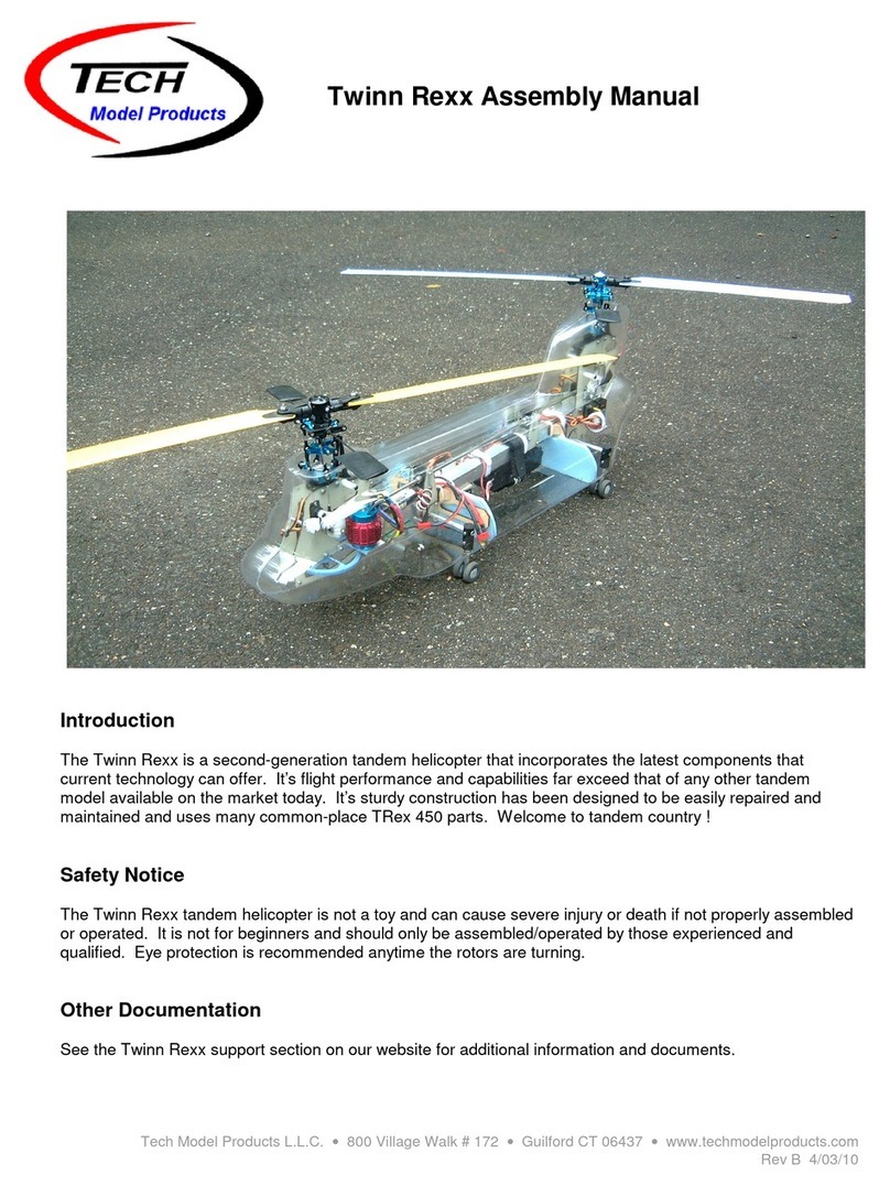
TECH Twinn Rexx CH47 User manual

Tech Model Products L.L.C. •www.techmodelproducts.com •Rev A 5/20/18
Twinn Rexx CH47 Body Assembly Instructions
See this manual online at www.techmodelproducts.com/support.htm
This is a sport scale replica of the famous CH47 Chinook tandem rotor helicopter. It is designed to attach to
the Twinn Rexx frame with only four screws. The body halves can be screwed/taped together or a
combination of both. A cutout or hatch underneath allows access to the battery etc. The body is about
68.5cm (27 inches) and weighs 230 grams (8.2 ounces) unpainted.
Kit Contents: Qty:
Left body panel 1
Right body panel 1
Body to frame mounting hardware 1
Body support kit 1
Tools Required: Materials Required:
Lexan scissors (curved) Acetone (used as glue)
Drill with #34 bit (0.11") & 2mm bit (0.078") 5 minute epoxy
Rotary tool - carbide cutter, sanding drums Wood glue/White glue (optional)
Hobby knife #11 blade Tape
Paper punch Thin CA
2mm tap and drill set (0.062" drill bit) M2x6 button head screws
Sanding block 220 grit

Tech Model Products L.L.C. •www.techmodelproducts.com •Rev A 5/20/18
1. Remove the body halves from the formed panels. Using a sharp scissor, cut around the
perimeter of each body panel leaving about 1 cm of excess plastic. With a curved scissor, cut the
remaining plastic away from the body panels. Take your time. Do not under cut - tend towards
removing less material than needed which can later be sanded away easily. See Figure 1.
2. Sand the body edges smooth. Using a sanding block with fine sandpaper (225), gently sand away
any excess plastic from the edges. Using a flat wood block on the inside of the body will help get a
perfect edge. Again, take your time. A rotary tool fitted with a sanding drum will work as well but it is
easy to undercut. Tip - Use a rotary tool with speed control and slow it down.
3. Cut the landing gear holes. Using a rotary tool with a carbide cutter, cut each landing gear hole
out. Use a sanding drum to finish it smooth. Tip - Make the holes a bit larger than marked. A trim
ring can be used later to cover it up. A larger hole will help reduce the possibility of damage in the
event of a crash. . See Figure 2.
4. Cut the tower holes. Using a rotary tool with a carbide cutter, cut each tower hole as marked (or as
desired). Use a sanding drum to finish smooth.
5. Make the plastic washers. Using scrap material, make about a dozen (12) plastic washers by first
drilling holes and then punching out the washer with a paper punch. Use a #34 (0.11") drill bit. See
Figure 3.
6. Drill the body to frame mounting holes. Attach the four (4) Nylon standoffs to the frame with the
4-40 x 3/8 screws. Hold one of the body panels to the frame and verify that the frame mounting
holes line up with the drill marks on the body. Adjust as required and re-mark if needed (or as
desired).
Using a hobby knife with a #11 blade, make a pilot hole on each drill mark by rotating the knife point
on the center of the mark. Drill the holes using a #34 (0.11") drill bit. See Figure 3.
Attach a body panel to the frame using two 4-40 x 3/8 button head screws. Use two (2) plastic
washers inside the body to shim it outward. Note: The rear strut mounts (TW-402) may need to be
trimmed to clear the body (bottom rear section of the strut mounts).
The rear body mounting holes may need to be widened a bit (slotted) to allow adjustments to the
drive shaft.
Now repeat the above steps for the other body panel. Be sure the two body halves line up. The
mounting hole locations may require adjustment and/or more washers may be needed.
7. Attach a plastic washer to each body mounting hole. For strength, attach a plastic washer to
the inside of each body mounting hole using Acetone as a glue. Just center the washer around the
hole and apply a small drop of Acetone so it flows between the washer and body. Too much can eat
away at the body. Practice on scrap first. Allow to cure.
8. Make the body joining tabs. Using scrap material, make about fifteen (15) plastic body joining
tabs. Each tab consists of a rectangular piece 1 cm wide by 2 cm long with two stacked circular
discs glued to it. Glue with Acetone. The circular discs are made with a paper punch. See Figure 4.
Use a hobby knife with a #11 blade and make a pilot hole on the tab. The hole should be centered
on the tab's disc. Drill the holes using a (0.062") drill bit. Tap each tab hole with a 2mm tap.
9. Attach the body joining tabs. Glue the tabs to one side of the body using Acetone or thin CA (CA
is preferred here). Each tab is positioned such that the center of the discs are about 3mm from the
edge of the body. The tabs should be bent and shaped to conform to the body for best results. Use
Figure 4 as a guide for the tab locations. More or less tabs can be used as desired. Also, tape can
be used in some areas instead of tabs. See Figure 5.

Tech Model Products L.L.C. •www.techmodelproducts.com •Rev A 5/20/18
10. Drill the body joining holes. Mount the body halves to the frame with the four 4-40 screws. Verify
that they are in the correct position and butt together properly. Now use tape to join them along the
entire seam so they will stay in position while marking the holes for drilling.
Mark the locations of the holes at each tab. Take your time.
Use a hobby knife with a #11 blade and make a pilot hole on each mark. Drill the holes using a 2mm
drill bit. A slightly larger drill can be used to compensate for misalignment. See Figure 5.
11. Assemble the plastic and CF (or wood) body supports. The wood body parts are assembled as
shown using 5 minute epoxy or wood glue. See Figure 6.
The plastic and CF version is included with the latest kits and replaces the wood parts.
Each bracket gets a CF rod centered through the holes and glued with CA. When cured, coat the
joints with epoxy. The remaining four plates get glued with CA to the end of each rod. The foam
supports attach to the plates with servo tape or epoxy. See Figure 6A.
12. Attach the plastic and CF (or wood) body supports to the frame. Attach the front and rear body
supports to the frame with two (2) plastic cable ties on each. The rear support is taller. See Figures
6B, 7 for the approximate locations.
13. Attach the foam body supports. Cut two each of the front and rear foam supports using the
template provided. They are cut from 1/4" foam board. See Figure 8.
Mount one of the body halves to the frame with two 4-40 screws. Attach the front and rear foam
supports to the plates (or plywood) using epoxy or servo tape. Position the foam supports such that
they touch the inside and bottom surfaces of the body. Repeat the above procedure for the other
body panel.
14. Cut the battery access hole in the bottom of the body. The exact location and size of the access
hole depends on where the battery is mounted. Generally, a 5 cm wide hole by about 15 cm long
hole will be adequate. Determine the best location for the hole and cut it out. Rounded corners are
recommended. See Figure 9.
15. Final mounting to the frame. The body halves are mounted to the frame with four (4) 4-40 screws.
The body halves are attached to each other using M2x6 button head screws. Tip - A very small drop
of thin CA applied to the screw threads, and allowed to dry, will work as a thread locker.
16. Finishing. The body is made of PETG plastic which is compatible with most types of modeling
paints. The surface should be lightly sanded with a 400 grit sandpaper and then sprayed with one or
two light coats of paint. Avoid using primer if possible since it adds weight. Paints like Krylon brand
come in a variety of camouflage colors, are very easy to apply and dry in a few minutes.
17. Engines. See the full scale CH47 drawings on the Twinn Rexx support page. The engines can be
carved from light weight Styrofoam etc. and glued to the body. An engines kit is available on our
web store.

Tech Model Products L.L.C. •www.techmodelproducts.com •Rev A 5/20/18
Figure 1
Figure 2

Tech Model Products L.L.C. •www.techmodelproducts.com •Rev A 5/20/18
Figure 3
Figure 4
Figure 5
Figure 6
2 cm
1cm
3mm

Tech Model Products L.L.C. •www.techmodelproducts.com •Rev A 5/20/18
Figure 6A
Figure 6B

Tech Model Products L.L.C. •www.techmodelproducts.com •Rev A 5/20/18
Figure 7
Figure 8
Figure 9
Table of contents
Other TECH Toy manuals
Popular Toy manuals by other brands

Fisher-Price
Fisher-Price CFM96 instruction sheet

LEGO
LEGO DC Comics Super Heroes 76085 Assembly instructions

Kettler
Kettler 8881?900 Assembly instructions
MTHTrains
MTHTrains RailKing RealTrax manual

Faller
Faller OLD-TOWN TOWER WITH WALL 232171 Assembly instructions
Parkside
Parkside PP 1500 A1 Operation and safety notes
