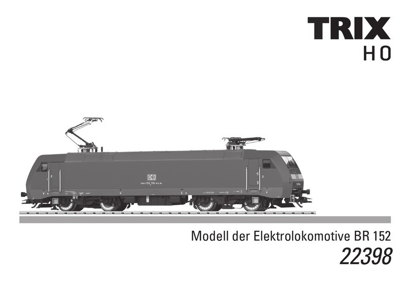
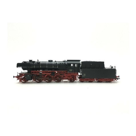
Trix C 5/6 Elefant Series User manual

D GB F
USA NL Modell der Dampflokomotive Serie C 5/6 „Elefant“
22925

2
Hinweis
Bei bestimmten Gleissituationen kann es durch das Bremsge-
stänge unter der Lok zu vereinzelten Problemen kommen. Wir
empfehlen dann, das Bremsgestänge für den Fahrbetrieb zu
demontieren.
Note
With certain track situations, the brake rigging under the
locomotive may cause sporadic problems. In this case, we
recommend removing the brake rigging when operating the
locomotive.
Remarque
Dans certaines situations sur le voies, on peut avoir des
problèmes occasionnels avec la tige de frein sous la locomotive.
Nous vous recommandons donc de démanteler la tringlerie de
frein pour la conduite.
Opmerking
Bij bepaalde railsituaties kan het mogelijk tot problemen komen
i.v.m. de remstangen onder de loc. Daarom is het aan te bevelen
de remstangen voor het rijbedrijf te demonteren.

3
Inhaltsverzeichnis: Seite
Informationen zum Vorbild 4
Hinweise zur Inbetriebnahme 6
Sicherheitshinweise 8
Wichtige Hinweise 8
Multiprotokollbetrieb 8
Schaltbare Funktionen 11
Parameter/Register 12
Ergänzendes Zubehör 28
Wartung und Instandhaltung 31
Ersatzteile 37
Table of Contents: Page
Information about the prototype 4
Notes about using this model for the first time 6
Safety Notes 13
Important Notes 13
Multi-Protocol Operation 13
Controllable Functions 16
Parameter/Register 17
Complementary accessories 28
Service and maintenance 31
Spare Parts 37
Sommaire : Page
Informations concernant la locomotive réelle 5
Indications relatives à la mise en service 6
Remarques importantes sur la sécurité 18
Information importante 18
Mode multiprotocole 18
Fonctions commutables 21
Paramètre/Registre 22
Accessoires complémentaires 28
Entretien et maintien 31
Pièces de rechange 37
Inhoudsopgave: Pagina
Informatie van het voorbeeld 5
Opmerking voor de ingebruikname 6
Veiligheidsvoorschriften 23
Belangrijke aanwijzing 23
Multiprotocolbedrijf 23
Schakelbare functies 26
Parameter/Register 27
Aanvullende toebehoren 28
Onderhoud en handhaving 31
Onderdelen 37

4
Informationen zum Vorbild
Nach der Übernahme der Gotthardbahn im Jahr 1909 durch die
Schweizerischen Bundesbahnen (SBB) zeigte sich schnell die
Notwendigkeit zur Beschaffung einer Lokomotive mit größerer
Leistungsfähigkeit, um den Betrieb auf den Steilrampen am
Gotthard und den Zufahrtsstrecken im Flachland wirtschaftlicher
gestalten zu können. Neben der Bespannung von Güterzügen
sollten die Loks auch vor Schnellzügen auf den Steilrampen
eingesetzt werden können, was neben hoher Zugkraft auch eine
Höchstgeschwindigkeit von 65 km/h erforderte.
Schon 1913 standen die zwei Prototypen 2901 und 2902 der Bau-
art C 5/6 zur Erprobung bereit. Sie waren mit einem Vierzylinder-
Triebwerk und einfacher Dampfdehnung ausgerüstet, welches
sich aber nicht sonderlich bewährte. Daher griff man bei den
Serienloks auf die guten Erfahrungen mit dem Triebwerk der
C 4/5-Lokomotiven der Serie 2701–32 zurück und baute ein
Vierzylinder-Verbund-Triebwerk nach Von-Borries ein. Dabei
wirkten die beiden innenliegenden Hochdruckzylinder auf den
zweiten Treibradsatz, die äußeren Niederdruckzylinder hingegen
auf den dritten Treibradsatz. Um einen guten Kurvenlauf zu ge-
währleisten, besaß der hinterste Kuppelradsatz 25 mm Spiel und
beim mittleren Triebradsatz waren die Spurkränze geschwächt.
Zwischen 1913 und 1917 wurden insgesamt 28 Serienmaschinen
mit den Nummern 2951-2978 in Dienst gestellt, wobei die 2978
gleichzeitig die letzte an die SBB abgelieferte normalspurige
Dampflok bildete.
Information about the Prototype
After the Swiss Federal Railways (SBB) took over the Gotthard
Line in 1909, it quickly became apparent that locomotives had
to be acquired with greater performance in order to make ope-
rations on the steep grades on the Gotthard and the approach
lines on flat territory more efficient. In addition to serving as
motive power for freight locomotives, these locomotives also
had to be capable of pulling express trains on the steep grades,
which required a maximum speed of
65 km/h / 41 mph in addition to high pulling power.
The two prototypes, road numbers 2901 and 2902, of the
class C 5/6 were available for testing as early as 1913. They were
equipped with four-cylinder running gear and simple expansion,
which did not turn out particularly well. On the regular produc-
tion locomotives, recourse was therefore made to the good
experience with the running gear for the C 4/5 locomotives in the
series 2701–32 and four-cylinder compound running gear based
on Von-Borries was installed. In this instance, the two inboard
high-pressure cylinders drove the second driving wheel set,
and the outboard low-pressure cylinders drove the third driving
wheel set. The rear coupled wheel set had 25 mm / 1 inch side
play and the treads on the center wheel set were made narro-
wer to ensure good running on curves. Between 1913 and 1917,
28 regular production units were placed into service with the
road numbers 2951-2978, whereby road number 2978 was also
the last standard gauge steam locomotive delivered to the SBB.

5
Informations concernant la locomotive réelle
Après la reprise en 1909 de la ligne du Saint-Gothard par les chemins
de fer fédéraux suisses (CFF), la nécessité de l’acquisition d‘une lo-
comotive plus performante capable d’assurer de façon plus rentable
l’exploitation sur les rampes à forte déclivité du Saint-Gothard et les
voies d’accès en plaine se fit rapidement sentir. Les locomotives
devaient être capables de remorquer non seulement des trains
marchandises, mais également des trains rapides sur les rampes
à forte déclivité, ce qui outre une grande force de traction exigeait
également une vitesse maximale de 65 km/h.
Dès 1913, les deux prototypes 2901 et 2902 type C 5/6 étaient
disponibles pour des essais. Ils étaient équipés d’un moteur à
quatre cylindres à simple expansion ce qui ne s’avéra toutefois
pas très satisfaisant. Pour les locomotives de séries, on se re-
porta donc aux expériences probantes réalisées avec le moteur
des locomotives C 4/5 de la série 2701-32 et équipa les machines
d’un moteur compound à quatre cylindres d’après Von-Borries.
Les deux cylindres à haute pression situés à l‘intérieur agissai-
ent ainsi sur le deuxième essieu moteur, tandis que les cylindres
extérieurs à basse pression agissaient sur le troisième essieu
moteur. Afin d’assurer une bonne inscription en courbe, l’essieu
couplé le plus à l’arrière avait un jeu de 25 mm et les boudins
de roues avaient été diminués sur le troisième essieu moteur.
Entre 1913 et 1917, 28 machines de série au total, portant les
numéros 2951 à 2978, furent mises en service, la 2978 représen-
tant simultanément la dernière locomotive à vapeur pour voie
normale livrée aux CFF.
Informatie van het voorbeeld
Na de overname van de Gotthardbahn in 1909 door de Zwitserse
Bundesbahn (SBB), werd al snel duidelijk dat de aanschaf nodig
was van een locomotief met een groter prestatievermogen, om
die op de steile hellingen van de Gotthard in te zetten en om de
treintrajecten in de laaglanden zuinig te kunnen organiseren.
Naast het trekken van goederentreinen moesten de locomotie-
ven ook voor sneltreinen op de steile hellingen kunnen worden
ingezet, wat naast een grotere trekkracht ook een topsnelheid
van 65 km/u vereiste.
Reeds in 1913 stonden de twee prototypes 2901 en 2902 van de
serie C 5/6 ter beschikking om getest te worden. Ze waren met
een viercilinderaandrijving en enkelvoudige expansie uitgerust,
die zich echter niet speciaal kon bewijzen. Daarom greep men
bij de serielocomotieven terug naar de goede ervaringen met
de aandrijving van de C 4/5-locomotieven van de serie 2701–32
en werd een viercilinderverbindingsaandrijving volgens Von-
Borries ingebouwd. Hier werkten beide inwendige hogedruk-
cilinders op het tweede aandrijvingswielstel, de uitwendige
lagedrukcilinders daarentegen op het derde aandrijvingswie-
lstel. Om een goede loop in de bochten te verzekeren, had het
achterste koppelingswielstel 25 mm speling en bij het middelste
aandrijvingswielstel waren de wielkransen verzwakt. Tussen
1913 en 1917 werden in totaal 28 seriemachines met de nummers
2951-2978 in dienst gesteld, waarbij de 2978 tegelijk de laatste,
aan SBB geleverde stoomlocomotief voor normaalspoor was.

6
Die Kurzkupplung zwischen Lok und Tender ist verstellbar. Der
kurze Abstand ist für den Fahrbetrieb nicht geeignet.
Zum fahren oder Verpacken den langen Abstand einstellen.
Um den Abstand zu verändern, die Lok und den Tender auf dem
geraden Gleis stehend vorsichtig zusammenschieben bzw.
auseinanderziehen.
L’attelage court entre loco et tender est réglable. L’espace court
ne convient pas pour l’exploitation.
Pour faire rouler ou emballer les engins, régler l’espace long.
Pour modifier l’écart, poser loco et tender sur un élément de
voie droit et les pousser délicatement l’un vers l’autre ou les
éloigner, selon le cas.
De kortkoppeling tussen loc en tender is verstelbaar. De korte
afstand is niet geschikt voor het rijbedrijf. Voor het rijden en
verpakken dient de langere afstand ingesteld te worden. Om de
afstand te veranderen, de loc en tender op een recht railstuk
plaatsen en voorzichtig naar elkaar schuiven resp. uit elkaar
trekken.
The close coupling between the locomotive and tender is
adjustable. The short spacing is not suitable for running the
locomotive.
Set the long spacing for running or packing the locomotive.
In order to change the spacing, place the locomotive and tender
on straight track and carefully push them together or pull them
away from each other.

7

8
Sicherheitshinweise
• DieLokdarfnurmiteinemdafürbestimmtenBetriebssystem
eingesetzt werden.
• Analogmax.15Volt=,digitalmax.22Volt~.
• DieLokdarfnurauseinerLeistungsquelleversorgtwerden.
• BeachtenSieunbedingtdieSicherheitshinweiseinder
Bedienungsanleitung zu Ihrem Betriebssystem.
• FürdenkonventionellenBetriebderLokmussdasAnschluss-
gleis entstört werden. Dazu ist das Entstörset
611 655 zu verwenden. Für Digitalbetrieb ist das Entstörset
nicht geeignet.
• ACHTUNG! Funktionsbedingte scharfe Kanten und Spitzen.
• SetzenSiedasModellkeinerdirektenSonneneinstrahlung,
starken Temperaturschwankungen oder hoher Luftfeuchtig-
keit aus.
• VerbauteLED`sentsprechenderLaserklasse1nachNormEN
60825-1.
Wichtige Hinweise
• DieBedienungsanleitungunddieVerpackungsindBestand-
teile des Produktes und müssen deshalb aufbewahrt sowie
bei Weitergabe des Produktes mitgegeben werden.
• FürReparaturenoderErsatzteilewendenSiesichbittean
Ihren Trix-Fachhändler.
• GewährleistungundGarantiegemäßderbeiliegendenGaran-
tieurkunde.
• Entsorgung:www.maerklin.com/en/imprint.html
• DervolleFunktionsumfangistnurunterTrixSystems,DCC
und unter mfx verfügbar.
• Eingebaute,fahrtrichtungsabhängigeStirnbeleuchtung.
Im Digitalbetrieb schaltbar.
• BefahrbarerMindestradius360mm.
Multiprotokollbetrieb
Analogbetrieb
Der Decoder kann auch auf analogen Anlagen oder Gleisab-
schnitten betrieben werden. Der Decoder erkennt die analoge
Gleichspannung (DC) automatisch und passt sich der analogen
Gleisspannung an. Es sind alle Funktionen, die unter mfx oder
DCC für den Analogbetrieb eingestellt wurden aktiv (siehe
Digitalbetrieb).
Digitalbetrieb
Der Decoder ist ein Multiprotokolldecoder. Der Decoder kann unter
folgendenDigital-Protokolleneingesetztwerden:mfxoderDCC.
Das Digital-Protokoll mit den meisten Möglichkeiten ist das
höchstwertige Digital-Protokoll. Die Reihenfolge der Digital-
ProtokolleistinderWertungfallend:
Priorität1:mfx
Priorität2:DCC
Priorität3:DC
Hinweis: Werden zwei oder mehrere Digital-Protokolle am Gleis
erkannt, übernimmt der Decoder automatisch das höchstwertige
Digital-Protokoll, z.B. mfx/DCC, somit wird das mfx-Digital-Proto-
koll vom Decoder übernommen.
Hinweis: Beachten Sie, dass nicht alle Funktionen in allen
Digital-Protokollen möglich sind. Unter mfx und DCC können
einige Einstellungen von Funktionen, welche im Analog-Betrieb
wirksam sein sollen, vorgenommen werden.

9
Hinweise zum Digitalbetrieb
• DiegenaueVorgehensweisezumEinstellenderdiversen
Parameter entnehmen Sie bitte der Bedienungsanleitung
Ihrer Mehrzug-Zentrale.
• DieabWerkeingestelltenWertesindfürmfxgewählt,so
dass ein bestmöglichstes Fahrverhalten gewährleistet ist.
Für andere Betriebssysteme müssen gegebenenfalls Anpas-
sungen getätigt werden.
• DerBetriebmitgegenpoligerGleichspannungimBremsab-
schnitt ist mit der werkseitigen Einstellung nicht möglich. Ist
diese Eigenschaft gewünscht, so muss auf den konventio-
nellenGleichstrombetriebverzichtetwerden(CV29/Bit2=0).
mfx-Protokoll
Adressierung
• KeineAdresseerforderlich,jederDecodererhälteineeinma-
lige und eindeutige Kennung (UID).
• DerDecodermeldetsichaneinerCentralStationoderMobile
Station mit seiner UID automatisch an.
• NameabWerk:C 5/6 2965 SBB
Programmierung
• DieEigenschaftenkönnenüberdiegrascheOberächeder
Central Station bzw. teilweise auch mit der Mobile Station
programmiert werden.
• EskönnenalleCongurationVariablen(CV)mehrfachgele-
sen und programmiert werden.
• DieProgrammierungkannentwederaufdemHaupt-oder
dem Programmiergleis erfolgen.
• DieDefaulteinstellungen(Werkseinstellungen)können
wieder hergestellt werden.
• Funktionsmapping:FunktionenkönnenmitHilfederCentral
Station 60212 (eingeschränkt) und mit der Central Station
60213/60214/60215 beliebigen Funktionstasten zugeordnet
werden (Siehe Hilfe in der Central Station).
DCC-Protokoll
Adressierung
• KurzeAdresse–LangeAdresse–Traktionsadresse
• Adressbereich:
1 - 127 kurze Adresse, Traktionsadresse
1 - 10239 lange Adresse
• JedeAdresseistmanuellprogrammierbar.
• KurzeoderlangeAdressewirdüberdieCVsausgewählt.
• EineangewandteTraktionsadressedeaktiviertdieStandard-
Adresse.

10
Programmierung
• DieEigenschaftenkönnenüberdieCongurationsVariablen
(CV) mehrfach geändert werden.
• DieCV-NummerunddieCV-Wertewerdendirekteingegeben.
• DieCVskönnenmehrfachgelesenundprogrammiertwerden
(Programmierung auf dem Programmiergleis).
• DieCVskönnenbeliebigprogrammiertwerden(Programmie-
rung auf dem Hauptgleis PoM). PoM ist nur bei den in der CV-
Tabelle gekennzeichneten CV möglich. Die Programmierung
auf dem Hauptgleis (PoM) muss von Ihrer Zentrale unterstützt
werden (siehe Bedienungsanleitung ihres Gerätes).
• DieDefaulteinstellungen(Werkseinstellungen)können
wieder hergestellt werden.
• 14bzw.28/126Fahrstufeneinstellbar.
• AlleFunktionenkönnenentsprechenddemFunktionsmapping
geschaltet werden.
• WeitereInformation,sieheCV-TabelleDCC-Protokoll.
Es wird empfohlen, die Programmierungen grundsätzlich auf
dem Programmiergleis vorzunehmen.
Logische Funktionen
Anfahr-/Bremsverzögerung
• DieBeschleunigungs-undBremszeitkanngetrenntvonei-
nander eingestellt werden.
• DielogischeFunktionsabschaltungABVkannüberdas
Funktionsmapping auf jede beliebige Funktionstaste gelegt
werden.

11
Schaltbare Funktionen
Stirnbeleuchtung an Funktion f0 Funktion f0
Rauchgenerator an Funktion 1 Funktion f1 Funktion f1
Betriebsgeräusch — Funktion 2 Funktion f2 Funktion f2
Geräusch:Lokpfeife — Funktion 3 Funktion f3 Funktion f3
ABV, aus — Funktion 4 Funktion f4 Funktion f4
Geräusch:Bremsenquietschenaus — Funktion 5 Funktion f5 Funktion f5
Führerstandsbeleuchtung — Funktion 6 Funktion f6 Funktion f6
Geräusch:Rangierpff — Funktion 7 Funktion f7 Funktion f7
Geräusch:Dampfablassen — Funktion 8 Funktion f8 Funktion f8
Geräusch:Kohleschaufeln — — Funktion f9 Funktion f9
Geräusch:Kipprost — — Funktion f10 Funktion f10
Geräusch:Luftpumpe — — Funktion f11 Funktion f11
Geräusch:Wasserpumpe — — Funktion f12 Funktion f12
Geräusch:Injektor — — Funktion f13 Funktion f13
Rangiergang — — Funktion f14 Funktion f14
STOP mobile station
15
f0 f8 f0f8
f0 - f3 f4 - f7

12
CV Bedeutung Wert DCC ab Werk
1 Adresse 1 - 127 3
2 PoM Minimalgeschwindigkeit 0 - 255 5
3 PoM Anfahrverzögerung 0 - 255 15
4 PoM Bremsverzögerung 0 - 255 15
5 PoM Maximalgeschwindigkeit 0 - 255 160
8 Werkreset/Herstellerkennung 8 131
13 PoM Funktionen F1 - F8 im Analogbetrieb 0 - 255 0
14 PoM Funktionen F9 - F15 und Licht im Analogbetrieb 0 - 255 1
17 Erweiterte Adresse (oberer Teil) CV29,Bit5=1 192
18 Erweiterte Adresse (unterer Teil) CV29,Bit5=1 128
19 Traktionsadresse 0 - 255 0
21 PoM Funktionen F1 - F8 bei Traktion 0 - 255 0
22 PoM Funktionen F9 - F15 und Licht bei Traktion 0 - 255 0
29
Bit0:UmpolungFahrtrichtung
Bit1:AnzahlFahrstufen14oder28/128*
Bit2:DCCBetriebmitBremsstrecke
(kein Analogbetrieb möglich)
Bit5:Adressumfang7Bit/14Bit
0 / 1
0 / 2
0 / 4
0 / 32
0, 1, 2, 3, 4, 5, 6, 7,
32, 34, 35, 36, 37,
38, 39 6
63 Lautstärke 0 - 255 255
* FahrstufenamLokdecoderundamSteuergerätmüssenübereinstimmen,essindsonstFehlfunktionenmöglich.

13
• Built-inheadlightsthatchangeoverwiththedirectionof
travel. They can be turned on and off in digital operation.
• Minimumradiusforoperationis360mm/14-3/16“.
Multi-Protocol Operation
Analog Operation
This decoder can also be operated on analog layouts or areas
of track that are analog. The decoder recognizes alternat-
ing current (DC) and automatically adapts to the analog track
voltage. All functions that were set under mfx or DCC for analog
operation are active (see Digital Operation).
Digital Operation
The decoders are multi-protocol decoders. These decoders can
beusedunderthefollowingdigitalprotocols:mfxorDCC.
The digital protocol with the most possibilities is the highest
order digital protocol. The sequence of digital protocols in
descendingorderis:
Priority1:mfx
Priority2:DCC
Priority3:DC
Note: If two or more digital protocols are recognized in the track,
the decoder automatically takes on the highest order digital
protocol,example:mfx/DCC;thedecodertakesonthemfxdigital
protocol (see previous table).
Note: Please note that not all functions are possible in all digital
protocols. Several settings for functions, which are supposed to
be active in analog operation, can be done under mfx and DCC.
Safety Notes
• Thislocomotiveisonlytobeusedwiththeoperatingsystem
it is designed for.
• Analogmax.15voltsDC,digitalmax.22voltsAC.
• Thislocomotivemustneverbesuppliedwithpowerfrom
more than one power pack.
• Pleasemakenoteofthesafetynotesintheinstructionsfor
your operating system.
• Thefeedertrackmustbeequippedtopreventinterference
with radio and television reception, when the locomotive is
to be run in conventional operation. The 611 655 interference
suppression set is to be used for this purpose. The interfe-
rence suppression set is not suitable for digital operation.
• WARNING! Sharp edges and points required for operation.
• Donotexposethemodeltodirectsunlight,extremechanges
in temperature, or high humidity.
• TheLEDsinthisitemcorrespondtoLaserClass1according
to Standard EN 60825-1.
Important Notes
• Theoperatinginstructionsandthepackagingareacompo-
nent part of the product and must therefore be kept as well as
transferred along with the product to others.
• PleaseseeyourauthorizedTrixdealerforrepairsorspare
parts.
• Thewarrantycardincludedwiththisproductspeciesthe
warranty conditions.
• Disposing:www.maerklin.com/en/imprint.html
• ThefullrangeoffunctionsisonlyavailableunderTrixSys-
tems and under DCC.

14
Notes on digital operation
• Theoperatinginstructionsforyourcentralunitwillgiveyou
exact procedures for setting the different parameters.
• Thevaluessetatthefactoryhavebeenselectedformfxin
order to guarantee the best possible running characteristics.
Adjustments may have to be made for other operating
systems.
• Thesettingdoneatthefactorydoesnotpermitoperationwith
opposite polarity DC power in the braking block. If you want
this characteristic, you must do without conventional DC
poweroperation(CV29/Bit2=0).
mfx Protocol
Addresses
• Noaddressisrequired;eachdecoderisgivenaone-time,
unique identifier (UID).
• ThedecoderautomaticallyregistersitselfonaCentralStation
or a Mobile Station with its UID.
• Namesetatthefactory:C 5/6 2965 SBB
Programming
• Thecharacteristicscanbeprogrammedusingthegraphic
screen on the Central Station or also partially with the Mobile
Station.
• AlloftheCongurationVariables(CV)canbereadand
programmed repeatedly.
• Theprogrammingcanbedoneeitheronthemaintrackorthe
programming track.
• Thedefaultsettings(factorysettings)canbeproduced
repeatedly.
• Functionmapping:Functionscanbeassignedtoanyofthe
function buttons with the help of the 60212 Central Station
(with limitations) and with the 60213/60214/60215 Central Sta-
tion (See help section in the Central Station).
DCC Protocol
Addresses
• Shortaddress–longaddress–multipleunitaddress
• Addressrange:
1 - 127 for short address and multiple unit address,
1 - 10239 for long address
• Everyaddresscanbeprogrammedmanually.
• AshortoralongaddressisselectedusingtheCVs.
• Amultipleunitaddressthatisbeinguseddeactivatesthe
standard address.

15
Programming
• Thecharacteristicscanbechangedrepeatedlyusingthe
Configuration Variables (CV).
• TheCVnumbersandtheCVvaluesareentereddirectly.
• TheCVscanbereadandprogrammedrepeatedly.(Program-
ming is done on the programming track.)
• TheCVscanbeprogrammedinanyorderdesired.(Program-
ming can be done on the main track PoM). The PoM can only
be done with those designated in the CV table. Programming
on the main track PoM must be supported by your central
controller (Please see the description for this unit.).
• Thedefaultsettings(factorysettings)canbeproduced
repeatedly.
• 14/28or126speedlevelscanbeset.
• Allofthefunctionscanbecontrolledaccordingtothefunc-
tion mapping (see CV description).
• SeetheCVdescriptionfortheDCCprotocolforadditional
information.
We recommend that in general programming should be done on
the programming track.
Logic Functions
Acceleration/Braking Delay
• Theaccelerationandbrakingtimecanbesetseparatelyfrom
each other.
• ThelogicfunctionABVcanbeassignedtoanyfunction
button by using the function mapping.

16
Controllable Functions
Headlights on Function f0 Function f0
Smoke generator on Function 1 Function f1 Function f1
Operating sounds — Function 2 Function f2 Function f2
Soundeffect:Locomotivewhistle — Function 3 Function f3 Function f3
ABV, off — Function 4 Function f4 Function f4
Soundeffect:Squealingbrakesoff — Function 5 Function f5 Function f5
Engineer‘s cab lighting — Function 6 Function f6 Function f6
Soundeffect:Switchingwhistle — Function 7 Function f7 Function f7
Soundeffect:Blowingoffsteam — Function 8 Function f8 Function f8
Soundeffect:Coalbeingshoveled — — Function f9 Function f9
Soundeffect:Ashgrate — — Function f10 Function f10
Soundeffect:Airpump — — Function f11 Function f11
Soundeffect:Waterpump — — Function f12 Function f12
Soundeffect:Injector — — Function f13 Function f13
Low speed switching range — — Function f14 Function f14
STOP mobile station
15
f0 f8 f0f8
f0 - f3 f4 - f7

17
CV Discription DCC Value Factory-Set
1 Address 1 - 127 3
2 PoM Minimum Speed 0 - 255 5
3 PoM Acceleration delay 0 - 255 15
4 PoM Braking delay 0 - 255 15
5 PoM Maximum speed 0 - 255 160
8 Factory Reset / Manufacturer Recognition 8 131
13 PoM Functions F1 - F8 in analog operation 0 - 255 0
14 PoM Functions F9 - F15 and lights in analog operation 0 - 255 1
17 Extended address (upper part) CV29,Bit5=1 192
18 Extended address (lower part) CV29,Bit5=1 128
19 Multiple Unit Address 0 - 255 0
21 PoM Functions F1 - F8 on Multiple Unit 0 - 255 0
22 PoM Functions F9 - F15 and lights on Multiple Unit 0 - 255 0
29
Bit0:Reversingdirection
Bit1:Numberofspeedlevels14or28/128*
Bit2:DCCoperationwithbrakingarea
(no analog operation possible)
Bit5:Addresslength7Bit/14Bit
0 / 1
0 / 2
0 / 4
0 / 32
0, 1, 2, 3, 4, 5, 6, 7,
32, 34, 35, 36, 37,
38, 39
6
63 Volume 0 - 255 255
*Thespeedlevelsonthelocomotivedecoderandonthecontrollermustagreewitheachother;otherwise,youmayhavemalfunctions.

18
Remarques importantes sur la sécurité
• Lalocomotivenepeutêtreutiliséequ‘aveclesystème
d‘exploitation indiqué.
• Analogiquemax.15Volt=,digitalmax.22Volt~.
• Lalocomotivenepeutpasêtrealimentéeélectriquementpar
plus d‘une source de courant à la fois.
• Ilestimpératifdetenircomptedesremarquessurla
sécurité décrites dans le mode d‘emploi de votre système
d‘exploitation.
•
Pour l’exploitation de la locomotive en mode conventionnel, la
voie de raccordement doit être déparasitée. A cet effet, utili-
ser le set de déparasitage réf. 611 655. Le set de déparasitage
ne convient pas pour l’exploitation en mode numérique.
•
ATTENTION! Pointes et bords coupants lors du fonctionnement
du produit.
•
Ne pas exposer le modèle à un ensoleillement direct, à de fortes
variations de température ou à un taux d‘humidité important.
• LesDELinstalléescorrespondentàlaclasselaser1selonla
norme EN 60825-1.
Information importante
• Lanoticed‘utilisationetl’emballagefontpartieintégrantedu
produit;ilsdoiventdoncêtreconservéset,lecaséchéant,
transmis avec le produit.
• Pourtouteréparationouremplacementdepièces,adressez
vous à votre détaillant-spécialiste Trix.
• Garantielégaleetgarantiecontractuelleconformémentau
certificat de garantie ci-joint.
• Elimination:www.maerklin.com/en/imprint.html
• L’intégralitédesfonctionsestdisponibleuniquementen
exploitation Trix Systems, DCC et mfx.
• Feuxdesignalisations‘inversantselonlesensdemarche;
feux commutables en exploitation digital.
• Rayonminimald’inscriptionencourbe360mm.
Mode multiprotocole
Mode analogique
On peut aussi faire fonctionner le décodeur sur des installations
ou des sections de voie analogiques. Le décodeur identifie
automatiquement la tension de voie analogique (CC). Toutes les
fonctions qui ont été paramétrée pour le mode analogique sous
mfx ou sous DCC sont actives (voir mode numérique).
Mode numérique
Les décodeur sont des décodeur multiprotocole. Le décodeur peut
êtreutiliséaveclesprotocolesnumériquessuivants:mfx,DCC
Le protocole numérique offrant les possibilités les plus
nombreuses est le protocole numérique à bit de poids fort. La
hiérarchisationdesprotocolesnumériquesestdescendante:
Priorité1:mfx
Priorité2:DCC
Priorité3:
DC
Indication : lorsque deux ou plusieurs protocoles numériques
sont identifiés au niveau de la voie, le décodeur reprend
automatiquement le protocole numérique à bit de poids fort, p.
ex. mfx/DCC. Le protocole numérique mfx est donc repris par le
décodeur (voir tableau antérieur).
Indication : remarquez que toutes les fonctions ne peuvent
pas être actionnées dans tous les protocoles numériques.

19
Sous mfx et sous DCC, il est possible de procéder à quelques
paramétrages de fonctions devant être actives dans le cadre de
l’exploitation analogique.
Remarques relatives au fonctionnement en mode
digital
• Encequiconcernelaprocédurederéglagedesdivers
paramètres, veuillez vous référer au mode d‘emploi de votre
centrale de commande multitrain.
• Lesvaleursparamétréesd’usinesontchoisiespourmfxde
manière à garantir le meilleur comportement de roulement
possible.
Pour d’autres systèmes d’exploitation, ces valeurs devront
éventuellement être adaptées.
• L’exploitationaveccourantcontinudepolaritéinversedans
les sections de freinage n’est pas possible avec le réglage
d’usine. Si cette propriété est désirée, il faut alors renoncer à
l’exploitation conventionnelle en courant continu
(CV29/Bit2=0).
Protocole mfx
Adressage
• Aucuneadressen’estnécessaire,ledécodeurreçoittoute-
fois une identification unique et non équivoque (UID).
• AvecsonUID,ledécodeurindiqueautomatiquementàune
station centrale ou à une station mobile qu’il est connecté.
• Nomencodeeenusine:C 5/6 2965 SBB
Programmation
• Lescaractéristiquespeuventêtreprogramméesparl’inter-
médiaire de la couche graphique de la station centrale, voire
en partie aussi au moyen de la station mobile.
• Touteslescongurationsvariables(CV)peuventêtrelueset
programmées de façon réitérée.
• Laprogrammationpeutêtreréaliséesoitsurlavoieprinci-
pale, soit sur la voie de programmation.
• Lesparamétragespardéfaut(paramétragesusine)peuvent
être rétablis.
• Mappagedesfonctions:lesfonctionspeuventêtreaffectées
à de quelconques touches de fonction au moyen de la station
centrale (60212) (restreinte) et avec la station centrale
60213/60214/60215 (voir Aide au niveau de la station centrale).
Protocole DCC
Adressage
• Adressebrève–adresselongue–adressedetraction.
• Champd’adresse:
1 – 127 adresse brève, adresse de traction
1 – 10239 adresse longue
• Chaqueadresseestprogrammablemanuellement.
• L’adressebrèveoulongueestchoisieparl’intermédiairedesCVs.
• Uneadressedetractionutiliséedésactivel’adressestandard.

20
Programmation
•
Les caractéristiques peuvent être modifiées de façon réitérée
par l’intermédiaire des variables de configuration (CVs).
• Touteslescongurationsvariables(CV)peuventêtrelueset
programmées de façon réitérée.
• Laprogrammationpeutêtreréaliséesoitsurlavoieprinci-
pale, soit sur la voie de programmation.
• LesCVspeuventêtreprogramméeslibrement(programma-
tion de la voie principale (PoM). La PoM n’est possible que
pour les CVs identifiées dans le tableau des CVs. La program-
mation sur la voie principale (PoM) doit être supportée par
votre centrale (voir mode d’emploi de votre appareil).
• Lesparamétragespardéfaut(paramétragesusine)peuvent
être rétablis.
• 14/28,voire126cransdemarchesontparamétrables.
• Touteslesfonctionspeuventêtrecommutéesenfonctiondu
mappage des fonctions (voir le descriptif des CVs).
• Pourtouteinformationcomplémentaire,voirletableaudes
CVs, protocole DCC.
Il est recommandé, de réaliser la programmation, fondamentale-
ment, sur la voie de programmation.
Fonctions logiques
Retard au démarrage / au freinage
• Lestempsd’accélérationetdefreinagepeuventêtreparamé-
trés séparément les uns des autres.
• Parl’intermédiairedumappagedesfonctions,lamisehors
fonction de la fonction logique ABV peut être affectée à
n’importe quelle touche de fonction.
This manual suits for next models
1
Table of contents
Languages:
Other Trix Toy manuals

Trix
Trix H0 BR 18.1 User manual

Trix
Trix BR 984-5 User manual

Trix
Trix 11206 User manual

Trix
Trix BR 234 User manual

Trix
Trix Minitrix 66140 User manual

Trix
Trix BR 23 User manual

Trix
Trix SVT137 User manual

Trix
Trix Ce 6/8III Series User manual

Trix
Trix Baureihe 290 (V90) User manual

Trix
Trix Dm3 User manual
Popular Toy manuals by other brands

Vladimir's Models
Vladimir's Models Yoda Recommendations for assembly

SG Models
SG Models SEA375 Assembly manual

Fisher-Price
Fisher-Price Loving Family Western Horse instructions

USA Trains
USA Trains 44 tonner owner's manual

Thames & Kosmos
Thames & Kosmos Architectural Engineering Experiment manual

Fly Wing
Fly Wing FW450L quick start guide