Franzis PE01 User manual

PORSCHE 911PORSCHE 911
Flat-Six Boxer
engine
Instruction
MANUAL
10+
For Ages
Build your own
working, classic
Porsche 911
flat-six engine
model!
Mehr Franzis-Produkte im Internet www.franzis.de
Designed by John Anson for:
FRANZIS Verlag GmbH
D-85540 Haar bei Munchen
Germany
Item number:
PE01
Trends UK LTD, Greatworth Hall,
Banbury, OX17 2DH. UK
Email: [email protected]
Customer services:
+44 (0)1702 208175

INTRODUCTION ...................................................2
NOTES AND ADVICE............................................6
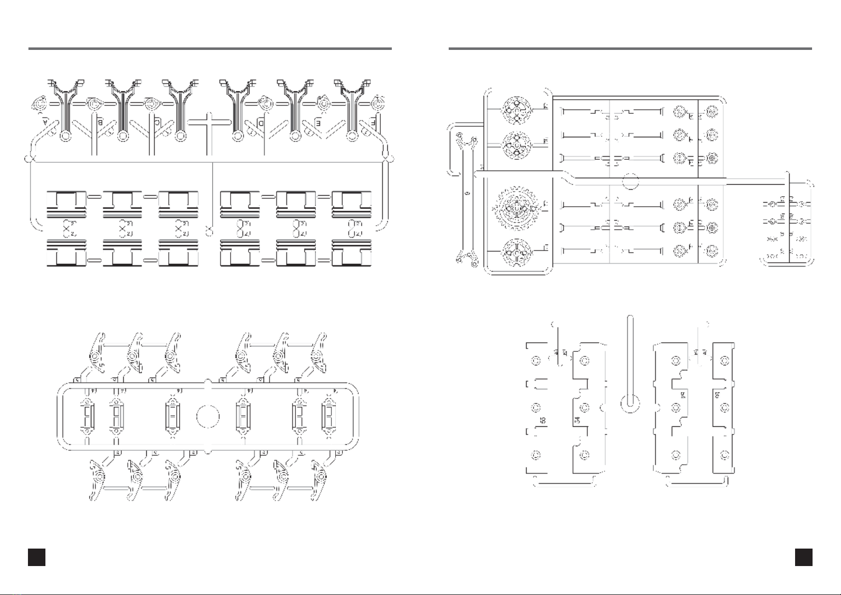
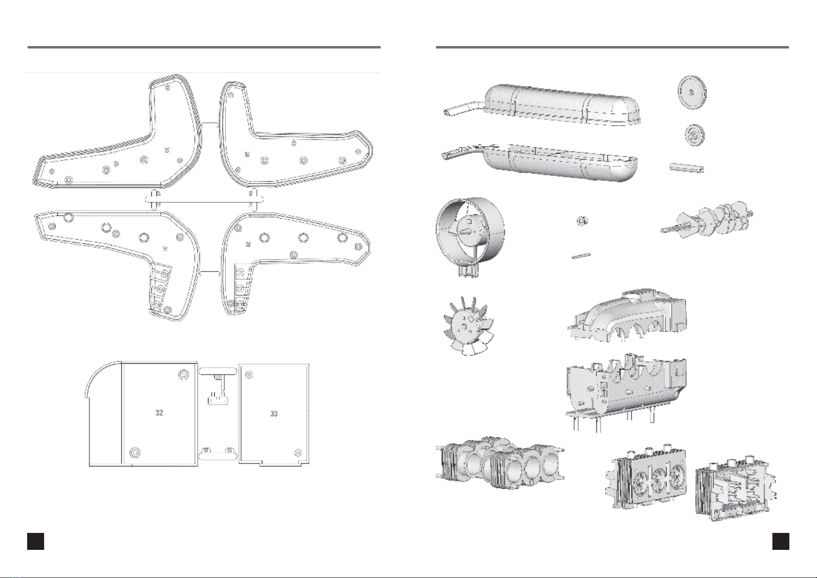
PARTS LIST .........................................................7
ASSEMBLING THE ENGINE...............................15
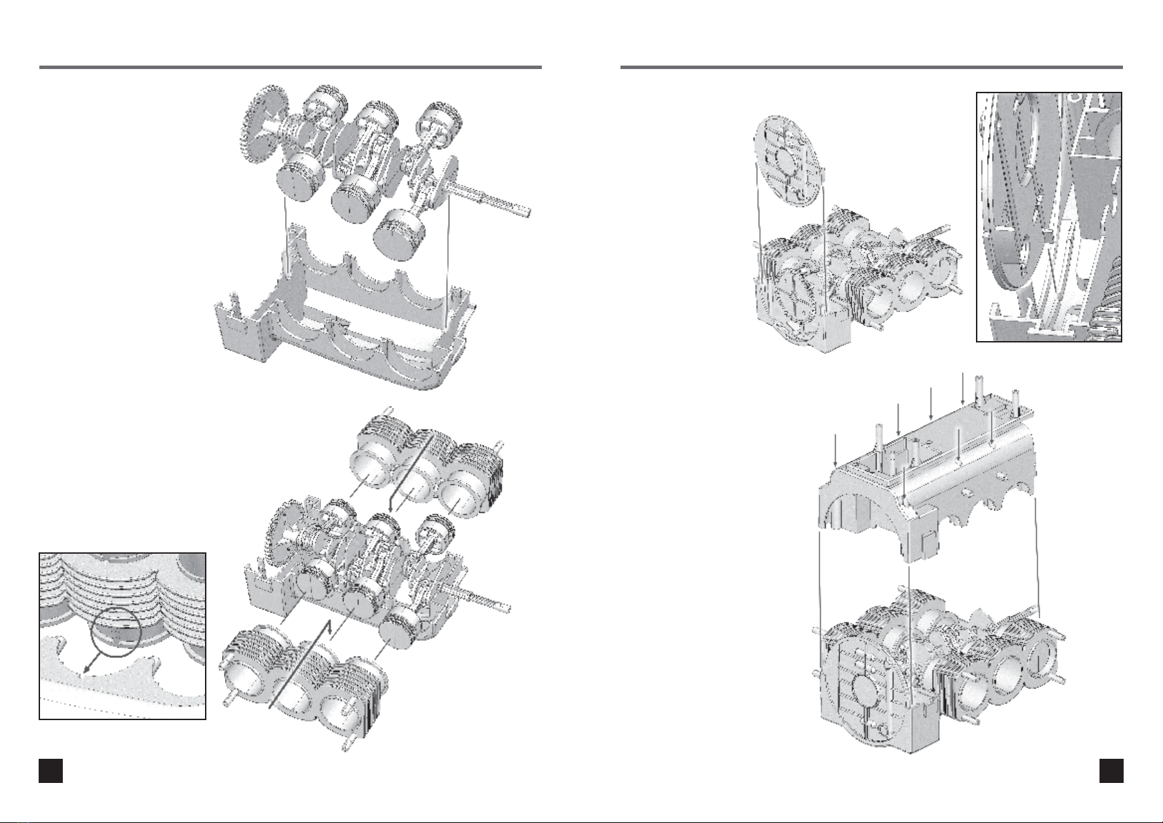
Step 1. Pistons.....................................................15
Step 2. Crankshaft................................................15
Step 3. Crankshaft drive gear................................15
Step 4. Crankshaft assembly ................................16
Step 5. Cylinder barrels........................................16
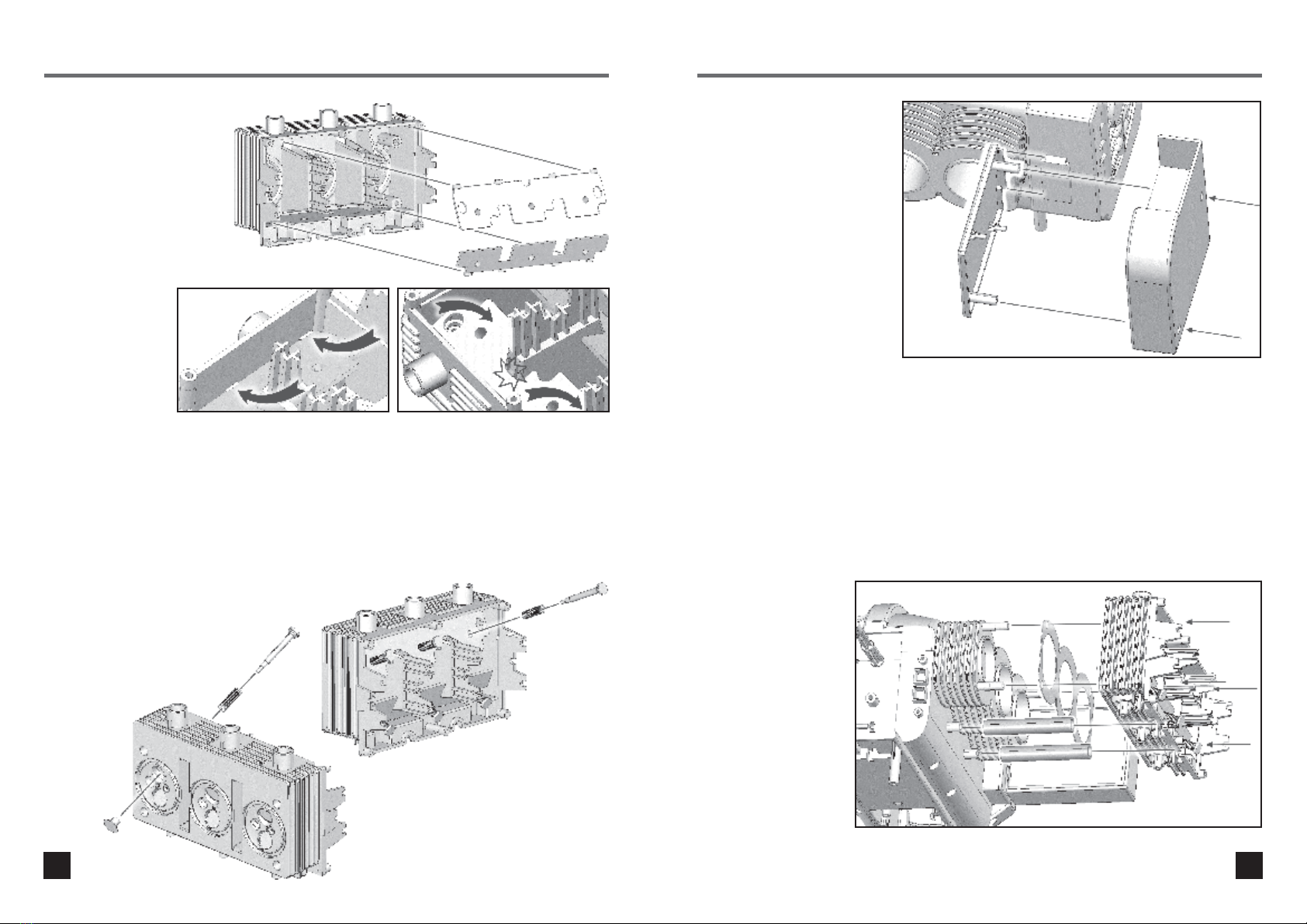
Step 6. Crankcase rear .........................................17
Step 7. Crankcase assembly.................................17
Step 8. Valve guides ............................................18
Step 9. Valve assembly........................................18
Step 10. Oil cooler...............................................19
Step 11. Cylinder head – right side ......................19
Step 12. Camshaft tunnel – right rear ...................20
Step 13. Cam and rocker shafts – right side .........20
Step 14. Camshaft assembly – right side..............21
Step 15. Rocker shaft assembly – right side .........22
Step 16. Cylinder head – left side ........................23
Step 17. Timing pin .............................................24
Step 18. Crankshaft sprocket................................24
Step 19. Valve timing tool ....................................25
Step 20. Cam belt – left side................................25
Step 21. Cam belt cover – left side ......................26
Step 22. Distributor drive gears............................26
Step 23. Cam drive sprocket – right side..............27
Step 24. Cam belt – right side..............................27
Step 25. Cam belt cover – right side ....................28
Step 26. Distributor..............................................28
Step 27. Engine front ...........................................29
Step 28 Crankshaft pulley wheel...........................29
Step 29. Drive motor............................................30
Step 30. Cylinder head covers..............................30
Step 31. Exhaust manifolds ..................................31
Step 32. Exhaust pipes.........................................31
Step 33. Exhaust muffler ......................................32
Step 34. Base - battery installation .......................34
Step 35. Base label..............................................35
Step 36. Base ......................................................36
Step 37. Cooling fan assembly.............................34
Step 38. Cooling fan installation...........................34
Step 39. Spark plugs............................................35
Step 40. Carburettors...........................................36
Step 41. Operation...............................................36
HOW AN ENGINE WORKS.................................37
PE01 Porsche Flat-Six Boxer Engine
© Franzis
All rights reserved. No part of this
publication may be reproduced, stored in a
retrieval system or transmitted, in any form
or by any means, electronic, mechanical,
photocopying, recording or otherwise,
without prior permission in writing from the
publisher.
Printed in China
Please retain the information in
this manual for future reference.
This device complies with Part 15 of the FCC Rules. Operation is subject to
the following two conditions:
(1) this device may not cause harmful interference
(2) this device must accept any interference received,
including interference that may cause undesired operation.
Caution: Changes or modifications not expressly approved by the party responsible
for compliance could void the user’s authority to operate the equipment.
Note: This equipment has been tested and found to comply with the limits for a Class
B digital device, pursuant to part 15 of the FCC Rules. These limits are designed to
provide reasonable protection against harmful interference in a residential
installation. This equipment generates, uses and can radiate radio frequency energy
and, if not installed and used in accordance with the instructions, may cause harmful
interference to radio communications. However, there is no guarantee that
interference will not occur in a particular installation. If this equipment does cause
harmful interference to radio or television reception, which can be determined by
turning the equipment off and on, the user is encouraged to try to correct the
interference by one or more of the following measures:
- Reorient or relocate the receiving antenna.
- Increase the separation between the equipment and receiver.
- Connect the equipment into an outlet on a circuit different from that to which
the receiver is connected.
- Consult the dealer or an experienced radio/TV technician for help.
32
Flat-Six Boxer Engine
Build your own working, classic Porsche 911 flat-six engine model!
Contents
PORSCHE 911

The car that was to become the Porsche 911 was first unveiled at
the 1963 Frankfurt motor show, intended as a larger, more
comfortable, successor to the legendary 356. As well as a new
chassis and suspension, a completely new, six cylinder, overhead
cam boxer engine was designed (called the Type 901), to replace
the four cylinder, overhead valve unit used in the 356. Design of
the new engine was led by Hans Mezger, a German automotive
engine who became a key part of Porsche’s development
programme for 35 years.
The primary reason for using the new 6-cylinder engine was to
utilise the inherent smoothness offered by the boxer configuration.
Because it consisted of three pairs of pistons moving backwards
and forwards in opposite directions, with each pair spaced at 120
degrees of crankshaft rotation, the design minimised first and
second order vibrations (vibrations that occur once and twice per
engine revolution). In addition, the short length of the engine, low
centre of gravity, and effectiveness of air cooling made it ideal for
the rear-engine 911.
To meet the high bending stresses at very high revolutions, the
forged crankshaft was supported with eight main bearings.
The crankcase was split vertically, and like all of the major
components, was made from aluminium (even the cooling fins of
the cylinders were aluminium, with cast iron sleeves inside them).
Each row of three cylinders had an overhead camshaft, these
being driven by a duplex chain running around intermediate gears
on a layshaft (itself gear driven from the crankshaft). Accurate
valve timing and smooth operation were achieved by using a
hydraulic cam chain tensioning wheel and rubber guide ramps.
The valves were arranged in a V-shape, which allowed the use of a
hemispherical combustion chamber with a small, smooth and
heat-absorbing surface. Initial versions of the engine used Solex
overflow-type carburettors, and although these had the benefit of
being relatively insensitive to forces caused by hard cornering,
problems with these, including a flat spot at low engine speeds,
led to them being changed for Weber carburettors in 1966.
INTRODUCTION
4 5
An 11 bladed axial fan,
with the alternator inside it,
was mounted on top of the
engine to improve cooling
by helping to ensure the
air was more evenly
distributed to both sets of
cylinders.
In its original form (Type
901/01), the engine had a
capacity of 1,991 cubic
centimetres, with a
cylinder bore of 80 mm
and a stroke of 66 mm.
Power output was 130 hp (96 kW) at 6,100 rpm. Subsequent
developments led to the 901/02, 901/03 and other versions,
each having different specifications depending on the intended
use (sports, touring etc). The Carrera six engine (Type 906) was
developed simultaneously to the Type 901, the main differences
being the use of twin spark plugs per cylinder,
higher-compression pistons, and the use of lighter weight
(magnesium and titanium) components. A major change came
in 1970, with the capacity of the engine being increased to
2,200 cubic centimetres (2.2 litres) by increasing the bore to 84
mm. The original engine configuration was still being used until
1972, when it was superseded by the even larger 2,341 cubic
centimetre engine.
The model in this kit is intended as representation of the Type
901 engine used in the early 911. Although it lacks the fine
details of the real engine, it includes a realistic crankshaft, a
working cooling fan, and accurate valve and ignition timing.
Even the distributor works correctly, being driven from the
crankshaft using bevel gears, with its red colour closely
matched to the real thing.
An early Porsche 911 engine, with cut-away sections to show the internal
components. The engine shown is part of the Porsche museum collection
in Stuttgart.

No. Description Qty
1 Connecting rod 6
2 Piston half 12
Cams (labelled A – F) 6
4 Bearing cap 6
5 Rocker arm 6
6 Timing tool 1
7 Valve stem 6
9 Valves 12
10 Crankshaft sprocket A 1
11 Crankshaft sprocket B 1
12 Camshaft sprocket 2
13 Gudgeon (piston) pin 6
15 Carburettor outer 2
16 Carburettor inner 2
19 Exhaust muffler upper 1
20 Exhaust muffler lower 1
21 Exhaust pipe left upper 1
22 Exhaust pipe left lower 1
23 Exhaust pipe right upper 1
24 Exhaust pipe right lower 1
25 Crankshaft pulley 1
26 Fan pulley 1
27 Oil return pipes 4
28 Exhaust manifold left upper 1
29 Exhaust manifold left lower 1
30 Exhaust manifold right upper 1
31 Exhaust manifold right lower 1
32 Oil cooler outer 1
33 Oil cooler inner 1
34 Fan housing 1
37 Idler pulley 2
41 Crankshaft 1
42 Cooling fan 1
No. Description Qty
47 Crankcase upper 1
48 Crankcase lower 1
49 Cylinder barrels 2
50 Cylinder head left 1
51 Cylinder head right 1
52 Upper cylinder head left 1
53 Upper cylinder head right 1
54 Large cylinder head plate 2
55 Small cylinder head plate 2
56 Crankcase rear 1
57 Cylinder head plate upper 2
58 Cylinder head plate lower 2
59 Cam belt tunnel left inner 1
60 Cam belt tunnel right inner 1
61 Cam belt tunnel left outer 1
62 Cam belt tunnel right outer 1
63 Cam belt tunnel middle 1
67 Drive gear 1
68 Crankshaft gear 1
69 Distributor gear 1
Cam timing belt 2
72 Spark plug lead mounting clip 1
74 Distributor bushing 1
75 Crankshaft gear B 1
76 Crankshaft gear C 1
77 Timing alignment pin 2
78 Fan housing rear cover 1
Valve spring 12
Cam shaft (140 mm) 2
Rocker shaft (118 mm) 4
Metal shaft (37 mm) 1
Head gasket 2
Base 1
Distributor/spark plug assembly 1
Label 1
References to the left or right side of the engine mean the left or right side when
viewed from the fan end. Cylinders 1-3 are on the left side of the engine and
cylinders 4-6 are on the right.
Identify the various parts by looking at the list of components and the
corresponding illustrations. Use a sharp knife to trim any excess plastic from the
components after they have been removed from their carrier frames.
Take care not to over-tighten the screws as this may permanently damage the
plastic.
- Non-rechargeable batteries are not to be recharged.
- Rechargeable batteries are only to be charged under adult supervision.
- Rechargeable batteries are to be removed from the toy before being charged.
- Do not mix old and new batteries.
- Do not mix alkaline, standard (carbon-zinc), or rechargeable (nickel-cadmium)
batteries.
- Batteries are to be inserted with the correct polarity.
- Exhausted batteries are to be removed from the toy.
- The supply terminals are not to be shorted-circuited.
NOTES AND ADVICE PARTS LIST
6 7

PARTS LIST PARTS LIST
8 9

PARTS LIST PARTS LIST
10 11

19 Muffler upper
20 Muffler lower
25 Crankshaft
pulley
34 Fan
housing
42 Cooling
fan
47 Crankcase upper
48 Crankcase lower
49 Cylinder barrels
37 Idler
pulley
37 mm
shaft
41 Crankshaft
26 Fan pulley
27 Oil return pipes
50 & 51
Cylinder heads
PARTS LIST PARTS LIST
12 13

67 Drive gear
68 Crankshaft
gear
69 Distributor
gear
76 Crankshaft
gear C
Distributor
bush
75 Crankshaft
gear B
Base
Distributor and
plugs
Motor assembly
Rocker and cam shafts
Valve spring
Fan belt
Head gasket
Timing belts
78 Fan
housing
rear cover
52 & 53 Upper cylinder head
PARTS LIST ASSEMBLING THE ENGINE
14 15
Step 1. Pistons
Push a gudgeon (piston) pin (13) through the
small end of a connecting rod (1). Push two
halves of a piston (2) together over the pin and
press together firmly.
Repeat for the other five piston/rod assemblies.
Step 2. Crankshaft
The six connecting rods attach to the
crankshaft (41) in the positions shown.
In each case, place the connecting rod over the
crankshaft, fit a bearing cap (4) and secure with
two screws.
Check that the piston/connecting rod
assemblies rotate freely around the crankshaft.
Step 3. Crankshaft
drive gear
Fit the crankshaft drive gear (68)
to the end of the crankshaft.

ASSEMBLING THE ENGINE ASSEMBLING THE ENGINE
16 17
Step 6. Crankcase rear
Slide the crankcase rear
(56) in to the upper
crankcase. There is a
rib in the plate that fits
into a corresponding
slot in the upper
crankcase - refer to
the inset image (the
crankshaft and drive
gear have been
removed for clarity).
Step 7. Crankcase assembly
Fit the lower crankcase (48)
to the upper crankcase and
secure with seven screws.
Step 4. Crankshaft
assembly
Place the upper crankcase
(47) upside down on a table.
Hold the piston/crankshaft assembly,
and lower it on to the crankcase.
Step 5. Cylinder barrels
Attach the cylinder barrels (49) to the upper
crankcase. Carefully slide the pistons into each
set of barrels and then lower the barrels into the
crankcase. Ensure the barrels are the right
way up - note that the barrel for the
middle piston has a rib that fits into
a corresponding slot in the upper
crankcase.

ASSEMBLING THE ENGINE ASSEMBLING THE ENGINE
18 19
Step 10. Oil cooler
The oil cooler must be fitted at
this time. This is in two parts
(32 & 33), and should be
assembled so that the parts
clamp to the T-shaped
moulding on the side of the
crankcase. Hold the smaller
inner part (33) in place, then fit
the larger outer part of the
cooler (32) to this and secure
with two screws.
Step 11. Cylinder head –
right side
Place a paper cylinder head gasket over the
right hand cylinder barrels. Fit two oil return
pipes (27) to the moulded lugs on the side of
the crankcase, then fit the right cylinder head
(51) and secure with four screws.
Repeat for the other (left)
side of the engine, using
the other gasket, two oil
return pipes, and the left
cylinder head (50).
Step 8. Valve guides
Fit two valve guide plates to
each of the lower cylinder
heads. Note that each head
uses one narrow plate (55)
and one wide plate (54).
Each plate has three round
studs that face downwards
into the head. First fit the
tabs on the outside of
each plate into the
corresponding holes
in the side of the
head, then push the
plates down firmly
so they clip into
position (circled).
Step 9. Valve assembly
For each cylinder head, you will need six valves (9),
valve stems (7) and valve springs. Fit to the head as
shown. First slide a spring over a valve stem, and
insert into one of the six holes in the valve guide plates.
Gently compress the spring until the end of the stem
sticks out of the bottom of the head. Carefully push the
valve on to the stem. Note that the end of the valve has
a step – push the valve until it touches the edge of the
step. DO NOT force the valve – these parts are
delicate.

ASSEMBLING THE ENGINE ASSEMBLING THE ENGINE
20 21
Step 13. continued
Slide three rocker arms (5) on to each
of the two rocker shafts, checking
that they move freely.
Note the relative position of the inlet (top)
and exhaust rockers (bottom).
Step 14. Camshaft assembly –
right side
Place the camshaft assembly in position on the
cylinder head. This is easiest if the engine is
held on its side between your legs, with the
cylinder head horizontal. Ensure that the cams
are separated so that each sits between the
bearing surfaces in the head.
Step 12. Camshaft
tunnel – right rear
Attach the rear part of the right
hand camshaft tunnel (60) to
the crankcase and secure with
two screws.
Step 13. Cam and rocker
shafts – right side
Assemble the camshaft for the right side of
the engine. Slide cams D, E, and F on to a
camshaft, IN THIS ORDER.
Note that the hole in each cam has a flat
surface, which ensures that each one is
correctly positioned on the shaft. Also note
that there is a rib at one end of each cam.
IMPORTANT! To ensure correct valve timing,
the cams must all be fitted with the rib
pointing to the REAR of the engine (direction
of arrow in diagram below).
Fit the sprocket to the end of the camshaft –
the hole in this also has a flat surface to
ensure it is correctly positioned.

ASSEMBLING THE ENGINE ASSEMBLING THE ENGINE
22 23
Step 16. Cylinder head –
left side
Repeat steps 11 to 14 for the left hand side of
the engine. Note the position of cams A, B and
C, making sure the ribs on each point towards
the rear of the engine.
Step 15. Rocker shaft
assembly – right side
Place the rocker shaft assemblies for the inlet
and exhaust valves on to the cylinder head
(refer to the inset picture for guidance). Use
your fingers to separate the rockers so that
each sits between the bearings that hold the
shaft. The ends of each rocker shaft should be
level with the end of the cylinder head.
Place the cylinder head cover (53) in position.
Note the correct orientation - the two tubes
moulded into the bottom edge should be
inserted into the ends of the oil return pipes.
Secure with six screws.

ASSEMBLING THE ENGINE ASSEMBLING THE ENGINE
24 25
Step 19. Valve timing tool
Fit the valve timing tool (6) to
the left hand side of the engine.
There are two pins at one end
that fit into the holes in the
sprocket beneath the
crankshaft, and three at the
other end that fit into holes in
the camshaft sprocket.
Step 20. Cam belt – left side
Remove the timing alignment
pin as shown (but do not
remove the one in the lower
sprocket). Place one of the
cam timing belts in position
over the cam and drive
sprockets. Install the idler
pulley (37), making sure the
cam belt goes up and
over this.
Step 17. Timing pin
In order to accurately set the valve and ignition
timing, the crankshaft must be locked into
position. Note that the pistons in cylinders
1 and 4 must be at Top Dead
Centre (TDC). Insert a timing
alignment pin (77) through the
holes in the crankcase and
crankshaft counterweight.
Insert the metal shaft for the
cam chain sprocket into the
crankcase.
Step 18. Crankshaft sprocket
Slide the crankshaft gear B (75) on to the end
of the crankshaft. Note that there is a slot in the
inside surface of the sprocket that engages
with a rib on the crankshaft.
Fit the crankshaft sprocket A
(10) to the metal shaft. Note
that the shaft has a flat surface
on one side that matches a flat
surface on the inside of the
sprocket. IMPORTANT! There
is a hole on one side of the
sprocket through which the
second timing alignment pin
(77) must be inserted to fit into
a hole in the crankcase. This
ensures that the sprocket is
correctly aligned. You may
need to reposition the sprocket
to allow the pin to be inserted.

ASSEMBLING THE ENGINE ASSEMBLING THE ENGINE
26 27
Step 23. Cam drive sprocket –
right side
Fit the crankshaft sprocket B (11) to the metal
pin, followed by the valve timing tool.
Step 24. Cam belt – right side
Install the second cam belt and idler pulley.
Step 21. Cam belt cover –
left side
Remove the valve timing tool,
and the timing alignment pin
from the lower sprocket.
Fit the cam belt tunnel cover
(61) and secure with three
screws.
Step 22. Distributor drive gears
Install the distributor drive bevel gears. Fit the
smaller crankshaft gear C (76) first - it has a slot
that engages with the rib on the crankshaft.
When fitting the larger gear (69), note the round
groove in one side. To achieve correct ignition
timing, this gear MUST be installed with the flat
section facing downwards as shown. Slide a
timing pin under the gear and into the bracket
in the front of the crankcase to ensure the gear
is correctly positioned.

ASSEMBLING THE ENGINE ASSEMBLING THE ENGINE
28 29
Step 27. Engine front
Attach the engine cover plate
and secure with three screws.
Step 28 Crankshaft
pulley wheel
Fit the pulley to the end of the
crankshaft and secure with
a screw.
Step 25. Cam belt cover –
right side
Remove the valve timing tool
and the bevel gear locking pin.
Place the right hand cam belt
cover in position and secure
with three screws.
Step 26. Distributor
Fit the distributor bush (74) to the end of the
shaft and secure with a screw. One end of the
bush has a recess for the screw; this must face
outwards, as shown.
Fit the distributor – it is a friction fit in the
crankcase. The flat surface on the distributor
shaft and bush match the flat surfaces
of the crankcase and bevel
gear. The bevel drive gear for
the distributor MUST be in the
correct position in order for the
distributor shaft to be fully
inserted.

ASSEMBLING THE ENGINE ASSEMBLING THE ENGINE
30 31
Step 31. Exhaust manifolds
Each exhaust manifold is made up from two
parts. Assemble the upper (30) and lower
(31) halves of the right manifold and secure
with four screws. Fit the assembled manifold
to the underside of the cylinder head and
secure with three screws. Repeat for the left
hand side, using parts (28) and (29).
Step 32. Exhaust pipes
Each set of exhaust pipes is also made up from
two parts. Assemble the upper (23) and lower
(24) halves of the right exhaust and secure with
one screw. Fit the assembled exhaust to the
manifold and secure with three screws. Repeat
for the left hand side, using parts (21) and (22).
Step 29. Drive motor
Fit the drive gear (67) to the
motor shaft. One side of the
gear is recessed; make sure
the recess is facing outwards,
and secure using one of the
metal washers and a screw.
Insert the motor/gearbox
assembly into the hole in the
lower part of the crankcase
and secure with three screws.
Step 30. Cylinder head covers
Attach the upper (57) and lower cylinder (58)
head covers, securing each with six screws.

ASSEMBLING THE ENGINE ASSEMBLING THE ENGINE
32 33
Step 34. Base - battery
installation
Remove the battery compartment cover. Insert
3 x AA batteries in the compartment, taking
care to ensure that the battery markings
(polarity) match the markings in the
compartment. Replace the battery cover.
Step 33. Exhaust muffler
Assemble the two halves of the exhaust muffler
(19 & 20) and secure with four screws.
Slide the muffler over the ends of the exhaust
pipes. The muffler is secured to each exhaust
pipe with a single screw, and to the crankcase
with two screws.
Step 35. Base label
Remove the foil label from the backing paper
and place in position on the base.
Step 36. Base
Attach the base to the bottom of the crankcase
and secure with four screws.

ASSEMBLING THE ENGINE ASSEMBLING THE ENGINE
34 35
Step 39. Spark
plugs
Insert the spark plugs into
the holes in the upper part of
the cylinder heads. Carefully
note the markings on the top
of the distributor cap; follow
the wire that exits from hole
#1 and insert it into cylinder
number 1 as shown. Repeat
for wires/cylinders 2, 3, 4, 5
and 6.
Use the clip (72) provided to
secure the wires for cylinders
4, 5 and 6 so they are routed
neatly over the cooling fan.
Step 37. Cooling fan
assembly
Assemble the cooling fan components
as shown. Attach the rear cover (78) to
the fan housing (34) first, and secure with
two screws. Slide the fan (42) over the shaft,
followed by the fan pulley (26). Secure the
pulley to the fan using a screw and washer.
Check that the fan spins freely; if necessary,
loosen the screw slightly.
Step 38. Cooling fan
installation
Insert the clip on the bottom of
the cooling fan assembly into
the slot in the crankcase.
Fit the fan drive belt – this fits
over the crankcase pulley
and the fan pulley.

ASSEMBLING THE ENGINE
36 37
Step 40. Carburettors
Each set of carburettors is in
two halves (15 & 16). Fit each
pair together and secure with
four screws. Place each in
position over the three inlet
pipes on the top of the cylinder
heads.
Step 41. Operation
Insert the two electrical plugs into the base -
they are two different sizes, and will only fit one
way.
Press the on/off button on the
base to begin operating the
engine. It will continue to run
for 30 seconds and then stop
automatically. Press the on/off
button while the engine
is running to stop it
before the end of the
30 second cycle. Pressing
the button again will start
another 30 second cycle.
HOW AN ENGINE WORKS
Basic Principles
To explain how a full-size car engine works, we’ll use a simplified version of a real engine -
our model engine in fact. You can switch on your finished model as you read this
explanation and it will help you to understand how a real engine works.
An engine crankshaft is described as such because it is a ‘cranked’ shaft – the shaft has
offset sections, to which the six piston/connecting rod assemblies are connected. In the
model, as the crankshaft turns (driven by the electric motor), the cranked sections move
around the centreline of the crankshaft, and convert the rotation to the reciprocating (up
and down) movement of the pistons. In a real engine, it is the movement of the pistons
(driven by the burning of fuel in the cylinders) that causes the crankshaft to rotate.
The engine’s crankshaft drives the transmission, which includes various different
components connected together whose job it is to drive the car’s wheels, making the
car move.
Now let’s look at how the engine works in more detail. We’ll look at just one cylinder of the
engine. A cylinder is the hollow cylinder inside the engine in which one piston moves up and
down. The piston has seals, called piston rings, around its edge, which aren’t shown on our
model and these seals stop gases passing round the sides of the piston. Our model has
six cylinders.
When you turn the engine to start the car, the starter (a powerful electric motor, powered by
the car’s battery) turns the crankshaft, moving the pistons up and down.
As a piston moves down from its highest position inside the cylinder (called ‘Top Dead
Centre’ or ‘TDC’), a mixture of fuel and air is sucked into the space inside the cylinder
above the piston. This is called the intake stroke.
The starter continues to turn the crankshaft and, as the piston moves back up towards the
top of its cylinder, the fuel/air mixture is compressed (squashed) in the space above the
piston. This is called the compression stroke.
As the piston reaches its highest point, a spark plug creates a spark above the piston and
this spark ignites the fuel/air mixture, causing a small controlled explosion above the piston.
The explosion pushes the piston downwards and this is called the power stroke.
Once the piston has reached its lowest point, it starts to move back up its cylinder, pushing
the burnt gases out through the top of the cylinder. This is called the exhaust stroke.
So, the engine has four strokes; intake, compression, power and exhaust, or ‘suck’,
‘squeeze’, ‘bang’ and ‘blow’ to make it simpler. These four strokes make up the
4-stoke cycle.
The fuel/air mixture flows into the space above the piston, called the combustion chamber.
The mixture flows in through a small hole which is opened and closed by the inlet valve.
The burnt gas flows out of the cylinder through another hole which is opened and closed by
the exhaust valve. The valves are normally held closed by springs, but as the engine turns the
valves are pushed open in the correct order by the rocker arms, which are moved by the
camshaft. The rocker arm pushes the valve down against its spring and, as the rocker moves
up, the spring pushes the valve closed.

HOW AN ENGINE WORKS HOW AN ENGINE WORKS
38 39
Basic Principles
To explain how a full-size car engine works, we’ll use a simplified version of a real engine -
our model engine in fact. You can switch on your finished model as you read this
explanation and it will help you to understand how a real engine works.
An engine crankshaft is described as such because it is a ‘cranked’ shaft – the shaft has
offset sections, to which the six piston/connecting rod assemblies are connected. In the
model, as the crankshaft turns (driven by the electric motor), the cranked sections move
around the centreline of the crankshaft, and convert the rotation to the reciprocating (up
and down) movement of the pistons. In a real engine, it is the movement of the pistons
(driven by the burning of fuel in the cylinders) that causes the crankshaft to rotate.
The engine’s crankshaft drives the transmission, which includes various different
components connected together whose job it is to drive the car’s wheels, making the
car move.
Now let’s look at how the engine works in more detail. We’ll look at just one cylinder of the
engine. A cylinder is the hollow cylinder inside the engine in which one piston moves up and
down. The piston has seals, called piston rings, around its edge, which aren’t shown on our
model and these seals stop gases passing round the sides of the piston. Our model has
six cylinders.
When you turn the engine to start the car, the starter (a powerful electric motor, powered by
the car’s battery) turns the crankshaft, moving the pistons up and down.
As a piston moves down from its highest position inside the cylinder (called ‘Top Dead
Centre’ or ‘TDC’), a mixture of fuel and air is sucked into the space inside the cylinder
above the piston. This is called the intake stroke.
The starter continues to turn the crankshaft and, as the piston moves back up towards the
top of its cylinder, the fuel/air mixture is compressed (squashed) in the space above the
piston. This is called the compression stroke.
As the piston reaches its highest point, a spark plug creates a spark above the piston and
this spark ignites the fuel/air mixture, causing a small controlled explosion above the piston.
The explosion pushes the piston downwards and this is called the power stroke.
Once the piston has reached its lowest point, it starts to move back up its cylinder, pushing
the burnt gases out through the top of the cylinder. This is called the exhaust stroke.
So, the engine has four strokes; intake, compression, power and exhaust, or ‘suck’,
‘squeeze’, ‘bang’ and ‘blow’ to make it simpler. These four strokes make up the
4-stoke cycle.
The fuel/air mixture flows into the space above the piston, called the combustion chamber.
The mixture flows in through a small hole which is opened and closed by the inlet valve.
The burnt gas flows out of the cylinder through another hole which is opened and closed by
the exhaust valve. The valves are normally held closed by springs, but as the engine turns the
valves are pushed open in the correct order by the rocker arms, which are moved by the
camshaft. The rocker arm pushes the valve down against its spring and, as the rocker moves
up, the spring pushes the valve closed.
The 1st stroke (intake)
The piston starts off at the top of the
cylinder. The exhaust valve is closed and
the inlet valve is open. As the crankshaft
turns and the piston moves down inside the
cylinder, fuel/air mixture is sucked in
through the inlet valve. When the piston
reaches its lowest point inside the cylinder,
the cylinder is filled with fuel/air mixture and
the inlet valve closes. This is the end of the
intake stroke.
The 2nd stroke (Compression)
At the start of the compression stroke, the
piston is at its lowest point inside the
cylinder and the inlet and exhaust valves are
closed. The crankshaft continues turning
and the piston moves upwards. As the
piston moves upwards it squeezes
(compresses) the fuel/air mixture and this
increases the temperature of the mixture
very quickly. When the piston reaches its
highest point the mixture is fully compressed
and this is the end of the compression
stroke.
4-stroke cycle
Inlet valve open Valves closed
Piston rises
compressing
fuel/air
mixture
Exhaust
valve
closed Inlet port
Piston moves
down sucking
in fuel/air
mixture
Connecting
rod
Crankshaft
rotation
The 4th stroke (Exhaust)
As the piston starts to move up inside the
cylinder again, the exhaust valve opens to
allow the burnt (exhaust) gas to escape
from the cylinder and as the piston moves
up the cylinder it pushes the gas out
through the exhaust valve. As the piston
reaches the top of the cylinder the exhaust
valve closes, the exhaust stroke ends and
the 4-stroke cycle begins again with another
intake stroke.
The 3rd stroke (Power)
The very high pressure and temperature
inside the combustion chamber cause the
fuel/air mixture to break up into very fine
particles, like a mist. These are perfect
conditions for burning a gas. All that’s
needed to start the burning (or ‘combustion’ –
a kind of controlled explosion) is a spark. A
very high electrical voltage supplied to the
spark plug causes a spark to jump across the
gap at the end of the spark plug. This ignites
the fuel/air mixture and starts the combustion.
The force of the controlled explosion and the
expanding gases forces the piston
downwards, which pushes the crankshaft
round. During the power stroke, three things
happen to the fuel/air mixture – it ignites,
combusts (burns) and expands. The
expansion of the gas pushes the piston
down, which transfers power to the
crankshaft. When the piston reaches its
lowest point inside the cylinder this is the end
of the power stroke.
Valves closed
Piston forced
down by
expanding
gases
Exhaust valve open
Piston moves
up forcing
exhaust
gases out of
cylinder
Fuel / air
mixture
ignites
Table of contents
Other Franzis Toy manuals