Techlogix TL-SM3X1-HD User manual

User Manual
TL-SM3X1-HD
3x1 Video Switching System
All Rights Reserved
Version: TL-SM3X1-HD_160925

www.tlnetworx.com
TL-SM3X1-HD User Manual
Preface
Read this user manual carefully before using this product. Pictures shown in this manual
are for reference only; the actual product may vary.
This manual is only for operation instruction only and not for any maintenance or repair.
Trademarks
Product model and logo are trademarked. Any other trademarks mentioned in this
manual are acknowledged as the properties of the trademark owner. No part of this
publication may be copied or reproduced without prior written consent.
FCC Statement
This equipment generates, uses and can radiate radio frequency energy and, if not
installed and used in accordance with the instructions, may cause harmful interference
to radio communications. It has been tested and found to comply with the limits for a
Class A digital device, pursuant to part 15 of the FCC Rules. These limits are designed to
provide reasonable protection against harmful interference in a commercial installation.
Operation of this equipment in a residential area is likely to cause interference, in which
case the user at their own expense will be required to take whatever measures may be
necessary to correct the interference.
Any changes or modifications not expressly approved by the manufacture would void
the user’s authority to operate the equipment.

www.tlnetworx.com
TL-SM3X1-HD User Manual
SAFETY PRECAUTIONS
To insure proper operation, please read all instructions carefully before using the device.
Save this manual for further reference.
l Unpack the equipment carefully and save the original box and packing material for
possible future shipment
l Follow basic safety precautions to reduce the risk of fire, electrical shock and injury
to persons.
l Do not dismantle the housing or modify the module. It may result in electrical shock
or burn.
l Using supplies or parts not meeting the products’ specifications may cause damage,
deterioration or malfunction.
l Refer all servicing to qualified service personnel.
l To prevent fire or shock hazard, do not expose the unit to rain, moisture or install
this product near water.
l Do not remove the housing of the device, as opening or removing housing may
expose you to dangerous voltage or other hazards.
l Install the device in a place with adequate ventilation to avoid damage caused by
overheating.
l Keep the device away from liquids.
l Spillage into the housing may result in fire, electrical shock, or equipment damage. If
an object or liquid falls or spills on to the housing, unplug the device immediately.
l Do not use liquid or aerosol cleaners to clean this unit. Always unplug the power to
the device before cleaning.
l Unplug the power cord when left unused for a long period of time.
l If disposing of the unit, do not burn or mix with general household waste. The device
must be disposed of per local regulations for electronic recycling.

TL-SM3X1-HD User Manual
www.tlnetworx.com
Contents
1. Introduction ..................................................................................................................................... 1
1.1 Introduction to TL-SM3X1-HD ........................................................................................ 1
1.2 Features ................................................................................................................................. 1
1.3 Package List .......................................................................................................................... 2
2. Panel Description ........................................................................................................................... 3
2.1 Front Panel ........................................................................................................................... 3
2.2 Rear Panel ............................................................................................................................. 4
2.3 Example Table Inserts ........................................................................................................ 4
3. System Connection ........................................................................................................................ 6
3.1 Usage Precautions .............................................................................................................. 6
3.2 System Diagram ................................................................................................................... 6
3.3 Connection Procedure ....................................................................................................... 7
4. System Operations ......................................................................................................................... 9
4.1 Front Panel Buttons ............................................................................................................ 9
4.1.1 Manual-switching .................................................................................................... 9
4.1.2 Auto-switching ......................................................................................................... 9
4.2 IR Remote ........................................................................................................................... 10
5. Specification .................................................................................................................................. 11
6. Panel Drawing ............................................................................................................................... 12
7. Troubleshooting & Maintenance .............................................................................................. 13
8. After-sales Service ....................................................................................................................... 14

1
TL-SM3X1-HD User Manual
www.tlnetworx.com
1. Introduction
1.1 Introduction to TL-SM3X1-HD
The TL-SM3X1-HD is a 3x1 video switcher with three HDMI inputs and one HDMI
output. The unit supports HDMI video resolutions up to 4K@30, as well as multichannel
audio.
The TL-SM3X1-HD supports two operating modes: auto-switch mode and manual
switch mode. When in auto-switch mode, the unit will automatically switch to a signal
input as soon as a new source is connected. When the active source is removed, the
unit will select the first source on the lowest numbered input.
In manual switch mode, the TL-SM3X1-HD will switch between connected inputs when
a control command is sent to the unit via IR or through a command sent by compatible
table inserts, or by using buttons on the front panel of the unit.
In addition to controlling the switching of the source inputs, the TL-SM3X1-HD also
controls a display connected via an HDMI cable via CEC commands. This allows for
automatic power on/off commands to be transmitted from the unit (as well as
connected table inserts) to the display, thereby providing a complete room connectivity
and control solution.
1.2 Features
l Three HDMI inputs & one HDMI output
l HDMI video resolution up to 4K@30Hz 4:4:4
l HDMI 1.4 & HDCP 1.4 compliant
l MHL support on HDMI input channel 1
l IR remote control & front panel control
l Integration with TechLogix table inserts for signal pass-through & remote control
l Micro USB firmware port
l EDID pass-through
l CEC pass-through with display control
l Hot-plug support

2
TL-SM3X1-HD User Manual
www.tlnetworx.com
1.3 Package List
l 1 x TL-SM3X1-HD switcher
l 1 x IR Remote
l 1 x 3.5mm audio cable (3m) (optional)
l 1 x Power Adapter (DC 12V 1A)
l 2 x Mounting rails (with 8 screws)
l 4 x Rubber feet
l 1 x User Manual
3
TL-SM3X1-HD User Manual
www.tlnetworx.com
2. Panel Description
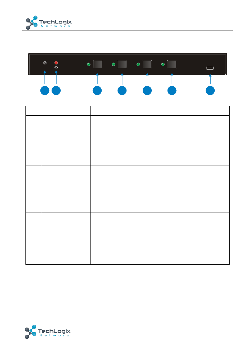
2.1 Front Panel
No.
Name
Description
①
Built-in IR
Receiver
Receives IR control signals sent from a remote control
②
Power LED
Illuminates red when properly powered on
③
HDMI 1 input
Selector &
Activity LED
Button: Provides manual switching to HDMI channel 1
LED: illuminates green when HDMI channel 1 is selected
④
HDMI 2 input
Selector &
Activity LED
Button: Provides manual switching to HDMI channel 2
LED: illuminates green when HDMI channel 2 is selected
⑤
HDMI 3 input
Selector &
Activity LED
Button: Provides manual switching to HDMI channel 3
LED: illuminates green when HDMI channel 3 is selected
⑥
Auto-Switching
Mode Selector &
Activity LED
Button: Turns on/off auto-switching
LED: illuminates green when auto-switching mode is
selected
Note: During auto-switching mode, front panel switching
is disabled
⑦
Firmware
Micro USB port used for firmware update
Note: Pictures shown in this manual are for reference only; actual product may vary.
IR
FIRMWARE
HD MI 1 HD MI 2 HD MI 3 AUTO
1234567

4
TL-SM3X1-HD User Manual
www.tlnetworx.com
2.2 Rear Panel
No.
Name
Description
①
HDMI/MHL IN 1
HDMI input port 1
Note: Supports both HDMI and MHL connections
②
HDMI IN 2
HDMI input port 2
③
HDMI IN 3
HDMI input port 3
④
HDMI OUT
HDMI output port
⑤
C1~C3
Dry contact closure control ports (for use with compatible
TechLogix table inserts)
⑥
DC 12V
12V power port
Note: Pictures shown in this manual are for reference only; actual product may vary.
2.3 Example Table Inserts
HDMI/MHL IN 1 HDMI IN 2 HD MI I N 3 HD MI OUT DC12V C1 C2 C3
123456
SHO W ME ON OFF
/
34
12

5
TL-SM3X1-HD User Manual
www.tlnetworx.com
No.
Name
Description
①
SHOW ME
Button: Selects the corresponding input on the TL-
SM3X1-HD
②
ON/OFF
Button: Select to power on/off a connected display
③
HDMI input port
Local table connection for sources
④
HDMI output port
Connection to switcher
Note: HDMI signals are passed from the source device (connected via the HDMI input
port), through the table insert, and to the switcher (connected via the HDMI output port).
6
TL-SM3X1-HD User Manual
www.tlnetworx.com
3. System Connection
3.1 Usage Precautions
1) System should be installed in a clean environment that has a proper temperature and
humidity.
2) All of the power switches, plugs, sockets and power cords should be installed
properly.
3) All devices should be connected before powering on the devices.
4) If mounting the unit, the included mounting hardware must be used.
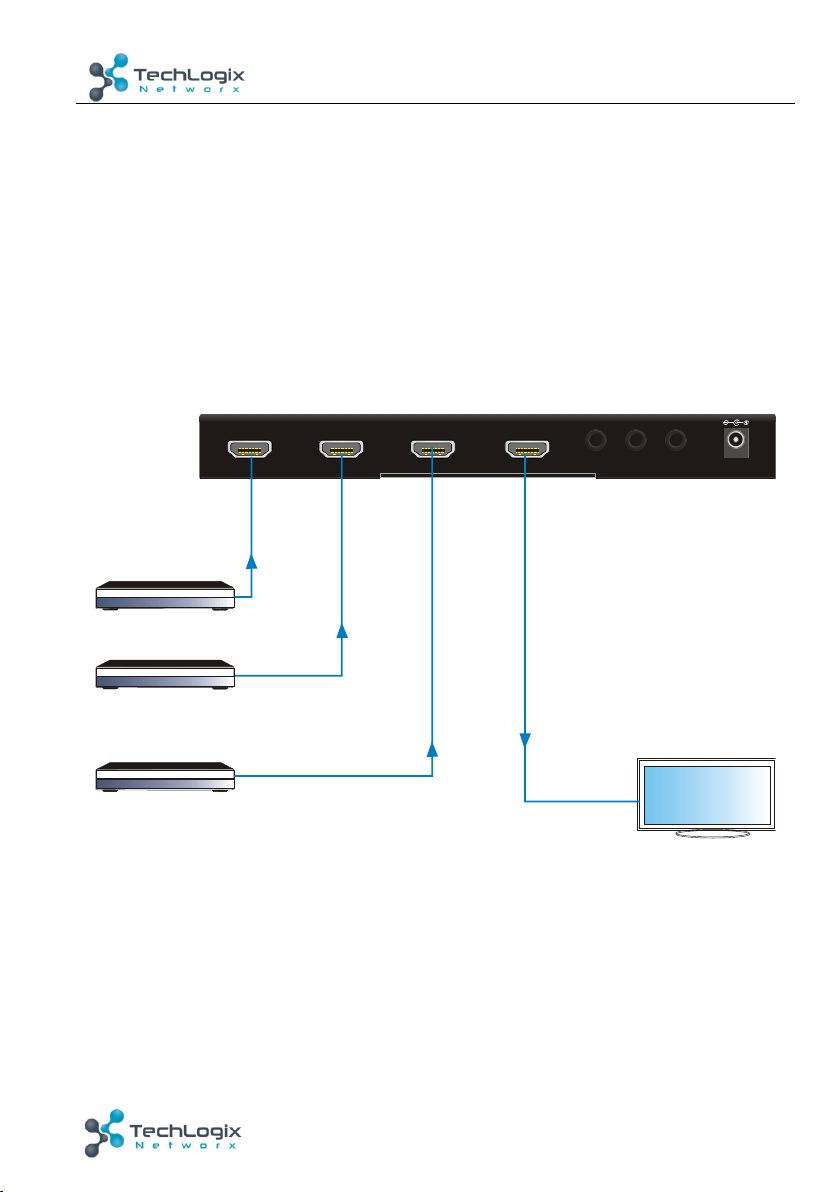
3.2 System Diagram
3-1 Example System Diagram (without table inserts)
HDMI/MHL IN 1 HDMI IN 2 HDMI IN 3 HDMI OUT DC12V C1 C2 C3
Blu ray DVD-
Blu ray DVD-
Blu ray DVD-
HDTV

7
TL-SM3X1-HD User Manual
www.tlnetworx.com
3-2 System Diagram (with table inserts)
3.3 Connection Procedure
1. Verify all components included with the TL-SM3X1-HD are present before
installation.
2. If the TL-SM3X1-HD will be permanently mounted to a surface, attach the
included Mounting rails with the supplied screws.
3. If the TL-SM3X1-HD will be sitting on a shelf, attach the included rubber feet
to the bottom of the unit.
4. Turn off power and disconnect the audio/video equipment by following the
manufacturer’s instructions.
5. Connect HDMI signal cables between the HDMI sources and the HDMI IN 1,
HDMI IN 2 and HDMI IN 3 ports.
Front Panel
SHOW ME ON OFF
/
HDMI Table Plug Module
-
Rear Panel
HD MI /M HL IN 1 HD MI I N 2 HD MI I N 3 HD MI O UT DC 12 V C1 C2 C3
Front Panel
SHOW ME ON OFF
/
HDMI Table Plug Module
-
Rear Panel
Blu ray DVD
-
Front Panel
SHOW ME ON OFF
/
HDMI Table Plug Module
-
Rear Panel
Blu ray DVD
-
HDTV
Blu ray DVD
-
8
TL-SM3X1-HD User Manual
www.tlnetworx.com
6. Connect an HDMI cable between the display and the HDMI OUT port.
7. If the 3x1 video switcher will be controlled via TechLogix table inserts:
1) Separately connect HDMI signal cables between the HDMI sources and
HDMI ports of the table inserts.
2) Separately connect HDMI signal cables between the HDMI ports of table
inserts and the HDMI/MHL IN 1, HDMI IN 2 and HDMI IN 3 ports of the
TL-SM3X1-HD.
3) Separately connect three table inserts to the C1, C2, and C3 ports of the
TL-SM3X1-HD.
8. Connect the included 12VDC power adaptor to the TL-SM3X1-HD.
9. Power on attached audio/video devices.
Important notice:
lDo not attempt to disassemble or alter the TL-SM3X1-HD housing. There are
no user-serviceable parts inside the unit. Doing so will void your warranty.
lTo minimize the possibility of equipment damage from electrostatic discharge
(ESD), all source and destination equipment must be powered off during
installation.
l
Allow proper ventilation to reduce the risk of thermal failure.

9
TL-SM3X1-HD User Manual
www.tlnetworx.com
4. System Operations
4.1 Front Panel Buttons
The front panel buttons may be used for source selection. Video signals support auto-
switching and manual switching (factory default).
4.1.1 Manual-switching
Press HDMI 1, HDMI 2 or HDMI 3 on front panel to select the corresponding input
source.
4.1.2 Auto-switching
Press AUTO to enter into auto-switching mode.
The auto-switching mode abides by the following principles:
Ø New input
When a new signal (or connection) is detected, the TL-SM3X1-HD switches to this
new signal automatically.
Ø Rebooting device
The TL-SM3X1-HD will save the last configuration before losing power. If the last
switching mode is auto-switching, once rebooted, the TL-SM3X1-HD will
automatically enter auto-switching mode, then detect all inputs and memorize their
connection status for future use. If the last displayed signal is still available, the unit
will output the signal. If not, the unit will detect all the input signals with priority
from HDMI 1 to HDMI 3.
Ø Removing signals
Should an active signal be removed, the TL-SM3X1-HD will detect all input signals
with priority from HDMI 1 to HDMI 3. It will transfer the first signal detected to the
display.
10
TL-SM3X1-HD User Manual
www.tlnetworx.com
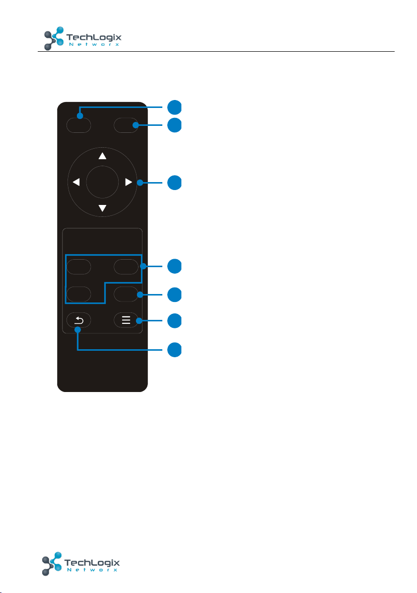
4.2 IR Remote
The built-in IR receiver on the front panel will receive IR control signals sent by a
remote control (included).
① OFF
Powers off the connected display using CEC
commands
② ON
Powers on the connected display using CEC
commands
③ OK: confirm button
Navigation buttons: UP/DOWN/LEFT/
RIGHT allow for resolution selection
④ Input source selection buttons
1=HDMI 1, 2=HDMI 2, 3=HDMI 3
Select video source via pressing corresponding
button
⑤ Auto button
Enter/Exit auto-switching mode
⑥ Menu button
Note: typically not used
⑦ Return button
OK
1 2
AUTO
3
ONOFF 2
3
4
5
6
7
1

11
TL-SM3X1-HD User Manual
www.tlnetworx.com
5. Specification
Input/output
Video Input
1 HDMI/MHL
2 HDMI
Video Input Connector
3 female HDMI
Input Video Signal
HDMI
Video Output
1 HDMI
Video Output Connector
1 female HDMI
Output Video Signal
HDMI
Output Resolution
HDMI output video support HDMI 1.4 & HDCP 1.4;
maximum resolution of 4K@30
Control Part
Control Port
3 Dry Contact (C1~C3)
1 FIRMWARE
Control Connector
3 3.5mm mini jack
1 Micro-USB
Control Buttons
HDMI 1, HDMI 2, HDMI 3, AUTO
General
Temperature
0 ~ +50℃
Humidity
10% ~ 90%
Power Supply
DC12V 1A
Max Power Consumption
2W
Dimension (W*H*D)
201.5mm x 22.0mm x 84.0mm
Weight
246g

12
TL-SM3X1-HD User Manual
www.tlnetworx.com
6. Panel Drawing
HDM I/M HL IN 1 HDM I IN 2 HDM I IN 3 HDM I OUT DC12V C1 C2 C3
3x 1 Vi de o Sw it cher TL-SM3X1-HD
IR
FIRMWARE
HDM I 1 HDM I 2 HD MI 3 AUTO
201.5 mm
84.0 mm
22.0 mm

13
www.tlnetworx.com
TL-SM3X1-HD User Manual
7. Troubleshooting & Maintenance
Problems
Causes
Solutions
Output image with
snowflakes or static
Poor cable quality
Replace the cable
Failing or loose
connection
Check the cable
connection
No output image when
switching
No signal at the input /
output end
Check with oscilloscope or
multi-meter
Failing or loose
connection
Check the cable
connection
Failure of the unit
Contact TechLogix
technical support
POWER indicator doesn’t
illuminate or lack of unit
response
Power supply/cable
failure
Check the power supply
connection
Static becomes stronger
when connecting the
video connectors
Bad grounding
Check unit and power
supply ground connection
If your problem persists after following the above troubleshooting steps, please contact
your authorized reseller or TechLogix technical support.

14
www.tlnetworx.com
TL-SM3X1-HD User Manual
8. After-sales Service
1) Product Limited Warranty: We warrant that our products will be free from defects
in materials and workmanship for three years.
2) Warranty coverage may be voided when:
l The warranty period has expired
l The factory applied serial number has been altered or removed from the product
l There is damage, deterioration or malfunction caused by:
l Atypical wear and tear
l Use of supplies or parts not meeting the specifications
l No certificate or invoice as the proof of warranty
l Damage caused by force majeure
l Non-authorized service
3) Technical Support: When contacting TechLogix support, please have the following
information available:
l Product part number
l Installation and sale date
l Detailed failure information
Table of contents
Other Techlogix Switch manuals


Popular Switch manuals by other brands


Honeywell
Honeywell ZW4005 user manual

Weidmüller
Weidmüller Premium Line IE-SW-PL10M Series Hardware installation guide

Enterasys
Enterasys 08H20G4-24 Hardware installation guide

DVIGear
DVIGear DVI-4141 user manual

Oracle
Oracle InfiniBand Switch IS2-46 Service manual

GarrettCom
GarrettCom Magnum PS14P Installation and user manual