www.techly.it
LED LCD TV Fixed Wall Mount
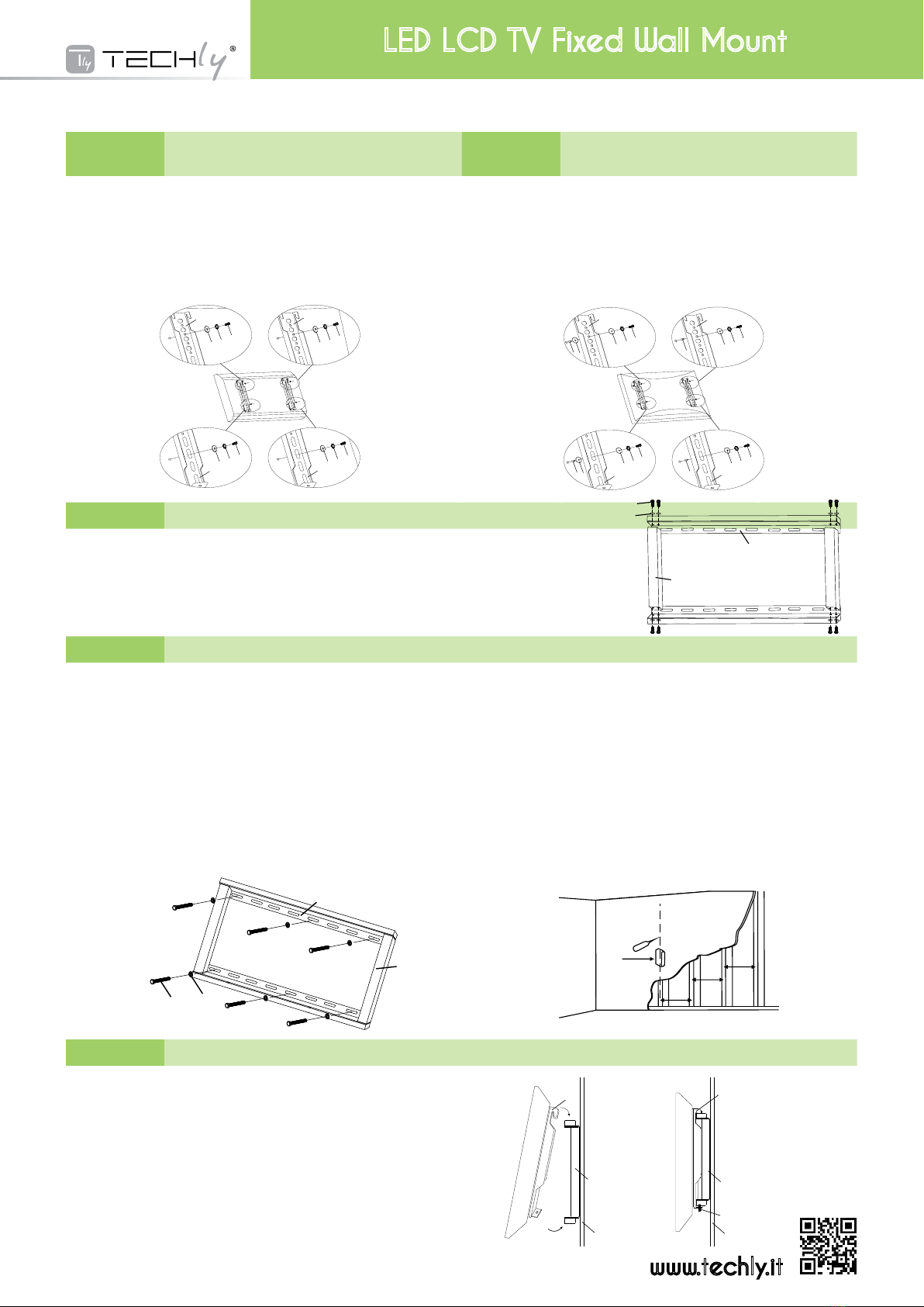
STEP 1A Montaggio della staffa per il monitor a una TV con retro
piatto | Mounting the Monitor Brackets to a TV with Flat
Back STEP 1B Montaggio della staffa per il monitor a una TV con retro
curvo | Mounting the Monitor Brackets to a TV with Curved
Back
Primaditutto,vericateildiametrodelleviti(e,f,g,h)richiestedallavostraTV.
Appenaavetedeterminatoildiametrocorretto,visionateloschemasottoriportato.
Dovetequindiinlarelevitinelretrodellatelevisioneutilizzandolecorretterondelledentellate(m,
n,o,p)erondellepiane(s,t).Assicuratevichelestaffedisupportodelmonitor(b,c)sianocentrate
verticalmenteeallostessolivello.
First of all, make sure the diameter of the Bolt(e,f,g,h) your TV requires. Once you have deter-
mined the correct diameter, please see the relative diagram as below. You will thread the Bolt
into the TV using the correct Lock Washer(m,n,o,p) and Washer(s,t). Please make sure the Monitor
Brackets(b,c) are vertically centered and level with each other.
Prima di tutto, vericate il diametro delle viti (i, j, k, l) richieste dalla vostra TV. Appena avete determinato il
diametrocorretto,visionateloschemasottoriportato.Dovetequindiinlarelevitinelretrodellatelevisioneutiliz-
zandolecorretterondelledentellate(m,n,o,p),lerondellepiane(s,t)eidistanziatori(q,r).Perleviticondiametro
M4/M5,avretebisognodiun’altrarondellaM4/M5tralastaffaperilmonitoreildistanziatore.Assicurateviche
lestaffedisupportodelmonitor(b,c)sianocentrateverticalmenteeallostessolivello.
First of all, make sure the diameter of the Bolt(i,j,k,l) your TV requires. Once you have determined the correct
diameter, please see the relative diagram as below. You will thread the Bolt into the TV using the correct Lock
Washer(m,n,o,p), Washer(s,t) and spacer(q,r). For the M4 or M5 diameter bolt, you will need another M4/M5
Washer between the Monitor Bracket and the Spacer. Please make sure the Monitor Brackets are vertically cen-
tered and level with each other.
STEP 2 Assemblare i 4 pezzi della placca a muro (a, b) | Assemble the 4 pieces Wall Plate(a,b)
Assemblarei2pezzidiplaccaamuro1(a)ei2pezzidiplaccaamuro2(b)comedaschema,
usando8vitiM6x12(y)e8RondelleM6(z)
Assemble the 2pcs Wall Plate 1(a) and 2pcs Wall Plate 2(b) as Diagram, using
8pcs M6x12 Bolt(y) and 8pcs M6 Washer(z).
STEP 3 Montaggio della placca a muro al muro | Mounting the Wall Plate to the Wall
Installazione su mattone, cemento armato o blocchi di calcestruzzo
Utilizzatelaplaccadamuroassemblata(a,b)comesagomapersegnareleposizionidei6fori
daeffettuaresulmuro.Treforisonosituatinellapartesuperioreealtritrenellaparteinferiore
dellastaffa.Assicuratevicheiforisianoalivelloechecisianoalmeno150mm(6”)didistanza
traunacoppiadifori.Praticareiforiconunapuntadatrapanoda10mmefateinmodochei
foriabbianounaprofonditàdialmeno60mm(2.4”).Inserireuntassello(x)inciasunodiquesti
fori.Assicuratevichei tasselli siano inseriticompletamente e siano alocon la supercie in
calcestruzzo,anchese,frontalmente,vièunostratodicartongessoodialtromateriale.Fissatela
placcaamuroalmuroutilizzandole6vitiperitasselli(v),le6rondelledeitasselli(w)e6tasselli
comemostratonelloschema.
Installazione su pareti con intelaiatura in legno
Laplaccaamuro(a)deve essere montata su due assi di legno ad almeno 406 mm di dis-
tanza.Utlizzatel’appositostrumentoperindividuaredueassivicine.Potrebbeessereunabuona
ideavericaredoveleassisonoposizionateconunpunteruolooconchiodosottilecomemostrato
nelloschema.Praticateunforodi60mmdiprofonditàall’altezzadesideratainciasunaasseutiliz-
zandounapuntada4mm.Assicuratevicheiforisianoposizionatinellapartecentraledelleassi
echesianoallostessolivello.Utilizzatelaplaccaamurocomesagomapersegnarelaposizione
delsecondoforosuciascunasse.Praticateunforoda60mm(2.4”)diprofonditàutilizzandouna
puntada4mm(5/32”)nelleposizionisegnate.Fissatelaplaccaalmuroutilizzando4vitideitas-
selli(v)e4rondelledeitasselli(w).
Brick, Solid Concrete and Concrete Block mounting:
Use the Wall Plate Assembled(a,b) as a template to mark 6 hole locations on the wall. Three in
the top row of slots and three more in the bottom row. Make sure these holes are level and there
is at least 6"(150mm) distance between any two holes. Pre-Drill these holes with a 3/8"(10mm)
masonry bit to at least 2.4"(60mm) in depth. Insert a Concrete Anchor(x) into each of these holes.
Make sure the anchor is seated completely ush with the concrete surface even if there is a layer
of drywall or other material in front. Attach the Wall Plate to the wall using 6pcs Lag Bolts(v) and
6pcs Lag Bolt Washers(w), shown in Diagram A.
Wood Stud mounting:
The Wall Plate(a) must be mounted to two wood studs at least 16"(406mm) apart. Use a stud
nder to locate two adjacent studs. It is a good idea to verify where the studs are located with
an awl or thin nail shown in Diagram B. Predrill a 2.4"(60mm) deep hole at the desired height in
each stud using a 5/32"(4mm) drill bit. Make sure these holes are in the center area of the studs
and level with each other. Use the Wall Plate as a template to mark the location of the second
hole in each stud. Drill 2.4"(60mm) deep holes using the 5/32"(4mm) drill bit in the marked loca-
tions. Attach the Wall Plate to the wall using the 4pcs Lag Bolts(v) and 4pcs Lag Bolt Washers(w).
STEP 4 Fissare il monitor alla placca a muro e aggiungere la vite di sicurezza | Attaching Monitor to Wall Plate and Adding the Safety Bolts
ATTENZIONE: alcune televisioni per essere sollevate richiedono due persone! Il produttore
non è responsabile per eventuali danni a cose e persone.
Primaagganciatelestaffedelmonitor(b,c)sullapartealtadellaplaccaamuroassemblata(a,b),
quindiruotatelapartebassadellastaffadelmonitorversolaparteinferioredellastaffaamuro
comemostraloschemaA.Utilizzatelachiaveabrugola(d)perstringereleviti.Quindilastaffa
delmonitorsiposizioneràdietrolalinguettapresenteinbassosullaplaccaamurocomepotete
notarenelloschemaB.
Warning: Some TVs may require two people to lift! We are not responsible for personal
injury or product damage.
First hook the Monitor Brackets(c) over the top of the Wall Plate Assembled(a,b), then let the bottom
of the Monitor Brackets rotate to the bottom of the Wall Plate as shown in the Diagram A. Use the
Allen Key(d) to tighten the bolts. Then the Monitor Bracket will sit behind the bottom tab on the Wall
Plate as shown in the Diagram B.
a , b
c
a , b
1 6 i n c h
1 6 i n c h
1 6 i n c h
S tud F i nd er
vw
a
b
y
z
a
b
1 6 i n c h
1 6 i n c h
1 6 i n c h
S tud F i nd er
a , b
c
a , b
16 i n c h
16 i n c h
16 i n c h
S tu d F i n d er
vw
a
b
e
m
s
b
f
n
s
b
g
o
t
c
h
p
t
c
i
m
s
b
s
q
b
j
n
s
s
q
c
rtok
c
l
p
t
r
a , b
c
a , b
16 i n c h
16 i n c h
16 i n c h
S tu d F i nd er
vw
a
b
y
z
a
b
c
muro
wall
ViteM4
M4 Bolt
ViteM4
M4 Bolt
ViteM6
M6 Bolt
ViteM6
M6 Bolt
ViteM5
M5 Bolt
ViteM5
M5 Bolt
ViteM8
M8 Bolt
ViteM8
M8 Bolt
SchemaA
Diagram A
SchemaB
Diagram B
SchemaA
Diagram A
a , b
16 i n c h
16 i n c h
16 i n c h
S tu d F i nd er
vw
a
b
y
z
a
b
c
muro
wall
vitedisicurezza
safety bolt
SchemaB
Diagram B