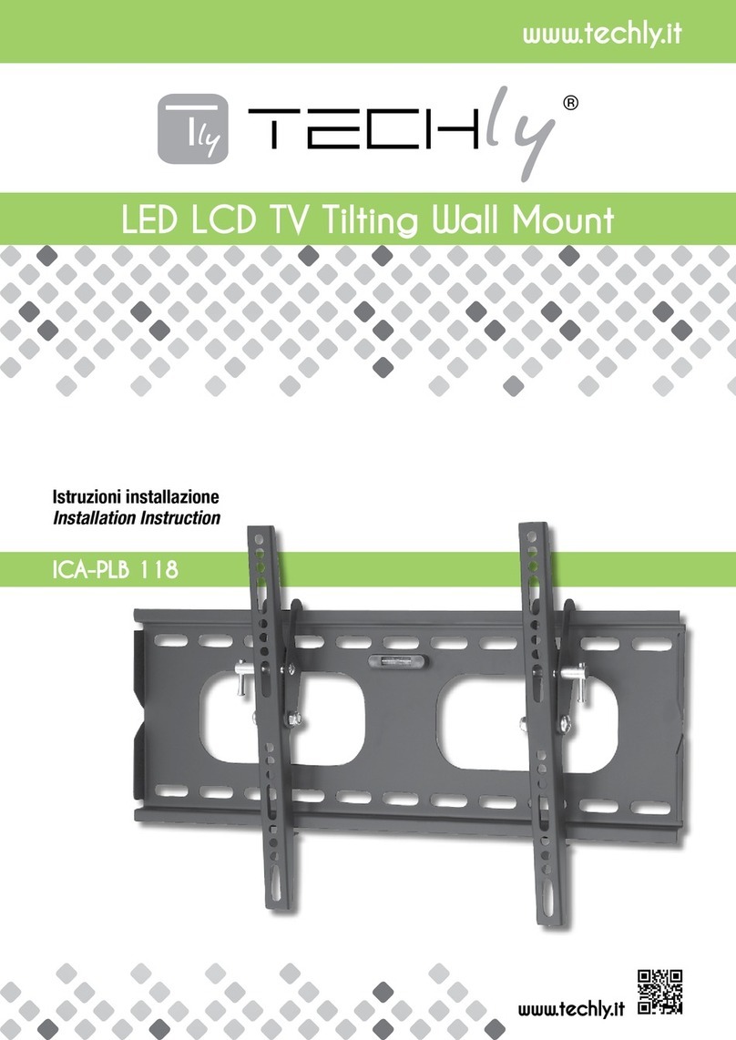
Techly ICA-PLB 101L User manual

www.techly.it
Istruzioni installazione
Installation Instruction
ULTRA-SLIM LED LCD TV Fixed Wall Mount
ICA-PLB 101L
www.techly.it

ULTRA-SLIM LED LCD TV Fixed Wall Mount
Gentile Cliente,
grazie per aver scelto un prodotto Techly.
Dear Customer,
thanks for choosing a Techly product. Enjoy the using.
Istruzioni disimballaggio
•Aprireilcartoneconcura,rimuovereilcontenutoedistenderlosu
uncartoneoaltromaterialeprotettivoperevitaredanni.
•Vericare che il contenuto della confezione corrisponda alla li-
stadellepartinellapaginasuccessivaperassicurarsichetuttii
componentisianopresentienonsianodanneggiati.Nonutilizzare
partidifettoseodanneggiate.
•Leggereattentamenteleistruzioniriportatenelpresentemanuale
primadiprocedereall’installazione.
•Teneresemprequestomanualeperfutureconsultazioni.
Importanti informazioni sulla sicurezza
Installareeutilizzarequestoprodottoconcura.Leggerecortesemente
leistruzioniprimadicominciarel’installazioneeseguirescrupolosa-
mentetutteleindicazionicontenutequi.Utilizzareadeguatidispositivi
disicurezzadurantel’intallazione.Contattaredelpersonalequalica-
topereffettuarel’installazione:
•Senonavetecompresoleindicazionicontenutein questo ma-
nualeoavetedeidubbiinmeritoallasicurezzadell’installazione;
•Senonsietesicuricircalatipologiadelmurodoveeffettuarel’in-
stallazionedelsupporto;
Nonutilizzateilprodottoperunoscopooinunacongurazionenon
espressamentespecicatainquesteistruzioni.Sideclinaqualsiasi
responsabilitàperdanniderivantidaunerratoassemblaggio,errato
montaggioousononcorrettodelprodotto.
Alterminedelleoperazionidimontaggioassicurarsicheiltuttosia
statoeffettuatoaregolad'arte.
Unpacking Instructions
• Carefully open the carton, remove contents and lay out on card-
board or other protective surface to avoid damage.
• Check package contents against the Supplied Parts List in the
next page to assure that all components were received undam-
aged. Do not use damaged or defective parts.
• Carefully read all instructions before attempting installation.
• Please keep the instruction manual for next consultations.
Important Safety Information
Install and operate this device with care.
Please read this instruction before beginning the installation, and
carefully follow all instructions contained herein.
Use proper safety equipment during installation.
Please call a qualied installation contractor for help if you:
• If you don't understand these directions or have any doubts about
the safety of the installation.
• If you are uncertain about the nature of your wall, consult a quali-
ed installation contractor.
Do not use this product for any purpose or in any conguration not
explicitly specied in this instruction. We hereby disclaims any and
all liability for injury or damage arising from incorrect assembly, in-
correct mounting, or incorrect use of this product.
At the end of the xing care that the support is installed in the cor-
rect way.
ATTENZIONE:QuestastaffaperlaTVdeveessere
ssataallapareteinmodosicuro.Seilmontaggio
nonèstatoeffettuatoinmodocorrettoestabile,
ciò potrebbe causare la caduta della staffa,
determinandolesioniodanniacoseepersone.
CAUTION: This TV mount must be securely
attachedtotheverticalwall.Ifthemountisnot
properlyinstalleditmayfall,resultinginpossible
injuryand/ordamage.
ATTREZZATURA RICHIESTA:
-Puntadeltrapanoda5/32”(4mm)
-CacciavitePhilips
-Puntadamuroda3/8”(10mm)
-Strumentoperindividuarel’intelaiaturadelmuro
-Livella
-Chiaveingleseosetcompletodichiavi
Nota: i componenti e il materiale di ssaggio forniti in questa
confezione non sono indicati per le installazioni su muri con
intelaiaturainacciaioosumuriconmattonidicemento.
Se il materiale di ssaggio di cui avete bisogno non è incluso,
consultatela vostraferramenta localeperindividuareilmateriale
dimontaggioindicatoperlavostraapplicazione.Ilproduttorenon
siassumealcunaresponsabilitàincasodiancoraggiononcorretto.
Assicurarsidell'integritàdelmuroprimadiprocedereall'installazione.
Rispettare tassativamente il peso massimo dell'apparecchiatura
supportataindicatonellaconfezione.
TOOLS REQUIRED:
-5/32"(4mm)DrillBit
-PhillipsScrewdriver
-3/8"(10mm)MasonryBit
-StudFinder
-WrenchorSocketSet
-Carpenter'sLevel
Note: The mounting components and hardware supplied in this
packagearenotdesignedforinstallationstowallswithsteelstuds
ortocinderblockwalls.
Ifthehardwareyouneedforyourinstallationisnotincluded,please
consultyourlocalhardwarestoreforpropermountinghardwarefor
theapplication.
Pleasepaycarefulattentiontowherethismountislocated,some
wallsarenotsuitableforinstallation.Respectthemaximumweight
limitationprintedonthebox.
LISTA DELLE PARTI FORNITE | SUPPLIED PARTS LIST
(1)Placcaamuro-a
(1)Wall Plate-a
(2)Staffamonitor-b
(2)Monitor Bracket-b
(4)M4x12Vite-C
(4)M4x12 Bolt-c
(4)M5x12Vite-d
(4)M5x12 Bolt-d
(4)M6x12Vite-e
(4)M6x12 Bolt-e
(4)M8x16Vite-f
(4)M8x16 Bolt-f
(4)M4Rondelladentellata-g
(4)M4 Lock Washer-g
(4)M5Rondelladentellata-h
(4)M5 Lock Washer-h
(4)M6Rondelladentellata-i
(4)M6 Lock Washer-i
(4)M8Rondelladentellata-j
(4)M8 Lock Washer-j
(4)M4/M5Rondella-k
(4)M4/M5 Washer-k
(4)M6/M8Rondella-l
(4)M6/M8 Washer-l
(3)Vitepertassello-m
(3)Lag Bolt-m
(3)Rondellapertassello-n
(3)Lag Bolt Washer-n
(3)Tassello-o
(3)Concrete Anchor-o
ULTRA-SLIM LED LCD TV Fixed Wall Mount

ULTRA-SLIM LED LCD TV Fixed Wall Mount
STEP 1 Montaggio delle staffe di supporto del monitor ad una TV con retro piatto
Mounting the Monitor Brackets to a TV with Flat Back
Primadituttovericateildiametro delleviti(c,d,e,f) richiestodallavostraTV.Appenaavete
determinatoildiametrocorretto,visionateloschemarelativosottoriportato.Doveteinlarelavite
nelforodellaTVutilizzandolacorrettarondelladentellata(g,h,i)erondellapiana(k,l).Assicu-
ratevichelestaffedisupportodelmonitor(b)sianocentrateverticalmenteeallostessolivello.
First of all, make sure the diameter of the Bolt(c,d,e,f) your TV requires. Once you have determined
the correct diameter, please see the relative diagram as below. You will thread the Bolt into the TV
using the correct Lock Washer(g,h,i,j) and Washer(k,l). Please make sure the Monitor Brackets(b)
are vertically centered and level with each other.
c
g
k
b
d
h
kb
e
l
b
f
j
lb
i
1 6 i n c h
1 6 i n c h
1 6 i n c h
mn
a
S tu d F i nd er
o
STEP 2 Fissaggio della placca a muro al muro | Mounting the Wall Plate to the Wall
Installazione su mattone, cemento armato o blocchi di calcestruzzo
Utilizzatelaplaccadamuro (a)comesagomapersegnare leposizionidei3foridaeffettuaresul
muro.Assicuratevicheiforisianoalivello.Praticareiforiconunapuntadatrapanoda10mmefate
inmodocheiforiabbianounaprofonditàdialmeno60mm(2,4").Inserireuntassello(o)inciasuno
diquestifori.Assicuratevicheitassellisianoinseriticompletamenteesianoaloconlasupercie
incalcestruzzo,anchese,frontalmente,vièunostratodicartongessoodialtromateriale.Fissatela
placcaamuroalmuroutilizzandole3vitiperitasselli(m),le3rondelledeitasselli(n)comemostrato
nelloschemainbasso.
Installazione su pareti con intelaiatura in legno
Laplaccaamuro(a)deveesseremontatasudueassidilegnoadalmeno406mmdidistanza.
Utilizzatel’appositostrumentoper individuaredueassivicine.Potrebbeessere unabuonaidea
vericaredoveleassisonoposizionateconunpunteruolooconchiodosottilecomemostratonello
schemaadestra.Praticateunforodi60mmdiprofonditàall’altezzadesideratainciasunaasse
utilizzandounapuntada4mm.Assicuratevicheiforisianoposizionatinellapartecentraledelle
assiechesianoallostessolivello.Fissatelaplaccaalmuroutilizzando2vitideitasselli(m)e2
rondelledeitasselli(n).
Brick, Solid Concrete and Concrete Block mounting:
Use the Wall Plate(a) as a template to mark 3 hole locations on the wall. Make sure these holes
are level. Pre-Drill these holes with a 3/8"(10mm) masonry bit to at least 2.4"(60mm) in depth.
Insert a Concrete Anchor(o) into each of these holes.
Make sure the anchor is seated completely ush with the concrete surface even if there is a layer
of drywall or other material in front. Attach the Wall Plate to the wall using 3pcs Lag Bolts(m) and
3pcs Lag Bolt Washers(n), shown in Diagram below in the left side.
Wood Stud mounting:
The Wall Plate(a) must be mounted to two wood studs at least 16"(406mm) apart. Use a stud
nder to locate two adjacent studs. It is a good idea to verify where the studs are located with an
awl or thin nail shown in the Diagram on the right side. Pre-drill a 2.4"(60mm) deep hole at the
desired height in each stud using a 5/32"(4mm) drill bit. Make sure these holes are in the center
area of the studs and level with each other. Attach the Wall Plate to the wall using the 2pcs Lag
Bolts(m) and 2pcs Lag Bolt Washers(n).
STEP 3 Installare il monitor alla placca a muro | Attaching Monitor to Wall Plate
ATTENZIONE: alcune televisioni per essere sollevate richiedono due persone! Il produttore
non è responsabile per eventuali danni a cose e persone.
Primaagganciatele staffedelmonitor (b)sulla partealta dellaplacca a muro(a),quindifate
ruotarelapartebassadellastaffadelmonitorversolaparteinferioredellastaffaamurocome
mostraloschemaA.Spingerelalaparteinferioredellatelevisioneperfareinmodochelestaffe
delmonitorsiaggancinoallaplaccaamuro.Oralatelevisioneèssataalsupportoamuro.Tirare
laparteinferioredellatelevisionepersganciareequindirimuoverelaTVdallaplaccamuro.Il
risultatonaledell’installazioneèvisibilenelloschemaB.
Warning: Some TVs may require two people to lift! We are not responsible for personal
injury or product damage.
First hook the Monitor Brackets(b) over the top of the Wall Plate(a), then let the bottom of the
Monitor Brackets rotate to the wall as shown in the Diagram A. Push the bottom of TV to let the
tap on the Monitor Brackets clip into the Wall Plate.
Then the TV will be xed on Wall Plate. Pull the bottom of TV to remove the TV from Wall Plate. The
nishing looking as shown in the Diagram B.
VitiM4
M4 Bolt
VitiM6
M6 Bolt
VitiM5
M5 Bolt
VitiM8
M8 Bolt
c
g
k
b
d
h
kb
e
l
b
f
j
lb
i
1 6 i n c h
1 6 i n c h
1 6 i n c h
mn
a
S tu d F i nd er
o
c
g
k
b
d
h
kb
e
l
b
f
j
lb
i
16 i n c h
16 i n c h
16 i n c h
mn
a
S tu d F ind e r
o
www.techly.it
ba
w a ll w a ll
ta p
Ta p s it b ehin d
w a ll p l a te
b
aganciosituatodietrolaplaccaamuro
tap sit behind wall plate
SchemaA
Diagram A
SchemaB
Diagram B
muro
wall
muro
wall
gancio
tap
Other Techly TV Mount manuals

Techly
Techly ICA-LCD 110BK User manual

Techly
Techly ICA-CPLB 946L User manual

Techly
Techly AV 100 User manual

Techly
Techly ICA-LCD 323M User manual

Techly
Techly ICA-CPLB 102 User manual

Techly
Techly ICA-PLB 162M User manual

Techly
Techly ICA-CS 62 User manual

Techly
Techly ICA-PLB 162M User manual

Techly
Techly ICA-TR32 User manual

Techly
Techly ICA-PLB 147 User manual

Techly
Techly ICA-PLB 104B User manual

Techly
Techly ICA-PLB 840 User manual

Techly
Techly ICA-LCD 2900B User manual

Techly
Techly LED 300 User manual

Techly
Techly ICA-PLB 118 User manual

Techly
Techly DESK 100 User manual

Techly
Techly iCa-PLB 133L User manual

Techly
Techly ICA-TR17T1 User manual

Techly
Techly ICA-CPLB 946S User manual

Techly
Techly ICA-PLB 162M User manual