technetix XGT XGTZ-2-4T User manual

technetix.com
+1 (720) 931-6480
12/2021-AE/V1
User manual
XGT 10 gigabit
modular outdoor taps

2XGT_User Manual
Contents
Safety 3
Intended audience 3
Tools list 3
Overview 4
Chapter 1 User applications
1.1 Mass deployment 5
1.2 Fixing the cables to the IN and OUT connectors 6
1.3 Base installation of IN and OUT connectors 7
1.4 Signal conditioning 7
1.5 Tightening sequence of faceplate bolts 8
1.6 Installing drop cables on a faceplate 8
1.7 Strand mount mechanism 9
Chapter 2 New builds and maintenance 9
2.1 Basic assembly 9
2.2 Bill of materials 10
2.3 Example installations 11
1. Install full tap 8-way 14 dB 11
2. Replace coupler module (CM)
without any power loss using
make before break tool (MBBT) 12
Order Information
Tap components 15
Coupler module removal tool (CMRT) 15
MBBT 15
Tap components 17
Signal conditioning 16

3technetix.com
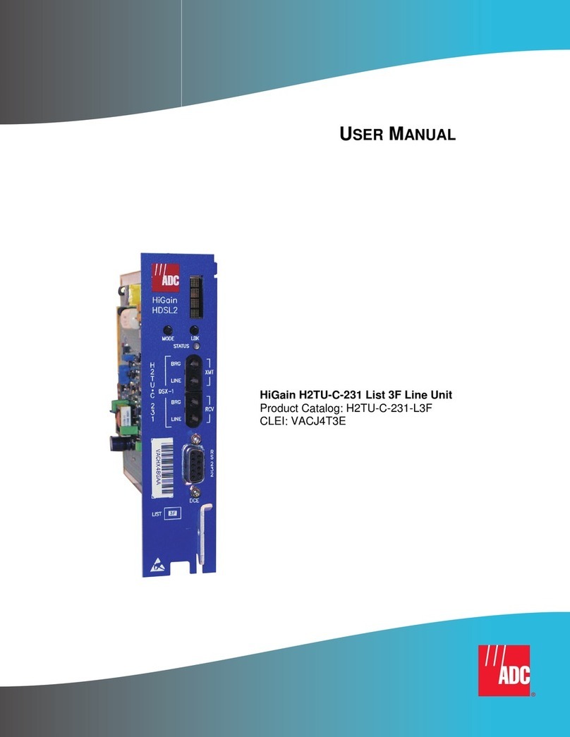
The XGT 10 gigabit modular outdoor tap user manual is intended for network engineers and
technicians responsible for planning, configuring, installing and testing the Technetix XGT
outdoor tap. Installers should have a working knowledge of coaxial cable and line powering
systems and cabling practices.
Tool list
The following tools and supplies are required when installing an XGT outdoor tap:
˺3/8" (10 mm) nut driver for lid bolts
˺Torque limiting spanner (wrench) tool 30 in/lbs (3.5 N-m) for F-connectors
˺Torque limiting spanner (wrench) tool 40 in/lbs (4.5 N-m) for KS 5/8 connectors
˺XGT-MBBT for power passing while removing coupler modules
˺XGT-CM-RT for easy removal of coupler modules
SAFETY
Warning: The center pin becomes live when the first connector is inserted – don’t touch anything else
with second connector – this will cause a shock.
PRODUCT INFORMATION: 19013994 XGT-MBBT XGT make before break tool
19014361 XGT-CM-RT XGT coupler module removal tool

4XGT_User Manual
Overview
˺Modular platform DOCSIS 4.11 compatible
˺3 GHz housing
˺1.8 GHz coupler module, also compatible with
1.2 GHz systems
˺1.8 GHz front plates: 2-way, 4-way and 8-way
˺Low inventory standardised modular solution2
˺one housing
˺three front plates
˺5 or 6 CM tap values
˺9 or 10 SKUs for a full multitap
˺3 GHz housing with superior seizure-less
connector design3
˺Faceplate removable without breaking
RFsignals and line power
˺Install now when upgrading or carrying out
routine maintenance:
˺1.2 GHz DOCSIS 3.1 ready now
˺1.8 GHz DOCSIS 4.0 ready now
˺3.0 GHz DOCSIS 4.1 ready housing
1Faceplate (XGT1800-FPx)
2Signal conditioning plug-in
3Directional coupler module (XGT1800-CMxx)
4Housing / Backbox (XGT3000-BB)
1. DOCSIS 4.1, the next generation after DOCSIS 4.0, taking bandwidth from 1.8 GHz to 3 GHz 25 Gbps data capacity.
2. With DOCSIS 4.1 all legacy Regal, GI-Moto, SA-Cisco and Magnavox housings become obsolete.
3. The futureproof XGT housing has enables a secure 3GHz connection without screws and excellent protection
against common path distortion (CPD).
1
2
3
4

5technetix.com
Fully assembled 2-way 1.8 GHz Fully assembled 4-way 1.8 GHz Fully assembled 8-way 1.8 GHz
XGTZ-2-4T
XGTZ-2-8 XGTZ-4-8T
XGTZ-2-11 XGTZ-4-11 XGTZ-8-11T
XGTZ-2-14 XGTZ-4-14 XGTZ-8-14
XGTZ-2-17 XGTZ-4-17 XGTZ-8-17
XGTZ-2-20 XGTZ-4-20 XGTZ-8-20
XGTZ-2-23 XGTZ-4-23 XGTZ-8-23
XGTZ-2-26 XGTZ-4-26 XGTZ-8-26
XGTZ-2-29 XGTZ-4-29 XGTZ-8-29
Item code Description
XGTZ-2-4T 10 gigabit taps facilitate the provision of 10 Gbit/s speeds to customers in the future
XGTZ-2-4T Z is a 1.8 GHz assembly (including the faceplate and CM)
XGTZ-2-4T 2-way faceplate
XGTZ-2-4T4 dB tap attenuation
XGTZ-2-4T Terminated housing for end-of-line situations
Chapter 1 User applications
1.1 Mass deployment
While the modularity of the XGT range is ideal for
maintenance and small deployments, it is recommended that
fully assembled multitaps are used for mass deployments
and entire network upgrades where 1 GHz and 1.2 GHz units
are all being replaced.
After a mass deployment it is recommended that individual
SKUs from the XGT range are used for ongoing maintenance
and upgrades to fully benefit from the modular approach and
the lower inventory requirements.

6XGT_User Manual
1.2 Installing cables to the IN and OUT connectors
The housing is fitted with a spring loaded 5/8 female connector (Fig. 1), designed to fit a standard KS 5/8 male connector
without the need to secure the pin with a screw contact (unlike legacy multitaps).
1. Cut the 5/8 pin to a length of 1.34” (34 mm) with a tolerance 0.039” (+/- 1 mm) also marked on the back
of the housing (Fig. 2).
2. The XGT 5/8 female connector takes pins with a diameter of 0.065” – 0.075” (1.65 - 1.91mm).
3. Torque the KS connectors to 40 in/lbs (4.5 N-m).
Pin length 1.34" (34 mm)
IMPORTANT: The total pin length = pin length and connector thread length (Fig. 3).
Fig.2
Fig. 1
Fig. 3

7technetix.com
1.3 Base installation of IN and OUT connectors
If installing a multitap and both cables come from the same direction, you can relocate the “blind plugs” to the side ports (Fig. 4),
making sure they are torqued at 40in/lbs (4.5 N-m), then the shielding eectiveness against 4G/5G signals remains high.
1.4 Signal Conditioning
Signal conditioning is used in certain networks to give a specific amount of tilt to the tap ports enabling them to reach homes
with a flat signal. In the XGT platform the signal conditioning plug-ins can be installed in the faceplate, which are all delivered
with a 0 dB jumper. When installing a cable equalizer or cable simulator, the 0 dB jumper in the faceplate will be replaced by the
signal conditioning plug-in.
Available plug-ins Cable simulator Cable equalizer
1.2 GHz optimized XGT1200-CSxx XGT1200-CExx
1.8 GHz optimized XGT1800-CSxx XGT1800-CExx
Fig. 4

8XGT_User Manual
1.5 Tightening sequence of faceplate bolts
Fully tighten to 30 in/lbs (3.5 N-m) in the following sequence:
1.6 Installing drop cables on the faceplate
Fix the F-male connector to the drop cables while connecting to customer premises at the front F-female ports of the
multitap, then tighten the connectors to 30 in/lbs (3.5 N-m) torque. Make sure all F-ports that are not in use are terminated
with a 75 Ohm terminator also to 30 in/lbs (3.5 N-m) torque.
4
1
2
3
Top bolt Bottom bolt Left hand bolt Right hand bolt
1 2 3 4

9technetix.com
1.7 Strand mount mechanism
Undo the bolt to secure the stand cable. Tighten the bolt to 30 in/lbs (3.5 N-m) torque.
Chapter 2 New builds and maintenance
The modularity of the XGT range is ideal for maintenance and small deployments, it is recommended that a fully assembled
multitap is used for mass deployments and entire network upgrades.
2.1 Basic assembly
Housing (backbox) + coupler module + faceplate = full multitap
+
+
=
=

10XGT_User Manual
Type Description
XGT3000-BB TECHNETIX 10 GIGABIT TAP BACK BOX 3.0 GHZ
XGT3000-BBT TECHNETIX 10 GIGABIT TAP BACK BOX 3.0 GHZ TERMINATED
XGT1800-FP2 TECHNETIX 10 GIGABIT TAP FACEPLATE 2-WAY
XGT1800-FP4 TECHNETIX 10 GIGABIT TAP FACEPLATE 4-WAY
XGT1800-FP8 TECHNETIX 10 GIGABIT TAP FACEPLATE 8-WAY
CM / dB value for the complete tap
2-way 4-way 8-way
XGT1800-CM0T TECHNETIX XGT DIRECTIONAL COUPLER MODULE 0T dB 4T 8T 11T
XGT1800-CM04 TECHNETIX XGT DIRECTIONAL COUPLER MODULE 04 dB 811 14
XGT1800-CM07 TECHNETIX XGT DIRECTIONAL COUPLER MODULE 07 dB 11 14 17
XGT1800-CM10 TECHNETIX XGT DIRECTIONAL COUPLER MODULE 10 dB 14 17 20
XGT1800-CM13 TECHNETIX XGT DIRECTIONAL COUPLER MODULE 13 dB 17 20 23
XGT1800-CM16 TECHNETIX XGT DIRECTIONAL COUPLER MODULE 16 dB 20 23 26
XGT1800-CM19 TECHNETIX XGT DIRECTIONAL COUPLER MODULE 19 dB 23 26 29
XGT1800-CM22 TECHNETIX XGT DIRECTIONAL COUPLER MODULE 22 dB 26 29 32
XGT1800-CM25 TECHNETIX XGT DIRECTIONAL COUPLER MODULE 25 dB 29 32 35
2.2 Bill of materials
Cross-reference the table below to determine the CMs required. The module number refers to the attenuation level
in dBs (to the faceplate). The faceplate adds the 2, 4 and 8-way splitter loss due to the number of ports on the faceplate.
The final values for tap loss are detailed in the table below.
A simple way to check that you have the correct couple module is to check the colored label. This will give you the dB values
the coupler will provide in combination with a 2, 4 or 8-way faceplate.

11technetix.com
2.3 Example installations
1. Install complete tap 8-way 35 dB
Check the tap value required and select the materials from your vehicle, no detailed materials planning is required for specific tap
values and faceplates combinations.
1. Select your parts using the guide on page nine.
One housing, one 8-way faceplate and one coupler module 25 dB (CM25)
(delivered with 29, 32 and 35 dB stickers)
2. Place the CM25 inside the housing and secure it by turning the placeholder 90° and tighten the screw.
3. Place the faceplate with dB sticker on the tap space with the arrow pointing in the same direction on the tap
as the arrow on the coupler module to indicate the directionality of the tap signal IN to OUT.

12XGT_User Manual
4. Install the drop cables on the F-ports with 30 in/lbs (3.5 N-m) torque and install the hardline cables on the in-and output
with 40 in/lbs (4.5 N-m) torque.
2. Replacing the CM without any power loss using the MBBT
If a coupler module is broken, or you need a dierent directional coupling to be applied – the XGT tap range ensures minimal
installation time and extremely short downtime. By using the XGT- MBBT you can bypass the multitap with RF signals and
15A of current while maintenance is being preformed on the coupler module.
1. Pick your material – one new CM and one XGT-MBBT.
2. Remove the faceplate from the tap (you can keep all the cables attached).

13technetix.com
3. Remove the blind plugs from the unused ports and place the MBBT in the two unused ports to bypass the power/RF signals.
4. Undo CM placeholders and remove the old CM from the tap using the CMRT (XGT-CM-RT).
WARNING: The center pin becomes live when the first connector is inserted – don’t touch anything else with
second connector – this will cause a shock.

14XGT_User Manual
5. Place the new CM in the tap, remove the MBBT from the tap and put the placeholders back in position.
6. Put the faceplate back on the tap. Replace the dB value sticker if necessary.
The correct dB value sticker is always delivered with the coupler modules.

15technetix.com
Separate tap components
Order separate components to deploy infrequently used tap values with cost eective post-installation maintenance.
Item number Item code Description
19013824 XGT3000-BB TECHNETIX XGT GIGABIT TAP HOUSING 3.0 GHZ
19013825 XGT3000-BBT TECHNETIX XGT GIGABIT TAP HOUSING 3.0 GHZ TERM
19013826 XGT1800-FP2 TECHNETIX XGT GIGABIT TAP FACEPLATE 2-WAY
19013827 XGT1800-FP4 TECHNETIX XGT GIGABIT TAP FACEPLATE 4-WAY
19013828 XGT1800-FP8 TECHNETIX XGT GIGABIT TAP FACEPLATE 8-WAY
dB value matrix coupler
module and faceplate version
2-way 4-way 8-way
19013838 XGT1800-CM0T TECHNETIX XGT DIRECTIONAL COUPLER MODULE 0T dB 4T 8T 11T
19013839 XGT1800-CM04 TECHNETIX XGT DIRECTIONAL COUPLER MODULE 04 dB 811 14
19013840 XGT1800-CM07 TECHNETIX XGT DIRECTIONAL COUPLER MODULE 07 dB 11 14 17
19013841 XGT1800-CM10 TECHNETIX XGT DIRECTIONAL COUPLER MODULE 10 dB 14 17 20
19013842 XGT1800-CM13 TECHNETIX XGT DIRECTIONAL COUPLER MODULE 13 dB 17 20 23
19013843 XGT1800-CM16 TECHNETIX XGT DIRECTIONAL COUPLER MODULE 16 dB 20 23 26
19013844 XGT1800-CM19 TECHNETIX XGT DIRECTIONAL COUPLER MODULE 19 dB 23 26 29
19013845 XGT1800-CM22 TECHNETIX XGT DIRECTIONAL COUPLER MODULE 22 dB 26 29 32
19013846 XGT1800-CM25 TECHNETIX XGT DIRECTIONAL COUPLER MODULE 25 dB 29 32 35
Complete multi tap units
Order complete units for large scale deployments
Item number Item code Description
2-way taps
19013904 XGTZ-2-4T TECHNETIX 10 GIGABIT TAP 2-WAY 4 dB 1.8 GHZ TERM
19013905 XGTZ-2-8 TECHNETIX 10 GIGABIT TAP 2-WAY 8 dB 1.8 GHZ
19013906 XGTZ-2-11 TECHNETIX 10 GIGABIT TAP 2-WAY 11 dB 1.8 GHZ
19013907 XGTZ-2-14 TECHNETIX 10 GIGABIT TAP 2-WAY 14 dB 1.8 GHZ
19013908 XGTZ-2-17 TECHNETIX 10 GIGABIT TAP 2-WAY 17 dB 1.8 GHZ
19013909 XGTZ-2-20 TECHNETIX 10 GIGABIT TAP 2-WAY 20 dB 1.8 GHZ
19013910 XGTZ-2-23 TECHNETIX 10 GIGABIT TAP 2-WAY 23 dB 1.8 GHZ
19013911 XGTZ-2-26 TECHNETIX 10 GIGABIT TAP 2-WAY 26 dB 1.8 GHZ
19013912 XGTZ-2-29 TECHNETIX 10 GIGABIT TAP 2-WAY 29 dB 1.8 GHZ
4-way taps
19013913 XGTZ-4-8T TECHNETIX 10 GIGABIT TAP 4-WAY 8 dB 1.8 GHZ TERM
19013914 XGTZ-4-11 TECHNETIX 10 GIGABIT TAP 4-WAY 11 dB 1.8 GHZ
19013915 XGTZ-4-14 TECHNETIX 10 GIGABIT TAP 4-WAY 14 dB 1.8 GHZ
19013916 XGTZ-4-17 TECHNETIX 10 GIGABIT TAP 4-WAY 17 dB 1.8 GHZ
19013917 XGTZ-4-20 TECHNETIX 10 GIGABIT TAP 4-WAY 20 dB 1.8 GHZ
19013918 XGTZ-4-23 TECHNETIX 10 GIGABIT TAP 4-WAY 23 dB 1.8 GHZ
19013919 XGTZ-4-26 TECHNETIX 10 GIGABIT TAP 4-WAY 26 dB 1.8 GHZ
19013920 XGTZ-4-29 TECHNETIX 10 GIGABIT TAP 4-WAY 29 dB 1.8 GHZ
8-way taps
19013921 XGTZ-8-11T TECHNETIX 10 GIGABIT TAP 8-WAY 11 dB 1.8 GHZ TERM
19013922 XGTZ-8-14 TECHNETIX 10 GIGABIT TAP 8-WAY 14 dB 1.8 GHZ
19013923 XGTZ-8-17 TECHNETIX 10 GIGABIT TAP 8-WAY 17 dB 1.8 GHZ
19013924 XGTZ-8-20 TECHNETIX 10 GIGABIT TAP 8-WAY 20 dB 1.8 GHZ
19013925 XGTZ-8-23 TECHNETIX 10 GIGABIT TAP 8-WAY 23 dB 1.8 GHZ
19013926 XGTZ-8-26 TECHNETIX 10 GIGABIT TAP 8-WAY 26 dB 1.8 GHZ
19013927 XGTZ-8-29 TECHNETIX 10 GIGABIT TAP 8-WAY 29 dB 1.8 GHZ
Order Information

16XGT_User Manual
Signal conditioning plug-ins
Item number Item code Description
1.2 GHz cable equalizers
19013880 XGT1200-CE02 TECHNETIX XGT PLUG-IN CABLE EQUALIZER 02 dB 1.2 GHZ
19013881 XGT1200-CE03 TECHNETIX XGT PLUG-IN CABLE EQUALIZER 03 dB 1.2 GHZ
19013882 XGT1200-CE04 TECHNETIX XGT PLUG-IN CABLE EQUALIZER 04 dB 1.2 GHZ
19013883 XGT1200-CE06 TECHNETIX XGT PLUG-IN CABLE EQUALIZER 06 dB 1.2 GHZ
19013884 XGT1200-CE08 TECHNETIX XGT PLUG-IN CABLE EQUALIZER 08 dB 1.2 GHZ
19013885 XGT1200-CE09 TECHNETIX XGT PLUG-IN CABLE EQUALIZER 09 dB 1.2 GHZ
19013886 XGT1200-CE10 TECHNETIX XGT PLUG-IN CABLE EQUALIZER 10 dB 1.2 GHZ
19013887 XGT1200-CE12 TECHNETIX XGT PLUG-IN CABLE EQUALIZER 12 dB 1.2 GHZ
19013888 XGT1200-CE14 TECHNETIX XGT PLUG-IN CABLE EQUALIZER 14 dB 1.2 GHZ
19013889 XGT1200-CE16 TECHNETIX XGT PLUG-IN CABLE EQUALIZER 16 dB 1.2 GHZ
19013890 XGT1200-CE18 TECHNETIX XGT PLUG-IN CABLE EQUALIZER 18 dB 1.2 GHZ
19013891 XGT1200-CE20 TECHNETIX XGT PLUG-IN CABLE EQUALIZER 20 dB 1.2 GHZ
19013892 XGT1200-CE22 TECHNETIX XGT PLUG-IN CABLE EQUALIZER 22 dB 1.2 GHZ
1.8 GHz cable equalizers
19013856 XGT1800-CE02 TECHNETIX XGT PLUG-IN CABLE EQUALIzER 02 dB 1.8 GHZ
19013857 XGT1800-CE03 TECHNETIX XGT PLUG-IN CABLE EQUALIZER 03 dB 1.8 GHZ
19013858 XGT1800-CE04 TECHNETIX XGT PLUG-IN CABLE EQUALIZER 04 dB 1.8 GHZ
19013859 XGT1800-CE06 TECHNETIX XGT PLUG-IN CABLE EQUALIZER 06 dB 1.8 GHZ
19013860 XGT1800-CE08 TECHNETIX XGT PLUG-IN CABLE EQUALIZER 08 dB 1.8 GHZ
19013861 XGT1800-CE09 TECHNETIX XGT PLUG-IN CABLE EQUALIZER 09 dB 1.8 GHZ
19013862 XGT1800-CE10 TECHNETIX XGT PLUG-IN CABLE EQUALIZER 10 dB 1.8 GHZ
19013863 XGT1800-CE12 TECHNETIX XGT PLUG-IN CABLE EQUALIZER 12 dB 1.8 GHZ
19013864 XGT1800-CE14 TECHNETIX XGT PLUG-IN CABLE EQUALIZER 14 dB 1.8 GHZ
19013865 XGT1800-CE16 TECHNETIX XGT PLUG-IN CABLE EQUALIZER 16 dB 1.8 GHZ
19013866 XGT1800-CE18 TECHNETIX XGT PLUG-IN CABLE EQUALIZER 18 dB 1.8 GHZ
19013867 XGT1800-CE20 TECHNETIX XGT PLUG-IN CABLE EQUALIZER 20 dB 1.8 GHZ
19013868 XGT1800-CE22 TECHNETIX XGT PLUG-IN CABLE EQUALIZER 22 dB 1.8 GHZ
Order Information

Order Information
If you would like further information on the content of this user manual, please contact:
Maarten Markhorst
Director of Connected Home Products
maarten.markhorst @technetix.com
+31 318 58 59 59
Signal conditioning plug-ins
Item number Item code Description
1.2 GHz cable simulators
19013893 XGT1200-CS02 TECHNETIX XGT PLUG-IN CABLE SIMULATOR 02 DB 1.2 GHZ
19013894 XGT1200-CS03 TECHNETIX XGT PLUG-IN CABLE SIMULATOR 03 DB 1.2 GHZ
19013895 XGT1200-CS04 TECHNETIX XGT PLUG-IN CABLE SIMULATOR 04 DB 1.2 GHZ
19013896 XGT1200-CS06 TECHNETIX XGT PLUG-IN CABLE SIMULATOR 06 DB 1.2 GHZ
19013897 XGT1200-CS08 TECHNETIX XGT PLUG-IN CABLE SIMULATOR 08 DB 1.2 GHZ
19013898 XGT1200-CS09 TECHNETIX XGT PLUG-IN CABLE SIMULATOR 09 DB 1.2 GHZ
19013899 XGT1200-CS10 TECHNETIX XGT PLUG-IN CABLE SIMULATOR 10 DB 1.2 GHZ
19013900 XGT1200-CS12 TECHNETIX XGT PLUG-IN CABLE SIMULATOR 12 DB 1.2 GHZ
19013901 XGT1200-CS15 TECHNETIX XGT PLUG-IN CABLE SIMULATOR 15 DB 1.2 GHZ
19013902 XGT1200-CS18 TECHNETIX XGT PLUG-IN CABLE SIMULATOR 18 DB 1.2 GHZ
19013903 XGT1200-CS21 TECHNETIX XGT PLUG-IN CABLE SIMULATOR 21 DB 1.2 GHZ
19013891 XGT1200-CE20 TECHNETIX XGT PLUG-IN CABLE SIMULATOR 20 DB 1.2 GHZ
19013892 XGT1200-CE22 TECHNETIX XGT PLUG-IN CABLE SIMULATOR 22 DB 1.2 GHZ
1.8 GHz cable simulators
19013869 XGT1800-CS02 TECHNETIX XGT PLUG-IN CABLE SIMULATOR 02 DB 1.8 GHZ
19013870 XGT1800-CS03 TECHNETIX XGT PLUG-IN CABLE SIMULATOR 03 DB 1.8 GHZ
19013871 XGT1800-CS04 TECHNETIX XGT PLUG-IN CABLE SIMULATOR 04 DB 1.8 GHZ
19013872 XGT1800-CS06 TECHNETIX XGT PLUG-IN CABLE SIMULATOR 06 DB 1.8 GHZ
19013873 XGT1800-CS08 TECHNETIX XGT PLUG-IN CABLE SIMULATOR 08 DB 1.8 GHZ
19013874 XGT1800-CS09 TECHNETIX XGT PLUG-IN CABLE SIMULATOR 09 DB 1.8 GHZ
19013875 XGT1800-CS10 TECHNETIX XGT PLUG-IN CABLE SIMULATOR 10 DB 1.8 GHZ
19013876 XGT1800-CS12 TECHNETIX XGT PLUG-IN CABLE SIMULATOR 12 DB 1.8 GHZ
19013877 XGT1800-CS15 TECHNETIX XGT PLUG-IN CABLE SIMULATOR 15 DB 1.8 GHZ
19013878 XGT1800-CS18 TECHNETIX XGT PLUG-IN CABLE SIMULATOR 18 DB 1.8 GHZ
19013879 XGT1800-CS21 TECHNETIX XGT PLUG-IN CABLE SIMULATOR 21 DB 1.8 GHZ
XGT maintenance tools
Item number Item code Description
19014361 XGT-CM-RT XGT COUPLER MODULE REMOVAL TOOL
19013994 XGT-MBBT XGT MAKE BEFORE BREAK TOOL
© Copyright 2021 Technetix Group Limited. All rights reserved.
This document is for information only. Features and specifications are subject to change without notice. Technetix, the Technetix logo and certain other
marks and logos are trade marks or registered trade marks of Technetix Group Limited in the UK and certain other countries. Other brand and company
names are trade marks of their respective owners. Technetix protects its technology and designs by registering patents, trade marks and designs in
Europe and certain other countries.
This manual suits for next models
23
Table of contents
Other technetix Network Hardware manuals
Popular Network Hardware manuals by other brands
Firmtech
Firmtech FBL601BC Series user manual
Siklu
Siklu MultiHaul TG Installation, operation and maintenance manual
Cisco
Cisco Aironet 340 Series quick start guide
Strand Lighting
Strand Lighting 65161 quick start guide

Polycom
Polycom Video Media Center VMC 1000 Getting started guide
Juniper
Juniper Junos Space JA1500 installation guide

