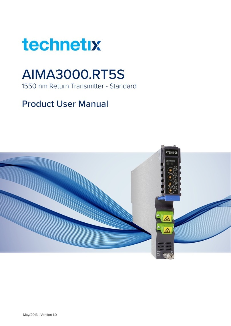
technetix AIMA3000-FT5E Operational manual

AIMA3000-FT5E
1550 NM
FORWARD
TRANSMITTER
ENHANCED
Online
Email: customer.service.[email protected]
Website: technetix.com
Oct/2017 - V1
Technetix Group Limited
Product User Manual

Oct/2017 - V1
Product User Manual
AIMA-FT5E
Technetix Group Limited
Contents
1 Manual Guide.............................................................................................................................................................1
1.1 Precautions...............................................................................................................................................................................................1
1.2 Related Documentation........................................................................................................................................................................2
1.3 Technical Support...................................................................................................................................................................................2
2 Introduction ...............................................................................................................................................................3
2.1 Overview ...................................................................................................................................................................................................3
2.2 Features.....................................................................................................................................................................................................3
2.3 Specifications...........................................................................................................................................................................................4
2.4 Order Details............................................................................................................................................................................................5
3 Technical Description ...................................................................................................................................................6
3.1 Block Diagram ..............................................................................................................................................................................................6
3.2 FT5E Module Structure............................................................................................................................................................................7
3.2.1 FT5E Module Appearance.............................................................................................................................................................7
3.2.2 FT5E Module Front/Back Panel Layout....................................................................................................................................7
4 Installation.................................................................................................................................. ....................................9
4.1 Packing List ...................................................................................................................................................................................................9
4.2 Packaging and Transportation...............................................................................................................................................................9
4.3 Installation and Wiring ..............................................................................................................................................................................9
4.3.1 Installation............................................................................................................................................................................................9
4.3.2 FT5E Wiring .......................................................................................................................................................................................9
4.3.3 LED Indicator Lights ........................................................................................................................................................................12
5 Module Configuration and Alarms.............................................................................................................................13
5.1 Module Configuration................................................................................................................................................................................13
5.1.1 FT5E Module Configuration Details .............................................................................................................................................13
5.1.2 FT5E Port Configuration Details...................................................................................................................................................15
5.1.3 Automatically Uploading/Downloading Module Configuration..........................................................................................17
5.2 Alarms............................................................................................................................................................................................................18
5.2.1 FT5E Module Alarms .......................................................................................................................................................................18
5.2.2 FT5E Port Alarms.............................................................................................................................................................................19
5.3 System Logs ................................................................................................................................................................................................20
5.4 Module Upgrades......................................................................................................................................................................................21
CAUTION............................................................................................................................................................................22
5.5 Module Operating Range .......................................................................................................................................................................22
5.5.1 94CH QAM (including OFDM) Environment .............................................................................................................................22
6 Troubleshooting ............................................................................................................................................................23
8 Declaration of Conformity ...........................................................................................................................................24
Appendix A: Description of LED Indicator Lights .......................................................................................................25

1Oct/2017 - V1 Technetix Group Limited
Product User Manual
AIMA-FT5E
1 Manual Guide
1.1 Precautions
WARNING!
This equipment is intended for indoor applications. To prevent fire or electrical shock, or damage
to the equipment, do not expose units to water or moisture.
■You should carefully read and thoroughly understand the contents of the manual before installing
and using this equipment.
■A typical connector is the SC/APC 8°.
Note: An 8° angle polished optical connectors must be used.
■At any time, there may be dangerous voltage inside the device.
■Do not power up before the cover and the panels of the equipment are installed and the enclosure
is closed.
Cleaning:
Only use a damp cloth for cleaning the front panel. Use a soft dry cloth to clean the top of the unit.
DO NOT use any spray cleaners or chemicals of any kind.
Outage or overload requiring service and repairs:
Unplug the unit and refer only to Technetix's qualified service personnel.
Servicing and repairs:
DO NOT attempt to service this unit yourself. Refer all servicing needs to Technetix's qualified service
personnel only.
WARNING!
Exposure to class 3A laser radiation is possible. Access should be restricted to
trained personnel only. Do not view exposed fibre or connector ends when handling
optical equipment.

2Oct/2017 - V1 Technetix Group Limited
Product User Manual
AIMA-FT5E
1.2 Related Documentation
Documents listed below can be used in association with this manual:
- Technetix.AIMA3000 - Product User Manual
- Technetix.AIMA ASMM - Product User Manual
- AIMA3000 NMS Web Management System Product User Manual
- Technetix.NMS3-EPSM - Basic Inventory Management
- Technetix.NMS3-EPSM - Basic Alarm Management
- Technetix.NMS3-EPSM - Basic System Management
- Technetix.NMS3-EPSM - Basic Template Management
1.3 Technical Support
If you need help in the process of setting up and maintaining an FT5E, please contact Technetix’s technical
support sta:
Europe:
Technetix BV
Kazemat 5
NL-3905 NR Veenendaal
P.O. Box 385
NL-3900 AJ Veenendaal
The Netherlands
Phone: +31 318 58 59 59

3Oct/2017 - V1 Technetix Group Limited
Product User Manual
AIMA-FT5E
2 Introduction
2.1 Overview
The 1550 nm Forward Transmitter – Enhanced (FT5E) is designed to plug into the Technetix latest Advanced Intelligent
Multi-services Access platform – the AIMA3000.
The FT5E supports DOCSIS 3.1 technical standards. It allows for broadcast and narrowcast dual RF inputs, providing
individual amplifying and transmission gain configuration for each circuit. The module’s operating wavelength conforms to
ITU standards and works with the Erbium Doped Fibre Amplifier Modules (EDFA), satisfying a growing demand for multi-
application modules. The module supports dual-channel configuration. It can be used in HFC 1550 nm optical transmission
systems and eectively improves network performance.
The FT5E employs an advanced RF circuit design and a high-quality/low-chirp laser with stable optical modulation,
ensuring high-performance optical output.
2.2 Product Key Features
■Plug-and-Play (PnP)
■High quality 1550 nm low-chirp analog DFB laser
■RF amplifier gain blocks with advanced GaAs technology
■Conforms to ITU wavelength DWDM standards
■Frequency response of 45 MHz to 1218 MHz for both broadcast and narrowcast applications
■Automatic gain control (AGC) for a consistent optical modulation index (OMI)
■Automatic thermo-cooler control (ATC) for a consistent laser temperature
■Automatic power control (APC) for a consistent optical output power
■Fully FCC, CE, and RCM compliant1
1. See Declaration of Conformity.

4Oct/2017 - V1 Technetix Group Limited
Product User Manual
AIMA-FT5E
2.3 Specifications
Optical Performance
Optical wavelength ITU channels 21 to 51
Optical outputs 2
Output power 8 dBm, 9 dBm, 10 dBm
Optical connector SC/APC1, FC/APC, LC/APC, E2000/APC
Laser RIN < 155 dB/Hz
RF Performance
RF bandwidth 45~1218 MHz
RF flatness ±0.75 dB
RF input level (BC)210 dBmV per channel (117 channel QAM256)
13 dBmV per channel (77 NTSC)
RF input level (NC)220 dBmV per channel (117 channel QAM256)
AGC range ±3 dB
Isolation between BC and NC inputs >45 dB
RF impedance 75
RF input return loss >16 dB
RF test point 20±1 dB
Transmitter isolation >65 dB
RF input connector 4 GSK female (2 for NC and 2 for BC)
RF test points Mini-SMB×43
Alarms Front-panel LEDs, SNMP Traps
Link Performance
CNR CSO CTB MER BER
NTSC+QAM4> 50 dB > 55 dB > 60 dB > 39 dB < 1E-9
QAM(20Km)5- - - > 41 dB < 1E-9
QAM(40Km)5- - - > 39 dB < 1E-9
1. Standard option. Contact a Technetix sales representative for availability of other options.
2. dBuV=60+dBmV.
3. Two ports for NC inputsand two for laser RF level.
4. CNR/CSO/CTB are tested with 77 NTSC CW channels (55.25MHz-547.25MHz). MER and BER are tested with 110 QAM256. All parameters are measured using a Technetix reference receiver, 10 km fibre,
and 0 dBm input level.
5. MER and BER are tested with 117 QAM256 (ITU-TJ.83 Annex A). All parameters are measured using a Technetix reference receiver, 20/40 km fibre, and 0 dBm input level.

5Oct/2017 - V1 Technetix Group Limited
Product User Manual
AIMA-FT5E
General
Power supply Powered via AIMA3000 backplane
Power consumption <19 W
Operating conditions Temperature: -5~55 °C;
Relative humidity: ≤90% (non-condensing)
Storage conditions Temperature: -40~70 °C;
Relative humidity: ≤90% (non-condensing)
Dimensions (W*D*H) 24.6×410×152.5 mm (W×D×H)
Weight 1 kg
2.4 Order Details
A-FT5E-[V]-[W]-[X]-[Y]-[Z] AIMA3000 1550 nm Forward Transmitter - Enhanced
Options:
V Optical ports
DDual (2)
W Optical output power per port
08 8 dBm (6.3 mw)
09 9 dBm (8 mw)
10 10 dBm (10 mw)
X Wavelength
21 192.1 THz (1560.61 nm)
22 192.2 THz (1559.79 nm)
23 192.3 THz (1558.98 nm)
25 192.5 THz (1557.36 nm)
27 192.7 THz (1555.75 nm)
29 192.9 THz (1554.13 nm)
31 193.1 THz (1552.52 nm)
33 193.3 THz (1550.92 nm)
35 193.5 THz (1549.32 nm)
.... ....
51 195.1 THz (1549.32 nm)
Y Optical connector type
SSC / APC (2)
LLC/APC
FFC/APC
EE2000/APC
Z Bandwidth
12 45-1218 MHz
1. Default spacing is 200 GHz. For other wavelength configurations not listed,
please contact Technetix.
2. Standard option. Contact a Technetix sales representative for availability of
other options.

6Oct/2017 - V1 Technetix Group Limited
Product User Manual
AIMA-FT5E
3 Technical Description
3.1 Block Diagram
Table 3-1 FT5E circuit components
Figure 3-1 FT5E block diagram
Component Description
NC
-20 dB TP
BC
Attenuator/Atten
Gain
Slope
-20dB OMI TP
OMI ADJ.
Pre-D
Total OMI
To back panel and comms Connection chassis back panel (module power supply and communication interface)
CPU Microprocessor
Laser Laser
Optical output 1 Optical output port 1
Optical output 2 Optical output port 2

7Oct/2017 - V1 Technetix Group Limited
Product User Manual
AIMA-FT5E
3.2 FT5E Module Structure
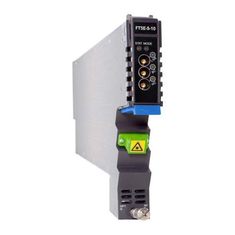
3.2.1 FT5E Module Appearance
3.2.2 FT5E Module Front/Back Panel Layout
Figure 3-2 FT5E module
Figure 3-3 FT5E front panel layout Figure 3-4 FT5E back panel layout

8Oct/2017 - V1 Technetix Group Limited
Product User Manual
AIMA-FT5E
Table 3-2 FT5E front panel components
Table 3-3 FT5E back panel components
No. Component Description
1 Lever
2 LED indicator See Appendix A for more details about LED indicator lights
3 Channel 1 laser RF level test point 20±1 dB
4 Channel 1 narrowcast intput test point 20±1 dB
5 Channel 2 laser RF level test point 20±1 dB
6 Channel 2 narrowcoast input test point 20±1 dB
7 Button
8 Optical output port 1
9 Optical output port 2
10 Fastening screw
No. Component Description
1 Narrowcast input port 1
2 Broadcast input port 1
3 Narrowcast input port 2
4 Broadcast input port 2
5 Air vent
6 Multi-pin port Connection chassis back panel (module power)
7 Alignment pin For easier positioning during module installation
WARNING!
When the FT5E is operating, the optical output port will produce non-visible laser radiation.

9Oct/2017 - V1 Technetix Group Limited
Product User Manual
AIMA-FT5E
4 Installation
4.1 Packing List
On receiving your new FT5E, carefully unpack and examine the contents for damage or loss that may have occurred
during shipping. If any items are missing or damaged, refer to the product warranty terms and contact Technetix. The FT5E
package should consist of the following:
Table 4-1 FT5E packing list
Item Qty
FT5E module 1
Factory inspection report 1
4.2 Packaging and Transportation
Keep all boxes and packaging provided for the FT5E for future transport.
Use only the original packaging for transporting the FT5E, as it has been specifically designed to protect this product.
4.3 Installation and Wiring
4.3.1 Installation
Conduct the following inspections after unpacking the FT5E:
■Check the FT5E module’s multi-pin connectors for damage and deformation.
■Check whether the FT5E case is damaged and whether screws are loose, have fallen out, or are missing.
■Check whether the Technetix name plate on the module is intact and write down the module’s model, serial number,
and date of production.
If any issues arise during the inspection, please contact Technetix technical support. Install the FT5E into any application
module slot in the chassis.1
1. See 'Technetix.AIMA3000 Product User Manual' for information about module installation.

10Oct/2017 - V1 Technetix Group Limited
Product User Manual
AIMA-FT5E
4.3.2 FT5E Wiring
Before wiring, determine the FT5E RF input power based on the number of channels (broadcast or broadcast +
narrowcast). Set the parameters for the 'AGC model,' 'BC MGC,' or 'NC MGC' in the AIMA3000 configuration system
according to the actual input RF power, and set the parameters for the alarms.
See Chapter 5.1.2 for more information about parameters in the FT5E module port configuration interface.
a. Connect narrowcast and broadcast RF input cables to the narrowcast and broadcast input ports on the back panel of
the FT5E, respectively.
b. Check whether the 'RF11' indicator light on the module’s front panel is green. If it is green, proceed to the next step. If the
'RF1' indicator light is orange or red, connect a spectrum analyzer to the broadcast and narrowcast input test points to
measure broadcast and narrowcast input power. According to the obtained values, make adjustments to the broadcast
and narrowcast input signals or the 'BC MGC' and 'NC MGC' parameter settings for the corresponding ports until the 'RF'
indicator light turns green.
c. Check whether the 'LSR' indicator light is green. If it is green, proceed to the next step.
If the indicator light is orange, check the FT5E port alarm interface in the AIMA3000 configuration system and ensure
that the laser temperature, bias current, and output power are within the normal range. If values are not within the
normal range, make adjustments according to the parameters of the alarm information until the values reach a normal
range. If the indicator light is red, check whether 'Laser Output' in the AIMA3000 configuration system FT5E port alarm
interface is switched on. If the 'Laser Output' is switched o, set 'Laser Output Control' in the FT5E port alarm interface
to 'On.' If the LSR indicator light is still red, check whether the laser temperature, bias current, and output power are
within the normal range. If values are not within the range, make adjustments according to the parameters of the alarm
information until the values reach the normal range.
d. Thread the fibre optic cables from the module’s back panel to the front panel using the fibre guide. Arrange the cables
in the fibre optic channel guide and fix them in the channel guide’s grooves.3
e. Clean the fibre optic contact and optical output port (located on the front panel of the module).
1. RF2 and LSR indicator lights function the same way as RF1 and LSR1.
2. The FT5E module’s 'NC RF Total Input Power' alarm is set to 'o' by default. Before checking the RF indicator lights, log in to the AIMA3000 configuration system and turn on the main and secondary
alarms (select HiHi/Hi/Lo/LoLo threshold values).
3. See AIMA3000 Manual for information about using the fibre guide and wiring fibre optic cables.

11Oct/2017 - V1 Technetix Group Limited
Product User Manual
AIMA-FT5E
To obtain a good quality optical input signal, optical fibre input ports and fibre connector ends must be carefully cleaned.
Head
Connection terminal
When cleaning the optical fibre-connector end, remove the dust cap and then use a lint-free cloth dampened with a static
dissipative solvent to clean the angled surface. Dry the surface using a dry lint-free cloth.
To clean the front-panel optical port, use a special lint-free swab that is designed for this purpose. Dampen it with a static
dissipative solvent. Apply slight pressure to the internal angled surface of the optical port, while rotating the swab
90 degrees back and forth. You may need to remove excess solvent using a dry lint-free swab. Alternatively, a cleaning
pen such as the one click cleaner can be used. Always inspect the fibre-end interfaces using an appropriate scope to
validate that the surfaces are adequately clean, free from damage, and dry from any solvents prior to connection.
Figure 4-1 The fibre connector ends
SC one click cleaning pen
www.oneclickcleaner.com

12Oct/2017 - V1 Technetix Group Limited
Product User Manual
AIMA-FT5E
f. Align the contact pins on the end face of the fibre optic contact with the grooves in the optical output port, and then
insert the fibre optic contact, as shown in the figure. There will be a clicking sound when the contact is in place.
Figure 4-2. Connecting a fibre optic cable
Optical output port
Fibre optic cable contact
WARNING!
The FT5E module must be installed and maintained by professionally trained personnel following
safe operating procedures.
If the FT5E has idle ports and input ports, terminate them with a 75-Ω resistive load to avoid
damage to the product.
WARNING!
The FT5E will produce invisible radiation during operation. Do not touch or directly look into
fibre optic cable contacts and other related components.
4.3.3 LED Indicator Lights
After the module is installed and connected to a power supply, green indicator lights on the front panel indicate that the
module is on.
If the input and output signals are normal, the 'STAT' indicator light will stop flickering after 5 seconds and remain green.
The 'LSR1', 'RF1', 'LSR2', and 'RF2' indicator lights should be also green.
If one of broadcast/narrowcast RF input signals is too low or too high, the 'STAT' and 'RF' indicator lights may be orange or
red. 1
If an optical output signal is too low or too high, the 'STAT' and 'LSR' indicator lights may be orange or red.
See Appendix A for more information about FT5E indicator lights.
1. The FT5E module’s 'NC RF Total Input Power' alarm is set to o by default. When the BC RF total input power is normal, the RF indicator light remains green. Before checking the RF indicator lights, log
in to the AIMA3000 configuration system and turn on the main and secondary alarms (select HiHi/Hi/Lo/LoLo threshold values).

13Oct/2017 - V1 Technetix Group Limited
Product User Manual
AIMA-FT5E
5 Module Configuration and Alarms
The FT5E module can be configured via the ASMM web interface or Technetix web-based NMSE system.
This manual only provides instructions for configuration using the ASMM web interface. See the NMSE manual for
configuration using Technetix web-based NMSE system.
5.1 Module Configuration
5.1.1 FT5E Module Configuration Details
Select the 'Modules' option in the AIMA3000 configuration system interface. Select the FT5E module from the module list
on the left (see Figure 5-1). The white area on the right side of the interface shows the FT5E module configuration details.
Ports are listed under the FT5E module name in the module list on the left. When a port is selected from the list, the port
configuration details are displayed in the white area on the right (see Chapter 5.1.2, Figure 5-2).
Figure 5-1 FT5E module configuration interface
FT5E module configuration details include four parts: module information, configuration, alarm settings,
and module management.

14Oct/2017 - V1 Technetix Group Limited
Product User Manual
AIMA-FT5E
Module details (read-only); the displayed items and button functions are as follows:
Alarm settings; parameters and button functions are as follows:
Module Management; push button functions are as follows:
Configuration; parameter descriptions and button functions are as follows:
Item Description
'Module Information' Model, serial No, HW Assembly No, FW Part No, FW Version.
'Refresh' Refreshes the web GUI.
Item Description
'Temperature'/ '+12V Input Voltage'/
'+5V Input Voltage'/ '-5V Input
Voltage'
Select or unselect parameters to determine alarm settings and levels. However, the user cannot change the
alarm threshold values and blind spot settings.
See Table 5-1 for the default settings for each parameter.
'Submit' Saves changes to setting.
Item Description
'Factory Defaults' When the 'Apply' button is pressed, all FT5E settings are cleared and restored to default. After this process is
completed, the module is automatically rebooted.
'Reboot' Reboots the module. This action requires approximately 20 seconds.
Item Description
'Alarm Control'
'Enable' - enables the alarm monitoring function; an alarm is triggered only when a malfunction occurs. The
indicator lights on the module alarm status interface (Chapter 5.2.1, Figure 5-4) change in accordance with the
actual situation.
'Disable' - disables the alarm monitoring function; the alarm status will remain as it was before
being disabled and will not change.
'Tx Unit Control' 'On' - enables individual optical output for all port lasers (default);
'O' - disables optical output for all port lasers.
'Module Alias' Sets module names; after confirming, the module name will be updated in the corresponding FT5E slot in the list
on the left side of the interface.
'Submit' Saves changes to settings.

15Oct/2017 - V1 Technetix Group Limited
Product User Manual
AIMA-FT5E
Table 5-1 FT5E default alarm settings
Parameter Unit HiHi Hi Lo LoLo
Temperature °C √ √ √ √
+12V Input Voltage V √ - - √
+5V Input Voltage V √ - - √
-5V Input Voltage V √ - - √
Note:
'√' When the parameter value in the selected check box exceeds the threshold value, the corresponding alarm is triggered. When the values are
between the Hi and Lo threshold values, the alarm status is normal (no alarm). The secondary alarm is triggered if the Hi (Lo) threshold value
is exceeded. The main alarm is triggered if the HiHi (LoLo) threshold value is exceeded.
'' o settings available.
5.1.2 FT5E Port Configuration Details
The port configuration interface is opened by selecting a port name under the FT5E module in the list on the left side, as
shown in Figure 5-2.
Figure 5-2 FT5E port configuration interface

16Oct/2017 - V1 Technetix Group Limited
Product User Manual
AIMA-FT5E
FT5E port configuration details include four parts: port information, status, configuration, and alarm settings.
Port Information (read-only); the displayed items and button functions are as follows:
Status (read-only); the displayed items are as follows:
Configuration; parameters and button functions are as follows:
Alarm Settings; parameters and button functions are as follows:
Item Description
'Port Information' Slot, module type, and port number.
'Refresh' Refreshes the interface.
Item Description
'Status' Laser type, laser wavelength, laser output status, laser TEC current, AGC point, AGC status, broadcast input
power, narrowcast input power, RF composite input power.
Item Description
'Laser Output Control' 'On'; enables the port’s laser optical output (default). 'O'; disables the port’s laser optical output.
'Modulation Mode' 'CW'; continuous wave; CW is higher 2dB than Modulated. 'Modulated'; modulated wave (default).
'Input AGC Mode' 'On'; switches on the AGC mode; 'O'; switches o the AGC mode (default).
'OMI Oset' Range: 3.0 - 3.0 dB (default: 0 dB).
'Broadcast MGC' Range: 10.0 - 5.0 dB (default: 0 dB).
'Narrowcast MGC' Range: 10.0 - 5.0 dB (default: 0 dB).
'SBS Control' 'Enable': Enable the SBS Control. 'Disable': Disable the SBS Control. Default is Enable.
'Fibre link distance adjust' Range: 0 - 60 Km (default: 20 Km).
'Submit' Saves changes to settings.
Item Description
'Laser Output Status Alarm'
'Set as the Main Alarm'; when the 'Laser Output Control' is 'o', the main alarm is triggered and the Parameter 3
'Laser Output' indicator light on the module’s alarm status interface (Chapter 5.2.2, Figure 5-5) is red.
'Set as the Secondary Alarm'; when the 'Laser Output Control' is 'o', the secondary alarm is triggered and the
Parameter 3 'Laser Output' indicator light on the module’s alarm status interface is orange.
'Prohibit Alarm'; when the 'Laser Output Control' is 'o', no alarm is triggered and the Parameter 3 'Laser Output'
indicator light on the module’s alarm status interface is green.
Default: 'Set as the Main Alarm'.

17Oct/2017 - V1 Technetix Group Limited
Product User Manual
AIMA-FT5E
Item Description
'BC Input Power' /
'NC Input Power' /
'RF Composite Input Power' / 'Laser
Temperature' /
'Laser Bias Current' /
'Laser Output Power'
Select or unselect parameters to determine alarm settings and levels. The settings for alarm threshold values
and blind spots can be selected.
See Table 5-2 for the default settings for each parameter.
'Submit' Saves changes to settings.
Item Description
'Auto Download' Automatic downloading of the latest FT5E configuration files from the ASMM module to the
FT5E module.
'Auto Upload' Automatic uploading of the FT5E’s current configuration files to the ASMM module’s database.
'Manual' Manual setting of all parameters in the module configuration interface and module port configuration interface
(for details, see Chapters 5.1.1 and 5.1.2).
Table 5-2 FT5E default port alarm settings
5.1.3 Automatically Uploading/Downloading Module Config Files
Select 'Modules' on the AIMA3000 configuration system interface. Select 'All Modules' in the module list on the left side, as
shown in Figure 5-3.
Find the FT5E module in the [Module Type] in the white section on the right side. Details about the current configuration of
the FT5E can be accessed by clicking on [See Details]. Synchronisation of configuration files with the ASMM module can
be set in the [Hotswap Mode]:
Parameter Unit HiHi Hi Lo LoLo Blind
BC Input Power dBmV 53. √ 48.8 √ 23.8 √ 18.8 √ 1.0
NC Input Power dBmV 63 58.8 23.8 18.8 1.0
RF Composite Input Power dBmV 59 √ 57 √ 47 45 1.0
Laser Temperature °C 60 √ 40 √ 15 √ 15 √ 0.5
Laser Bias Current mA 15 √ 120 √ 20 √ 15 √ 0.2
Laser Optical Output Power dBm 16 √ 13 √ 7 √ 4 √ 0.5
Note:
'√' When the parameter value in the selected check box exceeds the threshold value, the corresponding level alarm is triggered. When the
value is between Hi and Lo threshold values, the alarm status is normal (no alarm). The secondary alarm is triggered if the Hi (Lo) threshold
value is exceeded. The main alarm is triggered if the HiHi (LoLo) threshold value is exceeded.

18Oct/2017 - V1 Technetix Group Limited
Product User Manual
AIMA-FT5E
Figure 5-3 Module configuration details view and download/upload mode settings
5.2 Alarms
5.2.1 FT5E Module Alarms
Select 'Alarms' on the AIMA3000 configuration system interface and select the FT5E module from the module list on the
left. The interface will open, as shown in Figure 5-4. The right side of the interface displays the alarm status details for the
FT5E module and the ports listed under the FT5E module. Click on the port to see its alarm status details displayed in the
white area on the right (see Chapter 5.2.2, Figure 5-5).
The FT5E module’s alarm status interface shows the current values of the module’s temperature,
+12V input voltage, +5V input voltage, and -5V input voltage, as well as the threshold values, blind spots, and status for
alarms of dierent levels. Press 'Refresh' to refresh information about the alarm status for each parameter of the FT5E
module. See Table 5-3 for indicator lights corresponding to alarms of dierent levels.
Table 5-3. Indicator lights for alarms of dierent levels
Normal (No Alarm) Secondary Alarm Main Alarm
Indicator light status
Table of contents
Other technetix Transmitter manuals
Popular Transmitter manuals by other brands
M-system
M-system M5XTR instruction manual

City Theatrical
City Theatrical Multiverse 5912 user manual
Camille Bauer
Camille Bauer KINAX 3W2 operating instructions
Vaisala
Vaisala HUMICAP HMD70U operating manual
Centronic
Centronic MemoControl MC411 operating instructions
Orolia
Orolia KANNAD 406 AS installation manual
