6 LIST OF FIGURES
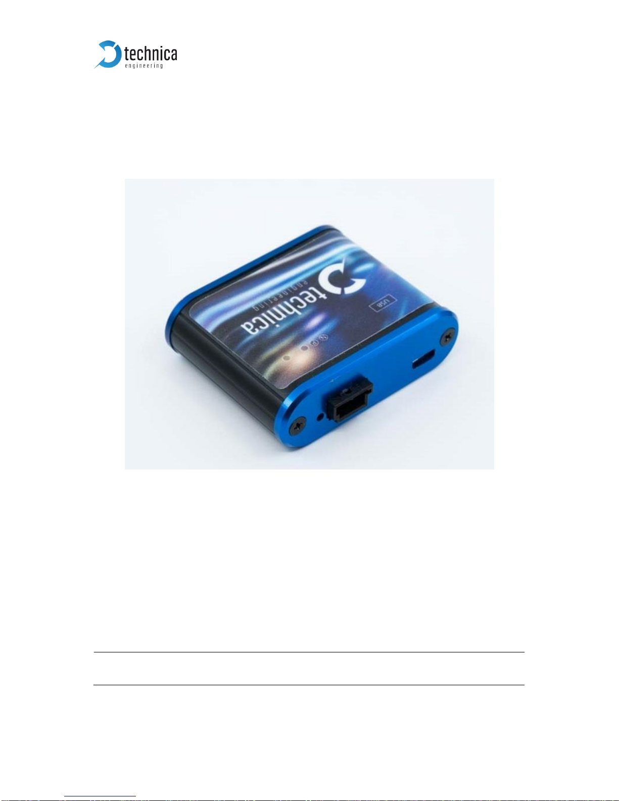
Figure 1—1: USB-100BASE-T1 Converter................................................................. 3
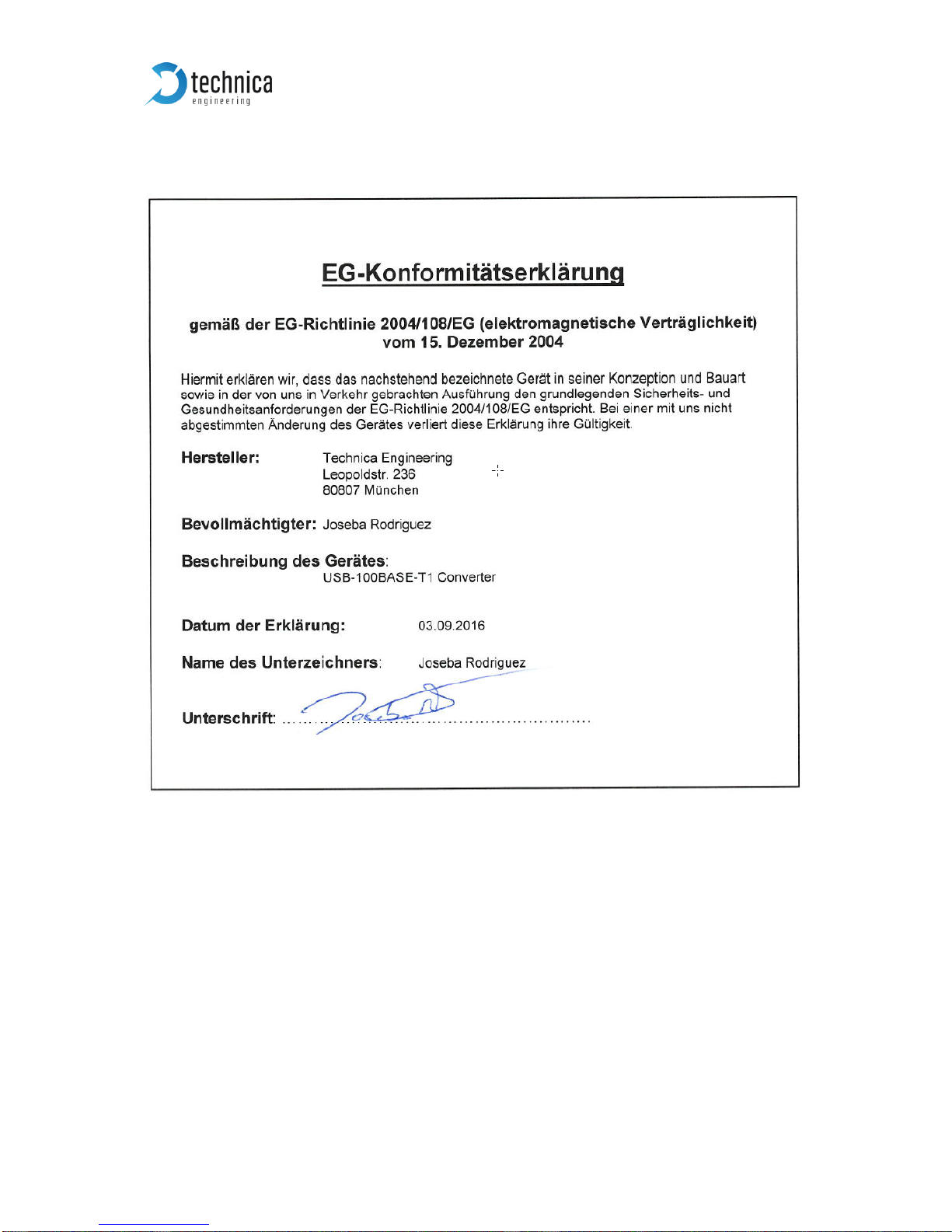
Figure 1—2: Declaration of conformity....................................................................... 5
Figure 2—1: Label of USB-100BASE-T1 Converter with pinning information ............ 6
Figure 3—1: Driver Installation Data Folder................................................................ 8
Figure 3—2: Installation as Administrator................................................................... 8
Figure 3—3: Start installing the driver ........................................................................ 9
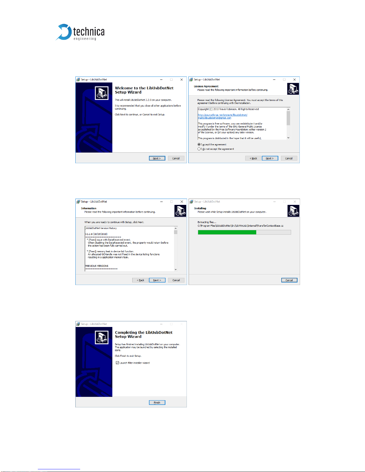
Figure 3—4: Start Installing LibUsbDotNet Library..................................................... 9
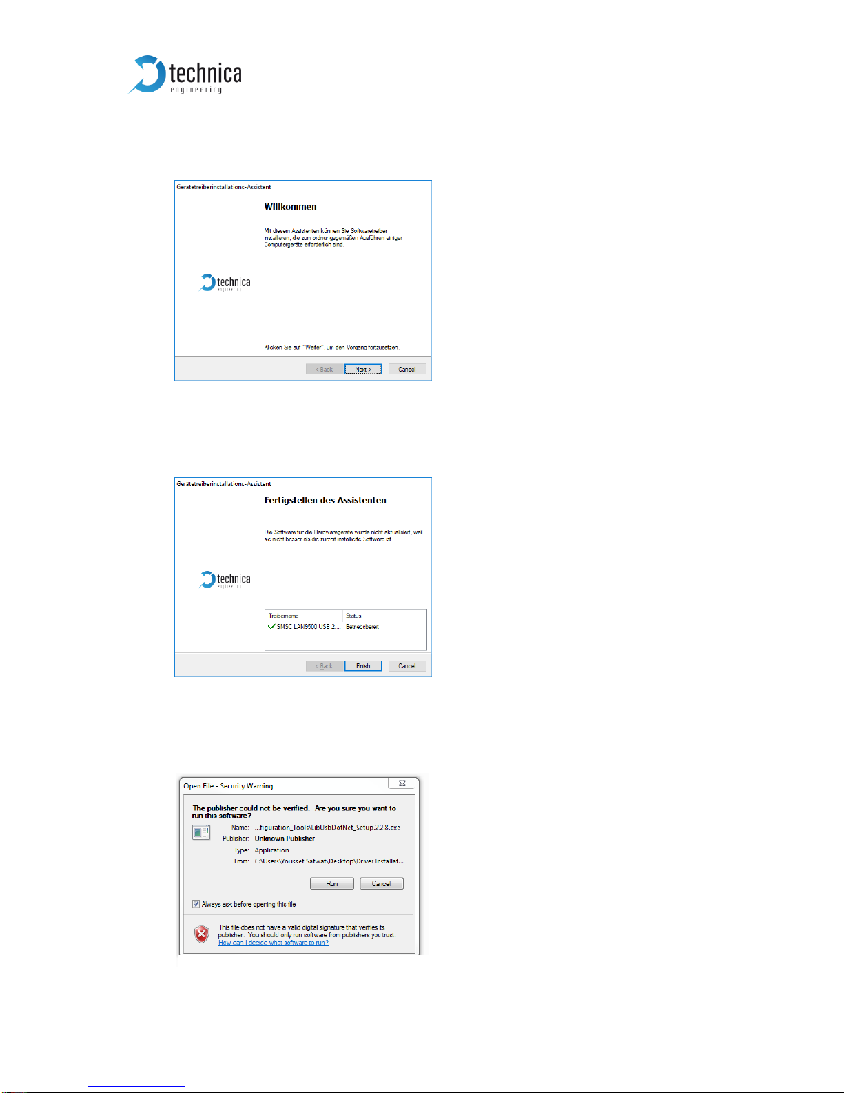
Figure 3—5: Security Warning from Windows............................................................ 9
Figure 3—6: LibUsbDotNet Setup Wizard and License Agreement ....................... 100
Figure 3—7: Installation Information......................................................................... 10
Figure 3—8: Finish of Installation............................................................................. 10
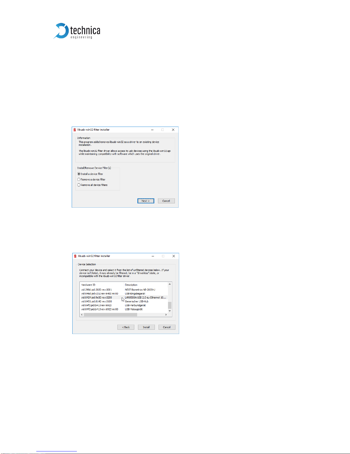
Figure 3—9: Installation of Device Filter................................................................... 11
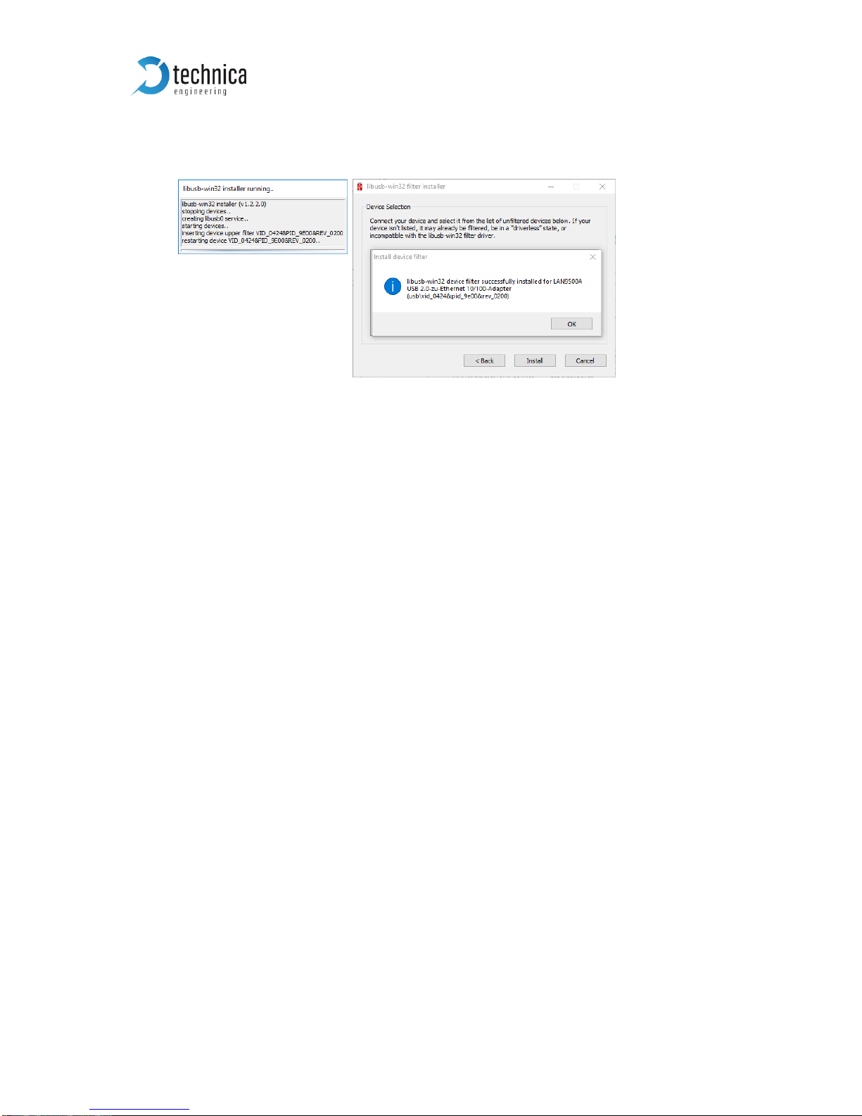
Figure 3—10: Selection of USB-100BASE-T1 Converter Device............................. 11
Figure 3—11: Exit of Wizard................................................................................... 122
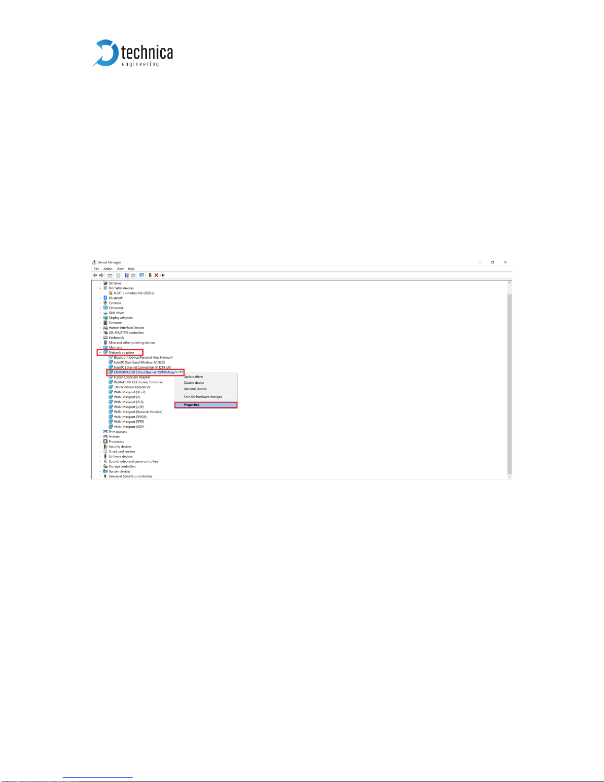
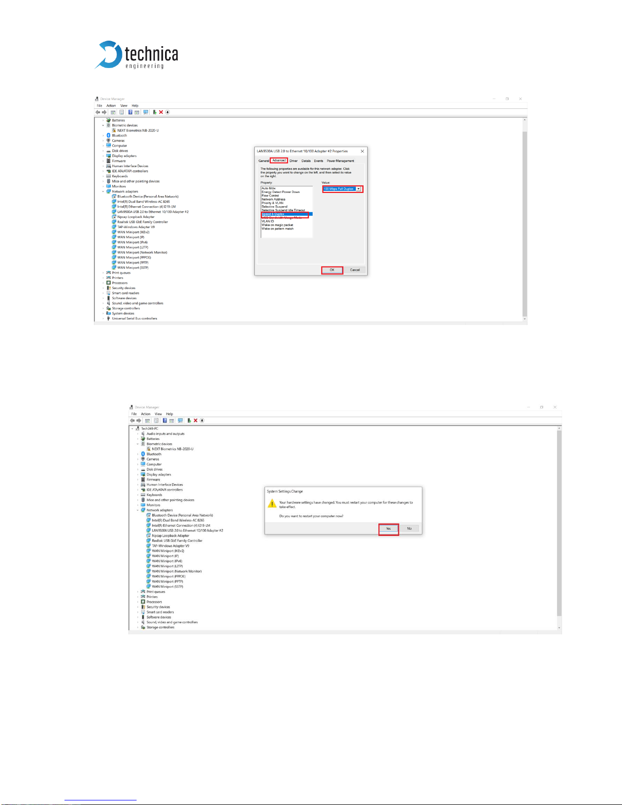
Figure 3—12: NIC properties set up......................................................................... 15
Figure 3—13: NIC set up 100Mbps…………………………..…….…………………..…14
Figure 3—14: Apply Changes…………………………………..…………………………14
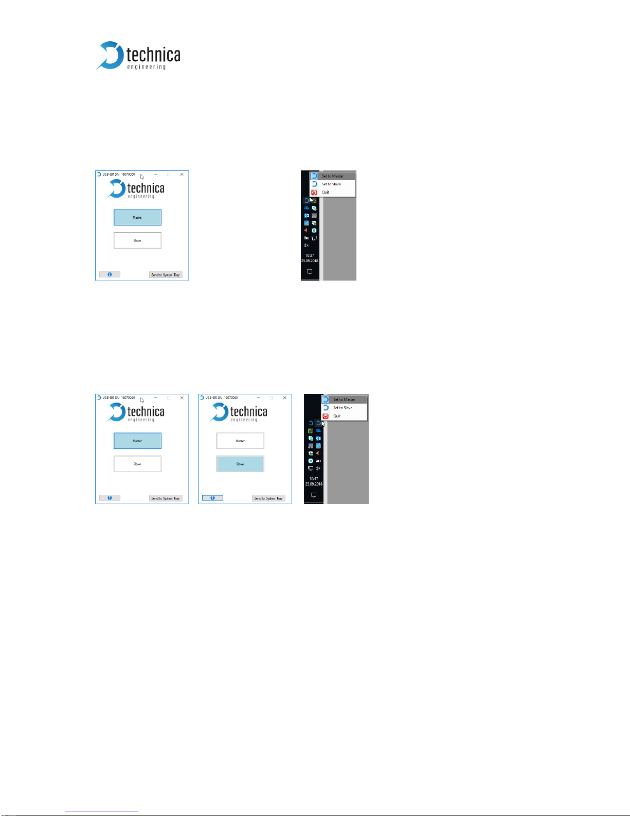
Figure 3—15: System Tray Icon and Configuration
Window………………….……….155
Figure 3—16: Installation of Device
Fitter……………………………………….……….155
Figure 4—1: Configurator or System Tray Application ........................................... 156
Figure 4—1: Two Devices (one Master, One Slave) and two Tray Icons ............... 156